RI7LE910C1SNXModule
Telit Communications S.p.A.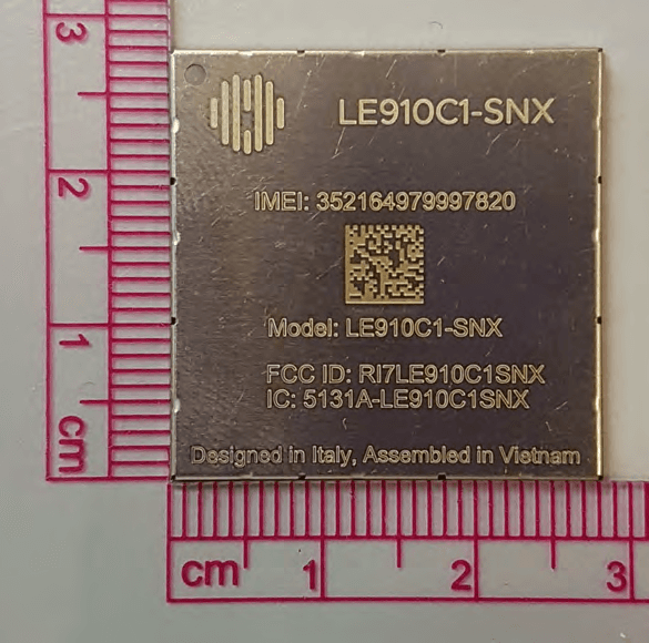
Click to zoom
Application Details
- Equipment Class
- PCB - PCS Licensed Transmitter
- Date of Grant
- May 03, 2023
- Application Purpose
- Original Equipment
- Date of Application
- May 01, 2023
- Equipment Note
- Module
- Frequency Range
- 1850.00000000 - 1910.00000000
- Company
- Telit Communications S.p.A.
- Country
- Italy
Documents & Files
Document Text
Text extracted from the exhibit documents filed with the FCC. Open a document above to read the original.
Users Manual
LE910Cx Hardware Design Guide 1VV0301298 Rev. 40 – 2023-04-27 Telit Technical Documentation LE910Cx Hardware Design Guide 1VV0301298 Rev.37 Page 2 of 148 2023-03-16 Not Subject to NDA APPLICABILITY TABLE This documentation applies to the following products: PRODUCTS DESCRIPTION LE910C1-NA North America – AT&T with global roaming LE910C1-NAD North America – AT&T with global roaming and Data only LE910C1-NS North America - Sprint variant LE910C1-AP APAC variant CAT1 variant LE910C4-AP APAC variant CAT4 variant LE910C1-APX APAC variant CAT1 variant LE910C4-EU Europe CAT4 variant LE910C1-EU Europe CAT1 variant LE910C1-EUX Europe CAT1 variant LE910C4-NF North America CAT4 variant LE910C4-NFD North America CAT4 variant and Data only LE910C1-NF North America CAT1 variant LE910C1-NFD North America CAT1 variant and Data only LE910C1-SA North America CAT1 variant – AT&T LE910C1-SAD North America CAT1 variant – AT&T and Data only LE910C1-SAX North America CAT1 variant – AT&T LE910C1-SAXD North America CAT1 variant – AT&T and Data only LE910C1-ST North America CAT1 variant – T Mobile LE910C1-SV North America CAT1 variant – Verizon LE910C1-SVX North America CAT1 variant – Verizon LE910C1-LA Latin America CAT1 variant LE910C4-LA Latin America CAT4 variant LE910C4-CN China CAT4 variant LE910C1-WWX Worldwide CAT1 variant LE910C4-WWX Worldwide CAT4 variant LE910C1-WWXD Worldwide CAT1 variant and Data only LE910C4-WWXD Worldwide CAT4 variant and Data only LE910Cx Hardware Design Guide 1VV0301298 Rev.37 Page 3 of 148 2023-03-16 Not Subject to NDA PRODUCTS DESCRIPTION LE910C1-SNX North America CAT1 variant LE910C1-SNXD North America CAT1 variant and Data only Table 1: Applicability table Note: ‘X’ means ThreadX OS in LE910C1-EUX, LE910C1-SAX(D), LE910C1-SVX, LE910Cx-WWX(D), LE910C1-APX and LE910C1- SNX(D). The other models which don’t have the letter ‘X’ are Linux OS. Note: Data only variants share the same HW of related voice variants and the voice features are disabled by SW. LE910Cx Hardware Design Guide 1VV0301298 Rev.37 Page 4 of 148 2023-03-16 Not Subject to NDA CONTENTS APPLICABILITY TABLE 2 CONTENTS 4 1. INTRODUCTION 10 Scope 10 Audience 10 Contact Information, Support 10 Symbol Conventions 11 Related Documents 11 2. GENERAL PRODUCT DESCRIPTION 13 Overview 13 Applications 14 General Functionality and Main Features 14 Block Diagram 16 Environmental Requirements 18 2.5.1. Temperature Range 18 2.5.2. RoHS Compliance 18 Operating Frequency Bands 18 2.6.1. RF Bands per Regional Variant 18 2.6.2. Reference Table of RF Bands Characteristics 20 RF Parameters 23 2.7.1. Sensitivity 23 2.7.2. Output power 24 Mechanical Specifications 25 2.8.1. Dimensions 25 2.8.2. Weight 25 3. MODULE CONNECTIONS 26 Pin-out 26 Signals That Must Be Connected 34 LGA Pads Layout 35 Backward Compatibility to xE910 Family 35 4. ELECTRICAL SPECIFICATIONS 37 LE910Cx Hardware Design Guide 1VV0301298 Rev.37 Page 5 of 148 2023-03-16 Not Subject to NDA Absolute Maximum Ratings – Not Operational 37 Recommended Operating Conditions 37 Logic Level Specifications 38 4.3.1. 1.8V Pads - Absolute Maximum Ratings 38 4.3.2. 1.8V Standard GPIOs 38 4.3.3. 1.8V SD Card Pads 39 4.3.4. 1.8V SIM Card Pads 39 4.3.5. Dual Voltage Pads - Absolute Maximum Ratings 40 4.3.6. SD Card Pads @ 2.95V 40 4.3.7. SIM Card Pads @2.95V 40 5. HARDWARE COMMANDS 42 Turning on the LE910Cx Module 42 Initialization and Activation State 42 Turning off the LE910Cx Module 46 5.3.1. Shutdown by Software Command 47 5.3.2. Hardware Shutdown 48 5.3.3. Unconditional Hardware Shutdown 48 Powering OFF the Module 50 Fast Power Down 50 5.5.1. Fast Shut Down by Hardware 50 5.5.2. Fast Shut Down by Software 53 6. POWER SUPPLY 54 Power Supply Requirements 54 Power Consumption 54 General Design Rules 56 6.3.1. Electrical Design Guidelines 57 6.3.1.1. + 5V Input Source Power Supply – Design Guidelines 57 6.3.1.2. + 12V Input Source Power Supply – Design Guidelines 58 6.3.1.3. Battery Source Power Supply – Design Guidelines 59 6.3.2. Thermal Design Guidelines 60 6.3.3. Power Supply PCB Layout Guidelines 61 7. ANTENNA(S) 63 GSM/WCDMA/TD-SCDMA/LTE Antenna Requirements 63 LE910Cx Hardware Design Guide 1VV0301298 Rev.37 Page 6 of 148 2023-03-16 Not Subject to NDA GSM/WCDMA/TD-SCDMA/LTE Antenna – PCB Line Guidelines 64 GSM/WCDMA/LTE Antenna – Installation Guidelines 65 Antenna Diversity Requirements 65 GNSS Antenna Requirements 66 7.5.1. Combined GNSS Antenna 67 7.5.2. Linear and Patch GNSS Antenna 67 7.5.3. Front End Design Considerations 67 7.5.4. GNSS Antenna – PCB Line Guidelines 68 7.5.5. GNSS Antenna – Installation Guidelines 68 8. HARDWARE INTERFACES 69 USB Port 69 HSIC Interface (Optional) 71 SGMII Interface 71 8.3.1. Ethernet Control interface 71 Serial Ports 72 8.4.1. Modem Serial Port 1 Signals 72 8.4.2. Modem Serial Port 2 74 8.4.3. RS232 Level Translation 75 Peripheral Ports 76 8.5.1. SPI – Serial Peripheral Interface 76 8.5.2. I2C - Inter-integrated Circuit 77 8.5.3. SD/MMC Card Interface 78 8.5.4. WiFi SDIO Interface 79 Audio Interface 80 8.6.1. Digital Audio 80 8.6.1.1. Short Frame Timing Diagrams 82 8.6.1.2. Long Frame Timing Diagrams 83 8.6.1.3. I2S Digital Audio Diagram 85 General Purpose I/O 86 8.7.1. Using a GPIO Pad as Input 88 8.7.2. Using a GPIO Pad as an interrupt / Wakeup source 89 8.7.3. Using a GPIO Pad as Output 89 9. MISCELLANEOUS FUNCTIONS 90 Indication of Network Service Availability 90 LE910Cx Hardware Design Guide 1VV0301298 Rev.37 Page 7 of 148 2023-03-16 Not Subject to NDA Indication of Software Ready 91 RTC – Real Time Clock 91 VAUX Power Output 91 ADC Converter 91 9.5.1. Description 91 9.5.2. Using the ADC Converter 92 Using the Temperature Monitor Function 92 GNSS Characteristics 92 10. MOUNTING THE MODULE ON YOUR BOARD 94 General 94 Finishing & Dimensions 94 Recommended Footprint for the Application 100 Stencil 104 PCB Pad Design 104 Recommendations for PCB Pad Dimensions (mm) 104 Solder Paste 105 10.7.1. Solder Reflow 105 10.7.2. Cleaning 106 11. APPLICATIO…
Text truncated - open the document above for the full version.
Attestation Statements
Telit Communications S.p.A. Via Stazione di Prosecco n. 5/B 34010 Sgonico (TS) - ITALY Phone +39 040 4192 111 Fax +39 040 4192 333 Cap. Soc. € 3.000.000 Partita IVA 03711600266 Cod.Fisc. 03711600266 Nr. R.E.A. TS-120027 Società soggetta all'attività di direzione e coordinamento da parte di Telit Communications PLC con sede in Londra (art.2497 bis C.C.) Società con socio unico (Telit Communications PLC) Date: 2023-04-21 To whom it may concern Ref: Agent letter for FCC ID: RI7LE910C1SNX We, Telit Communications S.p.A., Via Stazione di Prosecco, 5/B. 34010 Sgonico, Trieste (Italy), hereby appoint Element Materials Technology Washington DC LLC. to act as our agent in the preparation of this application for equipment certification, including the signing of all documents relating to these matters. We certify that submitted documents properly describe the device or system for which equiment certification is sought. We also certify that each unit manufactured, imprted or marketed, as defined in the FCC or Innovation, Science and Economic Development (ISED) regulations will have affixed to it a label identical to that submitted for approval with this application. For instances where our authorized agent signs the application for certification on our behalf, we acknowledge that all responsibility for complying with the terms and conditions of Certification, as specified by Element Materials Technology Washington DC LLC., still resides with Telit Communications S.p.A, Viale Stazione di Prosecco 5/b, 34010, Trieste, Italy. If you have any questions regarding this, please don’t hesitate to contact us. For TCB applicaitons, We certify that we are not subject to denial of federal benefits, that includes FCC benefits, pursuant to Section 5301 of the Anti-Drug Abuse Act of 1988, 21 U.S.C. 862. Further, no party, as defined in 47 CFR 1.2002 (b), to the application is subject to denial of federal benefits, that includes FCC benefits. Thank you for your attention to this matter. Agency Agreement Expiration Date: 6 months. Sincerely, Paolomaria Schiratti VP Global Certification, R&D Telephone: 0039 040 4192 111 Email: [email protected] DocuSign Envelope ID: FD02BB48-6016-4453-82FB-B72D396654DE
Attestation Statements
Telit Communications S.p.A. Via Stazione di Prosecco n. 5/B 34010 Sgonico (TS) - ITALY Phone +39 040 4192 111 Fax +39 040 4192 333 Cap. Soc. € 3.000.000 Partita IVA 03711600266 Cod.Fisc. 03711600266 Nr. R.E.A. TS-120027 Società soggetta all'attività di direzione e coordinamento da parte di Telit Communications LTD con sede in Londra (art.2497 bis C.C.) Società con socio unico (Telit Communications LTD) Federal Communications Commission Equipment Authorization Division, Application Processing Branch Mills Road 7435 Oakland Columbia MD 21046 USA 2022-02-24 U.S. AGENT FOR SERVICE OF PROCESS - LETTER OF ATTESTATION U.S. Designated Agent: Company Name: Mobilogix Inc. FRN: 0025512666 Contact Name: Ramy Mourad, R&D Director Company Address: 5500 Trabuco Rd Suite 150 - Irvine – CA - United States Telephone No.: +1 949 540 1276 E-mail: [email protected] This letter is to confirm that we designate the above U.S. representative as agent for service of process for Telit Communications S.p.A as noted below, for all the future FCC submissions. Telit Communications S.p.A. and Mobilogix Inc. are companies belonging to the same group Telit IoT Solutions Holding LTD. The applicant accepts and acknowledges the obligation to maintain an agent for no less than one year after the grantee has terminated all marketing and importation or the conclusion of any Commission- related proceeding involving the equipment. The agent is not affiliated with a test lab or TCB. Applicant: Company Name: Telit Communications S.p.A. Grantee Code: RI7 FRN: 0020384608 Company Address: Via Stazione di Prosecco 5/B – 34010 Sgonico (TS) - ITALY Contact Name: Paolomaria Schiratti Telephone No.: +39 0404192222 E-mail: [email protected] Best regards, _____________________ _________________ Paolomaria Schiratti Ramy Mourad VP Global Certification R&D Director DocuSign Envelope ID: B3693FF0-A6A5-407A-BF2C-263F75C7D865
Attestation Statements
Telit Communications S.p.A. Via Stazione di Prosecco n. 5/B 34010 Sgonico (TS) - ITALY Phone +39 040 4192 111 Fax +39 040 4192 333 Cap. Soc. € 3.000.000 Partita IVA 03711600266 Cod.Fisc. 03711600266 Nr. R.E.A. TS-120027 Società soggetta all'attività di direzione e coordinamento da parte di Telit Communications LTD con sede in Londra (art.2497 bis C.C.) Società con socio unico (Telit Communications LTD) Federal Communications Commission Equipment Authorization Division, Application Processing Branch Mills Road 7435 Oakland Columbia MD 21046 USA 2022-04-21 Attestation regarding ‘covered’ equipment and the Covered List for FCCID RI7LE910C1SNX To whom it may concern, Per 2.911(d)(5)(i), Telit Communications S.p.A. certifies that the equipment for which authorization is sought is not “covered” equipment prohibited from receiving an equipment authorization pursuant to section 2.903 of the FCC rules. Per 2.911(d)(5)(ii), Telit Communications S.p.A. certifies that, as of the date of the filing of the appli- cation, the applicant in not identified on the Covered List as an entity producing “covered” equipment. Sincerely, _____________________ Paolomaria Schiratti VP Global Certification [email protected]
Cover Letter(s)
Telit Communications S.p.A. Via Stazione di Prosecco n. 5/B 34010 Sgonico (TS) - ITALY Phone +39 040 4192 111 Fax +39 040 4192 333 Cap. Soc. € 3.000.000 Partita IVA 03711600266 Cod.Fisc. 03711600266 Nr. R.E.A. TS-120027 Società soggetta all'attività di direzione e coordinamento da parte di Telit Communications PLC con sede in Londra (art.2497 bis C.C.) Società con socio unico (Telit Communications PLC) Date: 2023-04-21 To whom it may concern Ref: Modular Approval Letter FCC ID:RI7LE910C1SNX To whom it may concern: The requirements of KDB 996369 has been met and shown on the following statements. Type of Module: Single Modular Tranmsitter No. Requirements Device Conditions Comply (Y/N) 1 The radio elements of the modular transmitter must have their own shielding. The physical crystal and tuning capacitors may be located external to the shielded radio elements. The module has its own RF shielding. Refer to the external photos. Y 2 The modular transmitter must have buffered modulation/data inputs (if such inputs are provided) to ensure that the module will comply with part 15 requirements under conditions of excessive data rates or over-modulation. The EUT has buffered modulation/data inputs. It’s integrated on the chipset. Y 3 The modular transmitter must have its own power supply regulation. Integrated on the chipset Y 4 The modular transmitter must comply with the antenna and transmission system requirements of §15.203, 15.204(b) and 15.204(c). The antenna must either be permanently attached or employ a “unique” antenna coupler. Licensed modular. The maximum antenna gain is show in RF exposure exhibit. Y 5 The modular transmitter must be tested in a stand-alone configuration, i.e., the module must not be inside another device during testing for compliance with part 15 requirements. Tested in a stand-alone configuration Y 6 The modular transmitter must be equipped with either a permanently affixed label or must be capable of electronically displaying its FCC identification number. Refer to external photos. Also the OED manufacturer will be informed to display a label referring to the module. Y 7 The modular transmitter must comply with The user manual instruction Y DocuSign Envelope ID: FD02BB48-6016-4453-82FB-B72D396654DE Telit Communications S.p.A. Via Stazione di Prosecco n. 5/B 34010 Sgonico (TS) - ITALY Phone +39 040 4192 111 Fax +39 040 4192 333 Cap. Soc. € 3.000.000 Partita IVA 03711600266 Cod.Fisc. 03711600266 Nr. R.E.A. TS-120027 Società soggetta all'attività di direzione e coordinamento da parte di Telit Communications PLC con sede in Londra (art.2497 bis C.C.) Società con socio unico (Telit Communications PLC) any specific rules or operating requirements that ordinarily apply to a complete transmitter and the manufacturer must provide adequate instructions along with the module to explain any such requirements. A copy of these instructions must be included in the application for equipment authorization. that the OEM manufacturer how to use/install the module. Refer to the user manual 8 The modular transmitter must comply with any applicable RF exposure requirements in its final configuration. It is designed for mobile or fixed operation. Y If you have any questions regarding this, please don’t hesitate to contact us. Sincerely, Paolomaria Schiratti VP Global Certification, R&D Telephone: 0039 040 4192 111 Email: [email protected] DocuSign Envelope ID: FD02BB48-6016-4453-82FB-B72D396654DE
Cover Letter(s)
Telit Communications S.p.A. Via Stazione di Prosecco n. 5/B 34010 Sgonico (TS) - ITALY Phone +39 040 4192 111 Fax +39 040 4192 333 Cap. Soc. € 3.000.000 Partita IVA 03711600266 Cod.Fisc. 03711600266 Nr. R.E.A. TS-120027 Società soggetta all'attività di direzione e coordinamento da parte di Telit Communications PLC con sede in Londra (art.2497 bis C.C.) Società con socio unico (Telit Communications PLC) Date: 2023-05-02 To whom it may concern Ref: Confidentiality Request for FCC ID: RI7LE910C1SNX Pursuant to FCC 47 CRF 0.457(d) and 0.459 and IC RSP-100, Section 10, We, Telit Communications S.p.A., Via Stazione di Prosecco, 5/B. 34010 Sgonico, Trieste (Italy), request that a part of the subject FCC/IC application be held confidential. Type of Confidentiality Requested Exhibit Short Term Permanent Block Diagrams Short Term External Photos Short Term Internal Photos Short Term Permanent Operation Description/Theory of Operation Short Term Permanent Part List / Tune-Up Procedure Short Term Permanent Schematics Short Term Test Setup Photos Short Term Permanent User’s Manual Telit Communications S.P.A. has spent substantial effort in developing this product and it is one of the first of its kind in industry. Having the subject information easily available to "competition" would negate the advantage they have achieved by developing this product. Not protecting the details of the design will result in financial hardship. Permanent Confidentiality: The applicant requests the exhibits listed above as permanently confidential be permanently withheld from public review due to materials that contain trade secrets and proprietary information not customarily released to the public. Short-Term Confidentiality: The applicant requests the exhibits selected above as short term confidential be withheld from public view for a period of 180 days from the date of the Grant of Equipment Authorization and prior to marketing. This is to avoid premature release of sensitive information prior to marketing or release of th e product to the public. Applicant is also aware that they are responsible to notify Element Materials Technology, in the event information regarding the product or the product is made available to the public. Element Materials Technology. will then release the documents listed above for public disclosure pursuant to FCC Public Notice DA 04-1705. Sincerely, Paolomaria Schiratti VP Global Certification, R&D Telephone: 0039 040 4192 111 Email: [email protected]
External Photos
TECHNICAL MANUAL Telit LE910C1-SNX HW 1.00 Data Terminal Module Pag.6 of 31 Rev.0 2023/04/04 Code: 1vv0301825 ANNEX 2 LE910C1-SNX MODULE PHOTOS TECHNICAL MANUAL Telit LE910C1-SNX HW 1.00 Data Terminal Module Pag.7 of 31 Rev.0 2023/04/04 Code: 1vv0301825 TECHNICAL MANUAL Telit LE910C1-SNX HW 1.00 Data Terminal Module Pag.8 of 31 Rev.0 2023/04/04 Code: 1vv0301825
External Photos
TECHNICAL MANUAL Telit LE910C1-SNXD HW 1.00 Data Terminal Module Pag.6 of 31 Rev.0 2023/04/04 Code: 1vv0301826 ANNEX 2 LE910C1-SNXD MODULE PHOTOS TECHNICAL MANUAL Telit LE910C1-SNXD HW 1.00 Data Terminal Module Pag.7 of 31 Rev.0 2023/04/04 Code: 1vv0301826 TECHNICAL MANUAL Telit LE910C1-SNXD HW 1.00 Data Terminal Module Pag.8 of 31 Rev.0 2023/04/04 Code: 1vv0301826
ID Label/Location Info
TECHNICAL MANUAL Telit LE910C1-SNX HW 1.00 Data Terminal Module Pag.4 of 31 Rev.0 2023/04/04 Code: 1vv0301825 ANNEX 1 LE910C1-SNX MODULE LABEL LAYOUT TECHNICAL MANUAL Telit LE910C1-SNX HW 1.00 Data Terminal Module Pag.5 of 31 Rev.0 2023/04/04 Code: 1vv0301825
ID Label/Location Info
TECHNICAL MANUAL Telit LE910C1-SNXD HW 1.00 Data Terminal Module Pag.4 of 31 Rev.0 2023/04/04 Code: 1vv0301826 ANNEX 1 LE910C1-SNXD MODULE LABEL LAYOUT TECHNICAL MANUAL Telit LE910C1-SNXD HW 1.00 Data Terminal Module Pag.5 of 31 Rev.0 2023/04/04 Code: 1vv0301826
Internal Photos
TECHNICAL MANUAL Telit LE910C1-SNX HW 1.00 Data Terminal Module Pag.6 of 31 Rev.0 2023/04/04 Code: 1vv0301825 ANNEX 2 LE910C1-SNX MODULE PHOTOS TECHNICAL MANUAL Telit LE910C1-SNX HW 1.00 Data Terminal Module Pag.7 of 31 Rev.0 2023/04/04 Code: 1vv0301825 TECHNICAL MANUAL Telit LE910C1-SNX HW 1.00 Data Terminal Module Pag.8 of 31 Rev.0 2023/04/04 Code: 1vv0301825
Internal Photos
TECHNICAL MANUAL Telit LE910C1-SNXD HW 1.00 Data Terminal Module Pag.6 of 31 Rev.0 2023/04/04 Code: 1vv0301826 ANNEX 2 LE910C1-SNXD MODULE PHOTOS TECHNICAL MANUAL Telit LE910C1-SNXD HW 1.00 Data Terminal Module Pag.7 of 31 Rev.0 2023/04/04 Code: 1vv0301826 TECHNICAL MANUAL Telit LE910C1-SNXD HW 1.00 Data Terminal Module Pag.8 of 31 Rev.0 2023/04/04 Code: 1vv0301826
RF Exposure Info
FCC ID: RI7LE910C1SNX IC: 5131A-LE910C1SNX MAXIMUM PERMISSIBLE EXPOSURE REPORT Approved by: Technical Manager Test Report S/N: Test Dates: EUT Type: Page 1 of 7 1M2303070020-04-R1.RI7 03/21/2023 - 03/31/2023 Module V 9.0 02/01/2019 Unless otherwise specified, no part of this report may be reproduced or utilized in any part, form or by any means, electronic or mechanical, including photocopying and microfilm, without written permission from Element. If you have any questions about this or have an inquiry about obtaining additional rights to this report or assembly of contents thereof, please contact [email protected]. Applicant Name: Telit Communications S.p.A. Viale Stazione di Prosecco 5/b Trieste, 34010 Italy Date of Testing: 03/21/2023 - 03/31/2023 Test Report Issue Date: 04/21/2023 Test Site/Location: Element Lab. Columbia, MD, USA Test Report Serial No.: 1M2303070020-04-R1.RI7 FCC ID: RI7LE910 C1SNX IC: 5131A-LE910C1SNX APPLICANT: Telit Communications S.p.A. EUT Type: Module Model/HVIN: LE910C1-SNX Additional Model/HVIN: LE910C1-SNXD FCC Classification: PCS Licensed Transmitter (PCB) FCC Rule Part: FCC Part 1 (§1.1310) and Part 2 (§2.1091) ISED Specification: RSS-102 Issue 5 Test Procedure(s): KDB 447498 D01 This equipment has been shown to be capable of compliance with the applicable technical standards as indicated in the measurement report and was tested in accordance with the measurement procedures specified in FCC KDB 447498 D01. Test results reported herein relate only to the item(s) tested. Note: This revised Test Report (S/N: 1M2303070020-04-R1.RI7) supersedes and replaces the previously issued test report on the same subject device for the same type of testing as indicated. Please discard or destroy the previously issued test report(s) and dispose of it accordingly. I attest to the accuracy of data. All measurements reported herein were performed by me or were made under my supervision and are correct to the best of my knowledge and belief. I assume full responsibility for the completeness of these measurements and vouch for the qualifications of all persons taking them. RJ Ortanez Executive Vice President ELEMENT WASHINGTON DC LLC 7185 Oakland Mills Road, Columbia, MD 21046 USA Tel. 410.290.6652 / Fax 410.290.6654 http://www.element.com RF EXPOSURE EVALUATION Maximum Permissible Exposure (MPE) FCC ID: RI7LE910C1SNX IC: 5131A-LE910C1SNX MAXIMUM PERMISSIBLE EXPOSURE REPORT Approved by: Technical Manager Test Report S/N: Test Dates: EUT Type: Page 2 of 7 1M2303070020-04-R1.RI7 03/21/2023 - 03/31/2023 Module V 9.0 02/01/2019 Unless otherwise specified, no part of this report may be reproduced or utilized in any part, form or by any means, electronic or mechanical, including photocopying and microfilm, without written permission from Element. If you have any questions about this or have an inquiry about obtaining additional rights to this report or assembly of contents thereof, please contact [email protected]. T A B L E O F C O N T E N T S 1.0 RF EXPOSURE EVALUATION – MAXIMUM PERMISSIBLE EXPOSURE (MPE) ........................ 3 1.1 Introduction ............................................................................................................................................ 3 1.2 EUT Description ..................................................................................................................................... 4 1.3 Procedure .............................................................................................................................................. 4 1.4 Summary of Results............................................................................................................................... 6 2.0 CONCLUSION ................................................................................................................................. 7 FCC ID: RI7LE910C1SNX IC: 5131A-LE910C1SNX MAXIMUM PERMISSIBLE EXPOSURE REPORT Approved by: Technical Manager Test Report S/N: Test Dates: EUT Type: Page 3 of 7 1M2303070020-04-R1.RI7 03/21/2023 - 03/31/2023 Module V 9.0 02/01/2019 Unless otherwise specified, no part of this report may be reproduced or utilized in any part, form or by any means, electronic or mechanical, including photocopying and microfilm, without written permission from Element. If you have any questions about this or have an inquiry about obtaining additional rights to this report or assembly of contents thereof, please contact [email protected]. 1.0 R F E X P O S U R E E V A L U A T I O N – M A X I M U M P E R M I S S I B L E E X P O S U R E ( M P E ) 1.1 Introduction This document is prepared to show compliance with the RF Exposure requirements as required in §1.1310 of the FCC Rules and Regulations and RSS-102 of Industry Canada. The limit for Maximum Permissible Exposure (MPE), specified in FCC §1.1310, is listed in Table 1-1. According to FCC §1.1310 and RSS-102: the criteria listed in the following table shall be used to evaluate the environmental impact of human exposure to radio-frequency (RF) radiation as specified in §1.1307(b). Frequency Range (MHz) Electric Field Strength (V/m) Magnetic Field Strength (A/m) Power Density (mW/cm 2 ) Average Time (Minutes) (A) Limits For Occupational / Control Exposures (f = frequency) 30-300 61.4 0.163 1.0 6 300-1500 ... ... f/300 6 1500-100,000 ... ... 5.0 6 (B) Limits For General Population / Uncontrolled Exposure (f = frequency) 30-300 27.5 0.073 0.2 30 300-1500 ... ... f/1500 30 1500-100,000 ... ... 1.0 30 Table 1-1. FCC limits for Maximum Permissible Exposure (MPE) Frequency Range (MHz) Electric Field Strength (V/m) Magnetic Field Strength (A/m) Power Density (W/cm 2 ) Average Time (Minutes) 0.003-10 83 90 - Instantaneous 0.1-10 - 0.73/ ƒ - 6 1.1-10 87/ ƒ 0.5 - - 6 10-20 27.46 0.0728 2 6 20-48 58.07/ ƒ 0.25 0.1540/ ƒ 0.25 8.944/ ƒ 0.5 6 48-300 22.06 0.05852 1.291 6 300-6000 3.142 ƒ 0.3417 0.008335 ƒ 0.3417 0.02619 ƒ 0.6834 6 6000-15000 61.4 0.163 10 6 15000-150000 61.…
Text truncated - open the document above for the full version.
Test Report
FCC ID: RI7LE910C1SNX IC: 5131A-LE910C1SNX PART 22 / RSS-132 MEASUREMENT REPORT Approved by: Technical Manager Test Report S/N: Test Dates: EUT Type: Page 1 of 40 1M2303070020-01-R1.RI7 03/21/2023 - 03/31/2023 Module V3.0 1/4/2022 Unless otherwise specified, no part of this report may be reproduced or utilized in any part, form or by any means, electronic or mechanical, including photocopying and microfilm, without permission in writing from Element. If you have any questions about this or have an inquiry about obtaining additional rights to this report or assembly of contents thereof, please contact [email protected]. Applicant Name: Telit Communications S.p.A. Viale Stazione di Prosecco 5/b Trieste, 34010 Italy Date of Testing: 03/21/2023 - 03/31/2023 Test Report Issue Date: 04/21/2023 Test Site/Location: Element Lab. Columbia, MD, USA Test Report Serial No.: 1M2303070020-01-R1.RI7 FCC ID: IC: Applicant Name: RI7LE910C1SNX 5131A-LE910C1SNX Telit Communications S.p.A. Application Type: Certification Model/HVIN: Additional Model/HVIN: LE910C1-SNX LE910C1-SNXD EUT Type: Module FCC Classification: PCS Licensed Transmitter (PCB) FCC Rule Part: ISED Specification: 22 RSS-132 Issue 4 Test Procedure(s): ANSI C63.26-2015 This equipment has been shown to be capable of compliance with the applicable technical standards as indicated in the measurement report and was tested in accordance with the measurement procedures specified in §2.947. Test results reported herein relate only to the item(s) tested. Note: This revised Test Report (S/N: 1M2303070020-01-R1.RI7) supersedes and replaces the previously issued test report on the same subject device for the same type of testing as indicated. Please discard or destroy the previously issued test report(s) and dispose of it accordingly. I attest to the accuracy of data. All measurements reported herein were performed by me or were made under my supervision and are correct to the best of my knowledge and belief. I assume full responsibility for the completeness of these measurements and vouch for the qualifications of all persons taking them. RJ Ortanez Executive Vice President ELEMENT WASHINGTON DC LLC 7185 Oakland Mills Road, Columbia, MD 21046 USA Tel. 410.290.6652 / Fax 410.290.6654 http://www.element.com PART 22 / RSS-132 MEASUREMENT REPORT FCC ID: RI7LE910C1SNX IC: 5131A-LE910C1SNX PART 22 / RSS-132 MEASUREMENT REPORT Approved by: Technical Manager Test Report S/N: Test Dates: EUT Type: Page 2 of 40 1M2303070020-01-R1.RI7 03/21/2023 - 03/31/2023 Module V3.0 1/4/2022 Unless otherwise specified, no part of this report may be reproduced or utilized in any part, form or by any means, electronic or mechanical, including photocopying and microfilm, without permission in writing from Element. If you have any questions about this or have an inquiry about obtaining additional rights to this report or assembly of contents thereof, please contact [email protected]. T A B L E O F C O N T E N T S 1.0 INTRODUCTION ........................................................................................................................................... 4 1.1 Scope ................................................................................................................................................................. 4 1.2 Element Test Location ........................................................................................................................................ 4 1.3 Test Facility / Accreditations ............................................................................................................................... 4 2.0 PRODUCT INFORMATION ........................................................................................................................... 5 2.1 Equipment Description ....................................................................................................................................... 5 2.2 Device Capabilities ............................................................................................................................................. 5 2.3 Test Configuration .............................................................................................................................................. 5 2.4 Software and Firmware ...................................................................................................................................... 5 2.5 EMI Suppression Device(s)/Modifications .......................................................................................................... 5 3.0 DESCRIPTION OF TESTS ........................................…
Text truncated - open the document above for the full version.
Contact Information
Applicant
Paolomaria Schiratti(VP Global Certification)
Test Firm
Element Materials Technology Washington DC LLCZach Keyser
[email protected]1111111111
Technical Specifications
| # | Rule Parts | Frequency Range | Power Output | Emission | Tolerance |
|---|---|---|---|---|---|
| 1 | 24E | 1.85 GHz - 1.91 GHz | 173.00 mW | 5M83W7D | 2.5 ppm |
Other Applications from Telit Communications S.p.A.
RI7FE910C04WWI
Jul 01, 20265G Radio Module
Equipment Class
PCB - PCS Licensed TransmitterRI7FE910C04NA
Jun 23, 20265G Radio Module
Equipment Class
CBE - Citizens Band End User DevicesRI7LE910T1SN
Apr 09, 2026LE910T1-SN
Equipment Class
JBP - Part 15 Class B Computing Device PeripheralRI7ME310T1W1
Mar 11, 2026ME310T1-W1
Equipment Class
PCB - PCS Licensed TransmitterRI7LE310X1LA
Jan 08, 2026LTE Cat 1 bis module
Equipment Class
JBP - Part 15 Class B Computing Device Peripheral