RI7ROADSTARBluetooth handsfree phone to be installed in cars
Telit Communications S.p.A.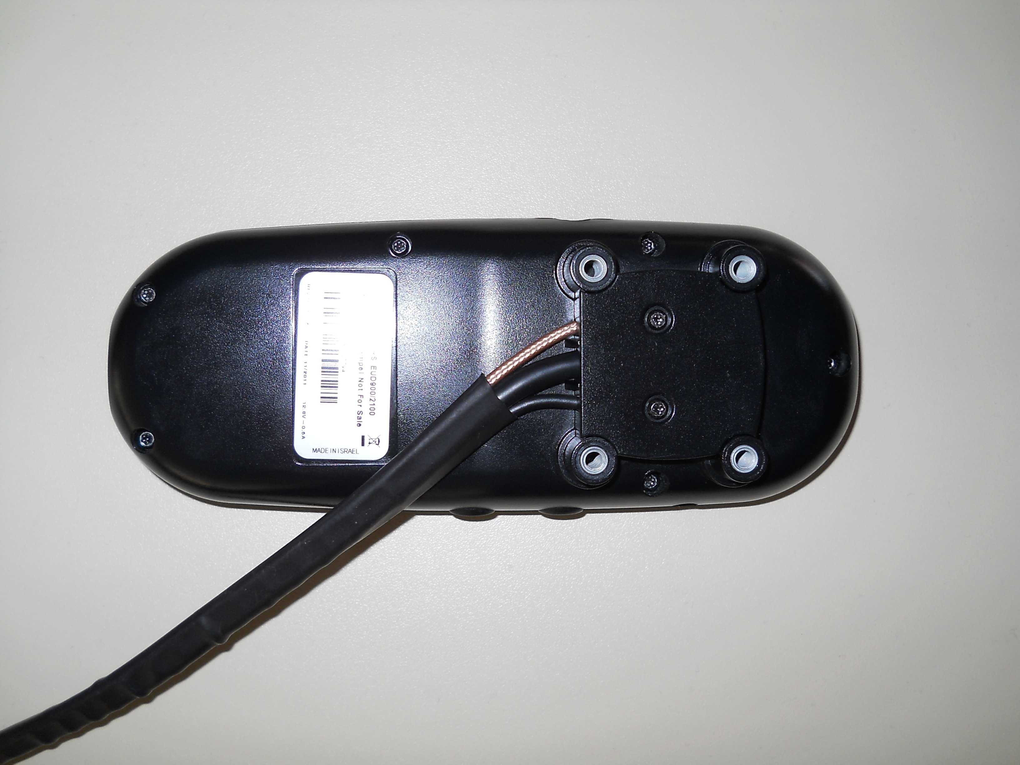
Click to zoom
Application Details
- Equipment Class
- DSS - Part 15 Spread Spectrum Transmitter
- Date of Grant
- Aug 09, 2012
- Application Purpose
- Original Equipment
- Date of Application
- Aug 01, 2012
- Equipment Note
- Bluetooth handsfree phone to be installed in cars
- Frequency Range
- 2402.00000000 - 2480.00000000
- Company
- Telit Communications S.p.A.
- Country
- Italy
Documents & Files
Document Text
Text extracted from the exhibit documents filed with the FCC. Open a document above to read the original.
Users Manual
Mounting instructions Telit RS Car Phone Installation Guide Mounting instructions Table of Content: 1 Carphone kit ............................................................................................................ 3 2 Installation Diagram ................................................................................................. 5 3 Carphone layout ...................................................................................................... 6 4 Preplanned Accessory Positioning ............................................................................ 7 4.1 Plan Phone and Cradle Positions 7 4.2 Plan the Microphone’s Position 8 4.3 Plan the Speaker’s Position 8 5 Installing the Cradle and Phone ................................................................................ 9 5.1 Where to Position (Reminder) 9 5.2 Installing the Cradle and Phone 10 5.3 Installing the Microphone 11 5.4 Installing the Speaker 13 5.5 Installing the Electrical Connections 14 5.6 Installing the Voltage Cable 15 5.7 Installing RF Antenna 16 5.8 Installing GPS Antenna 18 5.9 Installing the SIM card 20 6 Trouble Shooting ................................................................................................... 21 7 Appendix ............................................................................................................... 22 Mounting instructions 1 Carphone kit Mounting instructions Mounting instructions 2 Installation Diagram Mounting instructions 3 Carphone layout Mounting instructions 4 Preplanned Accessory Positioning Positioning of all accessories must be planned in advance before installation begins. • Ensure that no wire braids go through locations where Phone accessories are to be installed. • Ensure that any parts of the handsfree Phone will not interfere with the vehicle or its accessories’ operation. 4.1 Plan Phone and Cradle Positions Note! The best way to determine the Phone’s position to the customer’s full satisfaction is to locate it when the customer is beside you and obtain his/her approval. • Please ensure the Phone’s location does not interfere with the vehicle or its accessories operation: it should not interfere with opening the glove compartment or ashtray, should not prevent access to the lighter, moving the gear stick, operating the hand break etc. Warning! Do not install the Phone in front of the vehicle’s air bag. This restriction must be adhered to, as in the case of an emergency the air bag blows up and can fail to work properly. • Ensure the surface on which this Phone is installed is sufficiently strong to carry the weight and pressure which would be exerted on it. • When selecting the Phone’s location, please ensure the control cable connected to it does not interfere with the vehicle or its accessories’ operation. • Ensure it is safe and convenient to operate the Phone and read the display from the driver’s seat. • Ensure the Phone would be protected from direct sunlight and humidity (air conditioner openings). • Ensure the Phone would be protected from mechanical damage by the car’s accessories. Mounting instructions 4.2 Plan the Microphone’s Position • Install the handsfree Phone’s microphone 30-40 cm away from where the driver speaks when he/she is in their normal driving position. • It is recommended to install the microphone inbetween car roof and windscreen glass and away from external sources of noise. • Install the microphone in a different direction than the speaker so as to avoid echo. 4.3 Plan the Speaker’s Position Note! The speaker and microphone (installed inbetween car roof and windscreen glass above the driver) must face different directions. Note! Do not hide the speaker inside the dash board. If you cover it, sound quality will be lowered. • Locate the speaker at the right side of the main console, at the front of the console, in a location where it would not bother the driver or passengers but would sound best. Mounting instructions 5 Installing the Cradle and Phone 5.1 Where to Position (Reminder) Note! The best way to determine the Phone’s position to the customer’s full satisfaction is to locate it when the customer is beside you and obtain his/her agreement. • Please ensure the Phone’s location does not interfere with the vehicle or its accessories operation: it should not interfere with opening the glove compartment or ashtray, should not prevent access to the lighter, moving the gear stick, operating the hand break etc. Warning! Do not install the Phone in front of the vehicle’s air bag. This restriction must be adhered to, as in the case of an emergency the air bag blows up and can fail to work properly. • Ensure the surface on which this Phone is installed is sufficiently strong to carry the weight and pressure which would be exerted on it. • When selecting the Phone’s location, please ensure the control cable connected to it does not interfere with the vehicle or its accessories’ operation. • Ensure it is safe and convenient to operate the Phone and read the display from the driver’s seat. Mounting instructions • Ensure the Phone would be protected from direct sunlight and humidity (air conditioner openings). • Ensure the Phone would be protected from mechanical damage by the car’s accessories. 5.2 Installing the Cradle and Phone 1. Disassemble the cradle into its two parts. 2. Install one of the cradle parts in the determined location in the car with 4 tin screws. Note! If you are not able to locate the cradle properly, please use a adjustable bracket from the station inventory. 3. Install the second cradle part on the handsfree Phone, using the 4 philips screws provided with this kit. Note! Only use the original screws provided with this kit. 4. Connect the two cradle parts. 5. Direct the control cable coming out of the Phone behind the car panel. Mounting instructions 5.3 Installing the Microphone The microphone is provided with a clip which makes it possible to install it inbetween the c…
Text truncated - open the document above for the full version.
Cover Letter(s)
FCC, Request for non-disclosure Date: 10-Aug-09 RF_501, Issue 5 Page 1 of 1 Company Name: TELIT COMMUNICATIONS S.p.A. Address : Via Stazione di Prosecco 5/B City: 34010 Sgonico, Trieste Country: Italy To: Telefication B.V., Dept. FCC TCB Edisonstraat 12A 6902 PK ZEVENAAR The Netherlands Subject: Request for confidentiality FCC ID: RI7ROADSTAR Reference number: Models: RS 850/1900 / RS 900/2100 Dear FCC TCB, 1. Long-Term Confidentiality Pursuant to 47 CFR Section 0.459(a) & (b), we hereby requests non-disclosure and confidential treatment of the following materials submitted in support of FCC certification application: Bill(s) of Material Block Diagrams Operational Description Schematic Diagrams Tune-up Procedure Above materials contain secrets, proprietary and technical information, which would customarily be guarded from competitors under 47 CFR, section 0.457(d)(2). Disclosure or publication or any portion of this company confidential material to other parties could cause substantial competitive harm and provide unjustified benefits for competitors. 2. Short-Term Confidentiality (STC) Pursuant to Public Notice DA 04-1705 of the Commission’s policy, in order to comply with the marketing regulations in 47 CFR §2.803 and the importation rules in 47 CFR §2.1204, a pplicant hereby requests Short-Term Confidential treatment of the following materials (note 1): Internal Photos User’s Manual Test Set-up Photos External Photos Justification: This is to avoid premature release of sensitive information prior to marketing or release of the product to the public. Applicant is also aware that they are responsible to notify FCC in the event information regarding the product or the product is made available to the public. Planned Release Date STC: Sep. 30, 2012 (notes 2, 3, 4, 5) Date: July 31, 2012 Name and signature of applicant: p.a. Brian Tucker Notes: 1) A document or type of document can only have ONE type of confidentiality! 2) Short-Term confidentiality is in principle for 45 days from date of grant; it can be extended max 3 times (total time 180 days max.)! 3) FCC must be informed when marketing begins earlier. 4) Release takes place automatically thus extension must be requested in time. Telefication does not remind you of this! 5) Request for extension or for release must be received by Telefication at least 7 days before date of actual marketing or before expiration of the STC period
ID Label/Location Info
Label design: Label location:
RF Exposure Info
Telefication BV Edisonstraat 12A Zevenaar 6902 PK The Netherlands RF exposure analysis for the equipment RS 850/1900 and RS 900/2100 (FCC ID: RI7ROADSTAR) The output power of the device is extremely low (4,37 mW conducted, 3.91 mW eirp) and far below the 60/f(GHz) mW (60/2.45 mW = 24.48 mW) threshold. For that reason the equipment is categorically excluded from routine environmental evaluation for RF exposure and it is deemed to comply with FCC limits for exposure to electromagnetic fields. This product integrates the HE863-NAR 2G/3G module (FCC ID: RI7HE863NA, IC: 5131A-HE863NA) or HE863-EUR (FCC ID: RI7HE863EU). The HE863-NAR or HE863-EUR module is granted with a modular approval for mobile applications and it is not co-located with the transmitter RI7ROADSTAR. Integration has been done meeting the following conditions: 1. At least 20cm separation distance between the antenna and any person body is maintained at all times. 2. To comply with FCC/IC regulations limiting both maximum RF output power and human exposure to RF radiation, the maximum antenna gain including cable loss in a mobile only exposure condition does not exceed 4.2 dBi. 3. The HE863-NAR or HE863-EUR module antenna is not co-located with any other antennas, including the antenna of the transmitter RI7ROADSTAR. Product configuration is as follows: Model name: RS 850/1900 FCC ID: RI7ROADSTAR Integrated module: HE863-NAR (FCC ID: RI7HE863NA, IC: 5131A-HE863NA) Model: RS 850/1900 FCC ID: RI7ROADSTAR Telit 2G/3G HSPA module Model: HE863-NAR FCC ID: RI7HE863NA IC: 5131A-HE863NA Embedded Bluetooth antenna Antenna to person distance > 20 cm Antenna to person distance > 20 cm Antenna to antenna distance > 20 External 2G/3G antenna Model name: RS 900/2100 FCC ID: RI7ROADSTAR Integrated module: HE863-EUR (FCC ID: RI7HE863EU) Model: RS 900/2100 FCC ID: RI7ROADSTAR Telit 2G/3G HSPA module Model: HE863-EUR FCC ID: RI7HE863EU Embedded Bluetooth antenna Antenna to person distance > 20 cm Antenna to person distance > 20 cm Antenna to antenna distance > 20 External 2G/3G antenna
Test Report
Report Nº(NIE): 35405RRF.003 Page 1 of 99 2012-07-25 FCC LISTED, REGISTRATION NUMBER: 905266 IC LISTED REGISTRATION NUMBER IC 4621A-1 AT4 wireless, S.A. Parque Tecnológico de Andalucía, c/ Severo Ochoa nº 2 29590 Campanillas/ Málaga/ España Tel. 952 61 91 00 - Fax 952 61 91 13 MÁLAGA, C.I.F. A29 507 456 Registro Mercantil de Málaga,Tomo 1169, Libro 82, Folio 133, Hoja MA3729 TEST REPORT REFERENCE STANDARD: USA FCC Part 15.247, 15.109 CANADA RSS-210, RSS-Gen Radio Frequency Devices. Operation within the bands 902 - 928 MHz, 2400 -2483.5 MHz, and 5725 - 5850 MHz. Licence-Exempt Radio Apparatus (All Frequency Bands): Category I Equipment. General Requirements and Information for the Certification of Radio Apparatus. NIE........................................................ : 35405RRF.003 Approved by (name / position & signature) ............... : A. Llamas / RF Lab. Manager .......................................................... Elaboration date .................................... : 2012-07-25 Identification of item tested................ : CAR KIT CELLULAR/GPS/BLUETOOTH Brand name ........................................... : Telit Roadstar Model and/or type reference ................. : RoadStar 850/1900 RoadStar 900/2100 Serial number ........................................ : IMEI: 354508040017778, 354508040017497 Other identification of the product ........ : Commercial name: TELIT ROADSTAR HW version: Rev2 SW version: U2.J.02.01 FCC ID: RI7ROADSTAR IC: 5131A-ROADSTAR Features ................................................. : Car Kit Cellular/Gps/Bluetooth. Bluetooth 2.1+EDR, 12 Vdc power supplied. Description ............................................ : Car Kit Cellular/Gps/Bluetooth Applicant ............................................. : TELIT COMMUNICATION S.P.A. Address .................................................. : Via Stazione di Prosecco 5/B 34010 Sgonico, Trieste - Italy CIF/NIF/Passport...................................: 03711600266 Contact person: Gianmarco Melosu Telephone / Fax ..................................... : +39.070.46.03.246 / +39.070.46.03.250 e-mail: ................................................... : [email protected] Test samples supplier ......................... : Same as applicant Manufacturer ...................................... : Same as applicant Report Nº(NIE): 35405RRF.003 Page 2 of 99 2012-07-25 Test method requested ........................: See Standard Standard ................................................: USA FCC Part 15.247 10-01-09 Edition: Operation within the bands 902 - 928 MHz, 2400 -2483.5 MHz, and 5725 - 5850 MHz. USA FCC Part 15.109: Receiver radiated emission. CANADA RSS-210 Issue 8 (December 2010). CANADA RSS-Gen Issue 3 (December 2010). FCC part 15.247 and Filing and Measurement Guidelines for Frequency Hopping Spread Spectrum System DA 00-705 Released March 30, 2000. ANSI C63.10-2009: American National Standard for Testing Unlicensed Wireless Devices. Test procedure .......................................: PERF010 Non-standardized test method ...............: N/A Used instrumentation .............................: Conducted Measurements Last Cal. date Cal. due date 1. Spectrum analyser Agilent PSA E4440A 2012/02 2014/02 2. DC power supply R&S NGPE 40/40 2011/11 2014/11 Radiated Measurements Last Cal. date Cal. due date 1. Semianechoic Absorber Lined Chamber IR 11. BS N.A. N.A. 2. Control Chamber IR 12.BC N.A. N.A. 3. Hybrid Bilog antenna Sunol Sciences Corporation JB6 2011/05 2014/05 4. Antenna mast EM 1072 NMT N.A. N.A. 5. Rotating table EM 1084-4. ON N.A. N.A. 6. Double-ridge Guide Horn antenna 1-18 GHz HP 11966E 2011/05 2014/05 7. Double-ridge Guide Horn antenna 18- 40 GHz Agilent 119665J 2011/09 2014/09 8. EMI Test Receiver R&S ESIB26 2011/11 2013/11 9. RF pre-amplifier Miteq JS4-12002600- 30-5A. 2010/07 2012/07 10. Multi Device Controller EMCO 2090 N.A. N.A. 11. Spectrum Analyzer Agilent E4440A 2012/02 2014/02 12. RF pre-amplifier Miteq AFS5- 04001300-15-10P-6. 2010/07 2012/07 13. RF pre-amplifier Schaffner CPA 9231A. 2011/06 2013/06 Report template No. .............................: FDT08_13 IMPORTANT: No parts of this report may be reproduced or quoted out of context, in any form or by any means, except in full, without the previous written permission of AT4 wireless, S.A. Report Nº(NIE): 35405RRF.003 Page 3 of 99 2012-07-25 INDEX Competences and guarantees ................................................................................................................ 4 General conditions ................................................................................................................................ 4 Uncertainty............................................................................................................................................ 4 Usage of samples................................................................................................................................... 5 Testing period ....................................................................................................................................... 5 Environmental conditions ..................................................................................................................... 6 Summary ............................................................................................................................................... 7 Remarks and comments ........................................................................................................................ 7 Testing verdicts ..................................................................................................................................... 7 APPENDIX A: Test result .................................................................................................................... 8 Report Nº(NIE): 35405RRF.003 Page 4 of 99 2012-07-25 Competences and guarantees AT4 wireless is a labora…
Text truncated - open the document above for the full version.
Test Setup Photos
Report Nº(NIE): 35405RRF.003 Page 1 of 7 2012-07-25 APPENDIX B: Photographs Report Nº(NIE): 35405RRF.003 Page 2 of 7 2012-07-25 EQUIPMENT FOR RADIATED MEASUREMENTS Report Nº(NIE): 35405RRF.003 Page 3 of 7 2012-07-25 EQUIPMENT FOR CONDUCTED MEASUREMENTS Report Nº(NIE): 35405RRF.003 Page 4 of 7 2012-07-25 GENERAL SET-UP FOR RADIATED MEASUREMENTS Report Nº(NIE): 35405RRF.003 Page 5 of 7 2012-07-25 TEST SET-UP FOR RADIATED MEASUREMENTS BELOW 1 GHz Report Nº(NIE): 35405RRF.003 Page 6 of 7 2012-07-25 TEST SET-UP FOR RADIATED MEASUREMENTES ABOVE 1GHz Report Nº(NIE): 35405RRF.003 Page 7 of 7 2012-07-25 TEST SET-UP FOR CONDUCTED MEASUREMENTES
Contact Information
Applicant
Paolomaria Schiratti(VP Global Certification)
Technical Contact
Test Firm
DEKRA Testing and Certification, S.A.U.Rafael Lopez Martin
Technical Specifications
| # | Rule Parts | Frequency Range | Power Output |
|---|---|---|---|
| 1 | 15C | 2.40 GHz - 2.48 GHz | 4.00 mW |
Other Applications from Telit Communications S.p.A.
RI7FE910C04WWI
Jul 01, 20265G Radio Module
Equipment Class
PCB - PCS Licensed TransmitterRI7FE910C04NA
Jun 23, 20265G Radio Module
Equipment Class
CBE - Citizens Band End User DevicesRI7LE910T1SN
Apr 09, 2026LE910T1-SN
Equipment Class
JBP - Part 15 Class B Computing Device PeripheralRI7ME310T1W1
Mar 11, 2026ME310T1-W1
Equipment Class
PCB - PCS Licensed TransmitterRI7LE310X1LA
Jan 08, 2026LTE Cat 1 bis module
Equipment Class
JBP - Part 15 Class B Computing Device Peripheral