RJPH6160BAInductive Tag Reader
ASSA ABLOY Identification Technologies GmbH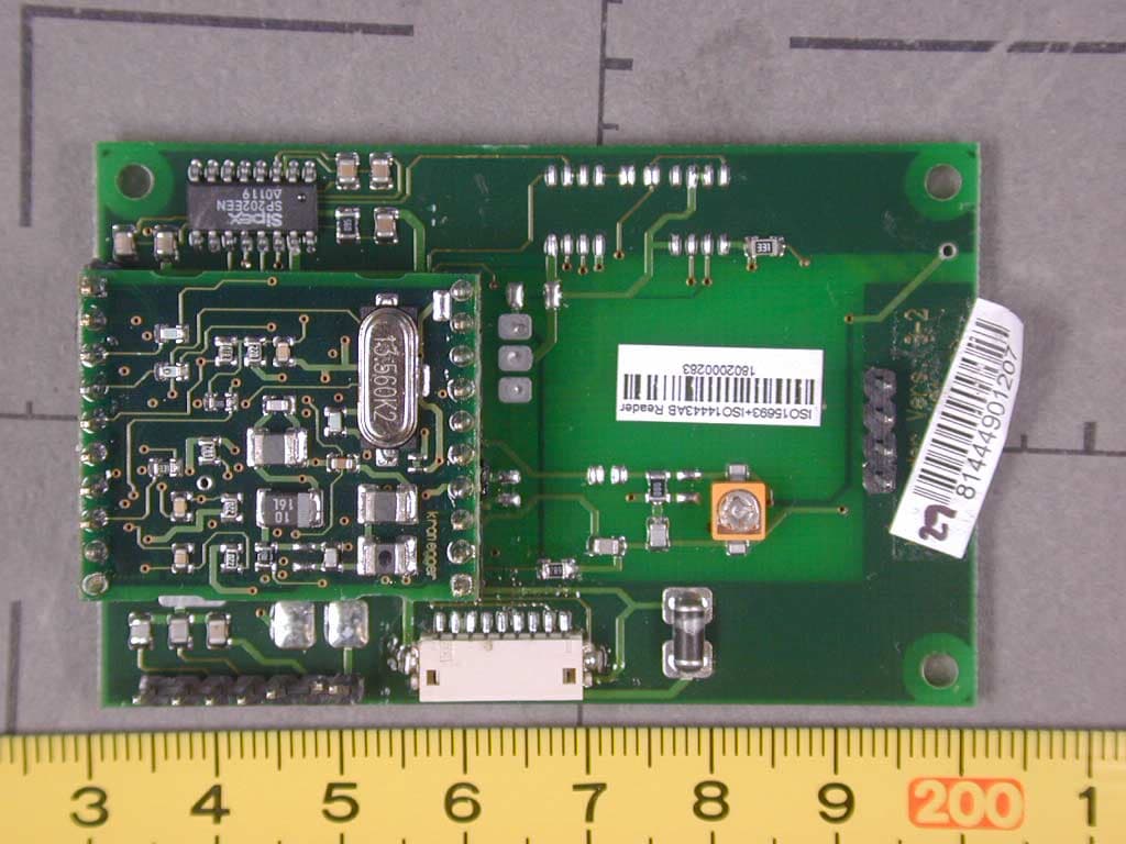
Click to zoom
Application Details
- Equipment Class
- DXX - Part 15 Low Power Communication Device Transmitter
- Date of Grant
- Oct 21, 2003
- Application Purpose
- Original Equipment
- Date of Application
- Oct 21, 2003
- Equipment Note
- Inductive Tag Reader
- Frequency Range
- 13.56000000 - 13.56000000
- Country
- Germany
Documents & Files
Document Text
Text extracted from the exhibit documents filed with the FCC. Open a document above to read the original.
Users Manual
Firmware: 0.2 10/10/2003, wk ACG Identification Technologies GmbH Dantestrasse 4-6 65189 Wiesbaden Germany Fon +49 (611) 1739.0 Fax +49 (611) 1739.198 www.acg.de [email protected] ACG RF PC Handheld Reader Modules H102022. H102024 ACG RF PC Handheld Reader Modules, Version 0.2 ACG Identification Technologies AT Page 1 Table of Content 1 Scope ..................................................................................................2 2 Hardware.............................................................................................3 2.1 Remarks ............................................................................................................ 3 3 Software ..............................................................................................4 3.1 Installation of the PCMCIA driver ...................................................................... 4 3.1.1 HyperTerminal settings ............................................................................... 4 3.2 Pocket PC2002 ................................................................................................. 5 3.3 Pocket PC2003 ................................................................................................. 5 3.4 Writing your own Application in Visual C++ ....................................................... 6 3.4.1 Remarks ..................................................................................................... 7 4 Revision History .................................................................................8 5 References ..........................................................................................8 ACG RF PC Handheld Reader Modules, Version 0.2 ACG Identification Technologies AT Page 2 1 Scope The ACG 13.56 MHz RF PC Handheld Reader Module is a read write device that supports a broad range of transponders. It is designed to communicate with ISO15693, Tagit® and Icode®. With its integrated antenna and compact flash type 2 connector it is ready to use and easily connected into a handheld, laptop or tablet PC. The ACG ISO 14443 AB RF PC Handheld Reader supports Mifare Standard, Ultralight, ProX and DESFire tags. Its open structure of the transfer command set allows to communicate with a broad range of dual processor cards based on ISO 14443-4. Using a PCMCIA adapter it can be connected into a PCMCIA slot type 2. The unit includes a device driver for Windows 98, Me, 2000, NT Service Pack 4 and XP. This document describes the installation of the device driver and an easy access to the RF PC Handheld Reader Modules. The command set of the ACG 13.56 MHz RF PC Handheld Reader Module is described in detail in the document ACG 13.56 MHz Multitag Reader Module [1] and is not listed here. The command set of the ACG ISO 14443 AB RF PC Handheld Reader Module is described in ACG Mifare Family Reader Module documentation [2]. WARNING: Some PCMCIA adapters of handheld PCs are not compatible with the RF PC Handheld Readers. Extensive testing of used hardware is needed prior to any design-ins. No problems have been reported using Compact Flash adapters so far. This product may be bundled with third party software. The warranty provisions of the document do not apply to such third party software. If a separate end user license agreement has been provided for such third party software, use of that software will be governed by that agreement. WARRANTY THIS DEVICE COMPLIES WITH PART 15 OF THE FCC RULES. OPERATION IS SUBJECT TO THE FOLLOWING TWO CONDITIONS: (1) THIS DEVICE MAY NOT CAUSE HARMFUL INTERFERENCE, AND (2) THIS DEVICE MUST ACCEPT ANY INTERFERENCE RECEIVED, INCLUDING INTERFERENCE THAT MAY CAUSE UNDESIRED OPERATION. CAUTION: ANY CHANGES OR MODIFICATIONS NOT EXPRESSLY APPROVED BY THE PARTY RESPONSIBLE FOR COMPLIANCE COULD VOID THE USER’S AUTHORITY TO OPERATE THE EQUIPMENT. ACG RF PC Handheld Reader Modules, Version 0.2 ACG Identification Technologies AT Page 3 2 Hardware 2.1 Remarks The antenna must be free from any metal. A metal will prohibit the antenna field and less reading performance is reached. Reading LED CF Connector Type 2 Antenna Area ACG RF PC Handheld Reader Modules, Version 0.2 ACG Identification Technologies AT Page 4 3 Software The ACG 13.56 MHz RF PC Handheld Reader Module is compatible to the ACG 13.56 MHz Multitag Reader Module H102022 [1]. The ACG ISO 14443 AB RF PC Handheld Reader Module is fully compatible to the ACG ISO 14443 AB Reader Module H102024 [2]. 3.1 Installation of the PCMCIA driver The RF PC Handheld Reader Module can be connected to a laptop or a PC using an adapter of PCMCIA type 2. 1. First time the module is plugged into the slot the user will be prompt to install the correct driver. 2. Follow the instructions on the screen. 3. Click on ‘Have Disk...’ to define the driver location manually. 4. go to folder ‘RCPCHandheldACG’ and double-click on ‘RFPCHandheldACG.inf’. 5. Finish the installation The system has loaded all necessary drivers of the RF PC Handheld Reader Module. Using a terminal program (e.g. HyperTerminal) the module can be accessed by opening the appropriate COM port. 3.1.1 HyperTerminal settings First you have to connect to the correct COM port. Normally the system sets up COM 4 or COM 5 for the PCMCIA slots. The baud rate depends on the startup settings of the reader device. Default is 9600 baud. Description 8 data bits No parity bit 1 stop bit No flow control Figure 3-1: Communication settings ACG RF PC Handheld Reader Modules, Version 0.2 ACG Identification Technologies AT Page 5 3.2 Pocket PC2002 Pocket PC2002 has not included a simple terminal program like HyperTerminal. Following steps create a connection to the RF PC Handheld Reader Module. Pocket PC internally detects all CF or PCMCIA slots and can manage them without any driver installation. 1. Plug the RF PC Handheld Reader Module into the CF slot. 2. Click on ‘start->Settings’ 3. Go to tab ‘connections’ and click on ‘connection with the internet’ 4. Cre…
Text truncated - open the document above for the full version.
Cover Letter(s)
EMV-PrüfzentrumEMI/EMC-Testcenter Coordinates: Äussere Frühlingstrasse 45 ü D-94315 Straubing Telefon (0 94 21) 55 22-0 Telefax (0 94 21) 55 22-99 [email protected] ü http://www.senton.de Senton GmbH ü Äussere Frühlingstrasse 45 ü D-94315 Straubing Phoenix Test-Lab TCB 08 October 2003 In reference to FCC ID RJPH6160BA Justification for Part 15 Unlicensed Modular Transmitter Approval according to DA 00-1407 1. Own RF Shielding Complied, see EUT internal Photographs. No shieldings required 2. Buffered Modulation inputs Complied, see schematic diagrams 3. Own power supply regulation Complied, voltage regulated power supply on board, see schematic diagram 4. Antenna requirements Complied, integrated antenna, pcb track 5. Test in stand-alone configuration Complied, see test report for details. Cable lengths typical to actual use. 6. Own FCC ID Complied, the exterior label will be „Contains FCC ID RJPH6160BA “ 7. Not applicable, the unit operates under Section 15.225 of the FCC Rules 8. RF Exposure requirements Not applicable since the unit operates under section 15.225 of the FCC Rules, the user guide contains general installation and operation instructions. Johann Roidt Senton GmbH
Cover Letter(s)
Request for Confidentiality 06 October 2003 PHOENIX TEST-LAB GmbH Königswinkel 10 D32825 Blomberg Germany RE: Certification Application FCC ID: RJPH6160BA Please be advised that the following information is to be held confidential on behalf of ACG Identification Technologies AT GmbH: • Schematics • Parts Lists • Block Diagram The application contains technical information which ACG Identification Technologies AT GmbH deems to be trade secrets and proprietary. If made public, the information might be used to the disadvantage of the applicant in the market place. Thank you for your attention to this matter. Signatory
External Photos
EMV-Pr ̧fzentrum EMI/EMC-Testcenter FCC ID: RJPH6160BA Photo No. 2 EUT assembled
ID Label/Location Info
Type Label H6160BA ( RM 1356 PP ISO ) : Label size: 20,73 x 12,70 mm ISO MultiTag Reader FCC ID RJPH6160BA σεριεννυμμερ Serial number Firmware: BC ISO 0.9v ISO 15693 + ISO 14443 A+B
Internal Photos
EMV-Pr ̧fzentrum EMI/EMC-Testcenter FCC ID: RJPH6160BA Photo No. 1 EUT disassembled EMV-Pr ̧fzentrum EMI/EMC-Testcenter FCC ID: RJPH6160BA Photo No. 3 Top view of Main PCB EMV-Pr ̧fzentrum EMI/EMC-Testcenter FCC ID: RJPH6160BA Photo No. 4 Bottom view of Main PCB EMV-Pr ̧fzentrum EMI/EMC-Testcenter FCC ID: RJPH6160BA Photo No. 5 Top view of RF PCB EMV-Pr ̧fzentrum EMI/EMC-Testcenter FCC ID: RJPH6160BA Photo No. 6 Bottom view of RF PCB
Operational Description
Firmware: 0.2 10/10/2003, wk ACG Identification Technologies GmbH Dantestrasse 4-6 65189 Wiesbaden Germany Fon +49 (611) 1739.0 Fax +49 (611) 1739.198 www.acg.de [email protected] ACG RF PC Handheld Reader Modules H102022. H102024 ACG RF PC Handheld Reader Modules, Version 0.2 ACG Identification Technologies AT Page 1 Table of Content 1 Scope ..................................................................................................2 2 Hardware.............................................................................................3 2.1 Remarks ............................................................................................................ 3 3 Software ..............................................................................................4 3.1 Installation of the PCMCIA driver ...................................................................... 4 3.1.1 HyperTerminal settings ............................................................................... 4 3.2 Pocket PC2002 ................................................................................................. 5 3.3 Pocket PC2003 ................................................................................................. 5 3.4 Writing your own Application in Visual C++ ....................................................... 6 3.4.1 Remarks ..................................................................................................... 7 4 Revision History .................................................................................8 5 References ..........................................................................................8 ACG RF PC Handheld Reader Modules, Version 0.2 ACG Identification Technologies AT Page 2 1 Scope The ACG 13.56 MHz RF PC Handheld Reader Module is a read write device that supports a broad range of transponders. It is designed to communicate with ISO15693, Tagit® and Icode®. With its integrated antenna and compact flash type 2 connector it is ready to use and easily connected into a handheld, laptop or tablet PC. The ACG ISO 14443 AB RF PC Handheld Reader supports Mifare Standard, Ultralight, ProX and DESFire tags. Its open structure of the transfer command set allows to communicate with a broad range of dual processor cards based on ISO 14443-4. Using a PCMCIA adapter it can be connected into a PCMCIA slot type 2. The unit includes a device driver for Windows 98, Me, 2000, NT Service Pack 4 and XP. This document describes the installation of the device driver and an easy access to the RF PC Handheld Reader Modules. The command set of the ACG 13.56 MHz RF PC Handheld Reader Module is described in detail in the document ACG 13.56 MHz Multitag Reader Module [1] and is not listed here. The command set of the ACG ISO 14443 AB RF PC Handheld Reader Module is described in ACG Mifare Family Reader Module documentation [2]. WARNING: Some PCMCIA adapters of handheld PCs are not compatible with the RF PC Handheld Readers. Extensive testing of used hardware is needed prior to any design-ins. No problems have been reported using Compact Flash adapters so far. This product may be bundled with third party software. The warranty provisions of the document do not apply to such third party software. If a separate end user license agreement has been provided for such third party software, use of that software will be governed by that agreement. WARRANTY THIS DEVICE COMPLIES WITH PART 15 OF THE FCC RULES. OPERATION IS SUBJECT TO THE FOLLOWING TWO CONDITIONS: (1) THIS DEVICE MAY NOT CAUSE HARMFUL INTERFERENCE, AND (2) THIS DEVICE MUST ACCEPT ANY INTERFERENCE RECEIVED, INCLUDING INTERFERENCE THAT MAY CAUSE UNDESIRED OPERATION. CAUTION: ANY CHANGES OR MODIFICATIONS NOT EXPRESSLY APPROVED BY THE PARTY RESPONSIBLE FOR COMPLIANCE COULD VOID THE USER’S AUTHORITY TO OPERATE THE EQUIPMENT. ACG RF PC Handheld Reader Modules, Version 0.2 ACG Identification Technologies AT Page 3 2 Hardware 2.1 Remarks The antenna must be free from any metal. A metal will prohibit the antenna field and less reading performance is reached. Reading LED CF Connector Type 2 Antenna Area ACG RF PC Handheld Reader Modules, Version 0.2 ACG Identification Technologies AT Page 4 3 Software The ACG 13.56 MHz RF PC Handheld Reader Module is compatible to the ACG 13.56 MHz Multitag Reader Module H102022 [1]. The ACG ISO 14443 AB RF PC Handheld Reader Module is fully compatible to the ACG ISO 14443 AB Reader Module H102024 [2]. 3.1 Installation of the PCMCIA driver The RF PC Handheld Reader Module can be connected to a laptop or a PC using an adapter of PCMCIA type 2. 1. First time the module is plugged into the slot the user will be prompt to install the correct driver. 2. Follow the instructions on the screen. 3. Click on ‘Have Disk...’ to define the driver location manually. 4. go to folder ‘RCPCHandheldACG’ and double-click on ‘RFPCHandheldACG.inf’. 5. Finish the installation The system has loaded all necessary drivers of the RF PC Handheld Reader Module. Using a terminal program (e.g. HyperTerminal) the module can be accessed by opening the appropriate COM port. 3.1.1 HyperTerminal settings First you have to connect to the correct COM port. Normally the system sets up COM 4 or COM 5 for the PCMCIA slots. The baud rate depends on the startup settings of the reader device. Default is 9600 baud. Description 8 data bits No parity bit 1 stop bit No flow control Figure 3-1: Communication settings ACG RF PC Handheld Reader Modules, Version 0.2 ACG Identification Technologies AT Page 5 3.2 Pocket PC2002 Pocket PC2002 has not included a simple terminal program like HyperTerminal. Following steps create a connection to the RF PC Handheld Reader Module. Pocket PC internally detects all CF or PCMCIA slots and can manage them without any driver installation. 1. Plug the RF PC Handheld Reader Module into the CF slot. 2. Click on ‘start->Settings’ 3. Go to tab ‘connections’ and click on ‘connection with the internet’ 4. Cre…
Text truncated - open the document above for the full version.
Test Report
FCC-ID: Test Report No. 55408-20347-2 Page 1 of 30 Pages Straubing, 15 July 2002 T E S T - R E P O R T No. 55408-20347-2 for RM 1356 PP ISO Inductive Tag Reader Applicant: OMNIKEY AG Purpose of testing: To show compliance with FCC Code of Federal Regulations, CFR 47, Part 15, Subpart C, Section 15.225 Note: The test data of this report relate only to the individual item which has been tested. This report shall not be reproduced except in full extent without the written approval of the testing laboratory. FCC-ID: Test Report No. 55408-20347-2 Page 2 of 29 Pages Table of Contents 1. Administrative Data ............................................................................................. 3 2. Identification of Test Laboratory .......................................................................... 4 3. Summary of Test Results .................................................................................... 5 4. Operation Mode of EUT....................................................................................... 6 5. Configuration of EUT and Peripheral Devices ..................................................... 7 6. Measuring Methods ............................................................................................. 8 6.1. Field strength of in-band emissions (ß15.225 (a)) and unwanted emissions < 30 MHz (ß15.225 (b)) ............................................... 8 6.2. Frequency tolerance (ß15.225 (c))................................................................ 9 6.3. Unwanted Emission 30 MHz - 1 GHz (ß15.225 (b)) .................................... 11 7. Photographs of Test Setups .............................................................................. 13 8. Equipment List................................................................................................... 19 9. Referenced Regulations .................................................................................... 21 10. List of Measurements ........................................................................................ 22 11. Test Results ...................................................................................................... 23 12. Charts taken during testing................................................................................ 29 FCC-ID: Test Report No. 55408-20347-2 Page 3 of 29 Pages 1. Administrative Data Equipment Under Test (EUT): RM 1356 PP ISO Serial number(s): 0001 Type of equipment: Inductive Tag Reader Type of emission: 10K0A1D Parts/accessories: --- FCC-ID: --- Applicant: OMNIKEY AG Kronegger Informationssysteme Parkring 1 8074 Grambach / AUSTRIA Contract identification: Order no. BF02-045 Contact person: Mr. Rohrhofer Manufacturer: OMNIKEY AG Receipt of EUT: 23 May 2002 Dates of test: May to July 2002 Note: --- Responsible for testing: Thomas Eberl Responsible for test report: Thomas Eberl FCC-ID: Test Report No. 55408-20347-2 Page 4 of 29 Pages 2. Identification of Test Laboratory Test Laboratory: Senton GmbH EMI/EMC Test Center (full address): Aeussere Fruehlingstrasse 45 D-94315 Straubing Germany Contact person: Mr. Johann Roidt Communication: Telephone (+49) 0 94 21 / 55 22-0 Fax (+49) 0 94 21 / 55 22-99 eMail: [email protected] FCC registration number: 90926 Industry Canada file number: IC 3050 FCC-ID: Test Report No. 55408-20347-2 Page 5 of 29 Pages 3. Summary of Test Results The tested sample complies with the requirements for set forth in the The Code of Federal Regulations 47, Part 15, Subpart C, Section 15.225 of the Federal Communication Commission (FCC). Johann Roidt Thomas Eberl Technical Manager Test Engineer FCC-ID: Test Report No. 55408-20347-2 Page 6 of 29 Pages 4. Operation Mode of EUT Continuously reading FCC-ID: Test Report No. 55408-20347-2 Page 7 of 29 Pages 5. Configuration of EUT and Peripheral Devices Configuration of cables of EUT Not applicable Configuration of peripheral devices connected to EUT All tests were performed with the EUT connected to a personal computer via RS 232 interface. The EUT was powered by PS/2 interface. FCC-ID: Test Report No. 55408-20347-2 Page 8 of 29 Pages 6. Measuring Methods 6.1. Field strength of in-band emissions (ß15.225 (a)) and unwanted emissions < 30 MHz (ß15.225 (b)) Radiated emissions in the frequency range 9 kHz ñ 30 MHz will be measured initially at a distance of 3 meters. A prescan at 3 meter distance will be performed in a shielded room with the detector of the spectrum analyzer or EMI Receiver set to peak. Final measurement is then performed at 30 meter distance. In case the regulation requires testing at other distances, the result will be extrapolated. The extrapolation factor will be determined by making a second measurement at 10 meter distance. The provisions of 15.31 (d) apply. According to section 15.209 (d) final measurementis performed with the detector set to Quasi Peak except for the frequency bands 9 ñ 90 kHz and 110 ñ 490 kHz where average detector is employed. FCC-ID: Test Report No. 55408-20347-2 Page 9 of 29 Pages 6.2. Frequency tolerance (ß15.225 (c)) 6.2.1. Frequency stability vs. temperature The frequency stability vs. temperature was measured with a spectrum analyzer connected to the output of the transmitter power amplifier via probe antenna while EUT was operating in transmit mode using the assigned frequency. The trace mode of the spectrum analyzer was set to write with frequency count mode activated: RBW = 100 Hz, VBW = 100 Hz, span = 20 kHz, sweep = 1.5 s (auto mode) See figure 1 for the measurement setup. Test equipment used (see equipment list for details): 02, 18, 51, 54, 69, 70, 71 6 9 4 7 5 8 1 2 3 Figure 1: Measurement setup for testing within temperature test chamber 1 Transmitter (EUT) 6 Test cable 2 Probe antenna 7 DC-block 3 Wooden support 8 Attenuator 4 Temperature test chamber 9 Spectrum analyzer 5 DC power supply FCC-ID: Test Report No. 55408-20347-2 Page 10 of 29 Pages 6.2.2. Frequency stability vs. supply voltage The frequency…
Text truncated - open the document above for the full version.
Test Setup Photos
FCC-ID: Test Report No. 55408-20347-2 Page 14 of 29 Pages Radiated Emissions 9 kHz ñ 30 MHz FCC-ID: Test Report No. 55408-20347-2 Page 15 of 29 Pages Radiated Emissions 30 ñ 1000 MHz (anechoic chamber) FCC-ID: Test Report No. 55408-20347-2 Page 16 of 29 Pages Radiated Emissions 30 ñ 1000 MHz (anechoic chamber) continued FCC-ID: Test Report No. 55408-20347-2 Page 17 of 29 Pages Radiated Emissions 30 ñ 1000 MHz (open area test site) FCC-ID: Test Report No. 55408-20347-2 Page 18 of 29 Pages Radiated Emissions 30 ñ 1000 MHz (open area test site) continued
Contact Information
Applicant
Stefan Trautner(Product Manager)
Technical Contact
Senton GmbHJohann Roidt
[email protected]+49-9421-55 22 13
Aeussere Fruehlingstrasse 45 · Straubing · Germany
Non-Technical Contact
Senton GmbHJohann Roidt
[email protected]+49-9421-55 22 13
Test Firm
TUV SUD Product Service GmbH PS-EMC-STRRainer Heller
Technical Specifications
| # | Rule Parts | Frequency Range | Power Output | Tolerance |
|---|---|---|---|---|
| 1 | 15C | 13.56 MHz - 13.56 MHz | - | 0.0050000000 |
Other Applications from ASSA ABLOY Identification Technologies GmbH

RJPRDHC-0202N0-0X
Sep 06, 2006Inductive Tag Reader Module
Equipment Class
DXT - Part 15 Low Power Transceiver, Rx Verified
RJPRDHC-0502N0-0X
Sep 06, 2006Inductive Tad Reader Module
Equipment Class
DXT - Part 15 Low Power Transceiver, Rx Verified