RJY-IP6HD WiFi Camera
Chuango Security Technology Corporation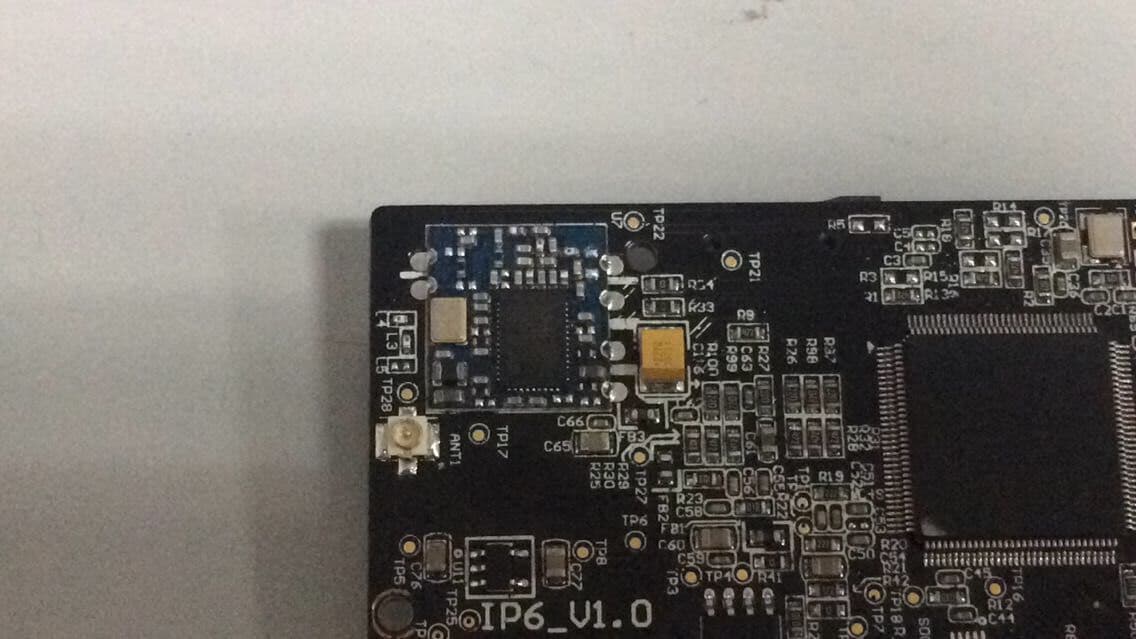
Click to zoom
Application Details
- Equipment Class
- DTS - Digital Transmission System
- Date of Grant
- Apr 28, 2015
- Application Purpose
- Original Equipment
- Date of Application
- Apr 27, 2015
- Equipment Note
- HD WiFi Camera
- Frequency Range
- 2412.00000000 - 2462.00000000
- Country
- China
Documents & Files
Document Text
Text extracted from the exhibit documents filed with the FCC. Open a document above to read the original.
Users Manual
Printed in China PA: IP6-UM-EN/FR/ES/PT-V1.0 © 2015 SMANOS HOLDING LTD. All Rights Reserved. HD WiFi Camera MULTILINGUAL QUICK GUIDE ENESPTFR IP6 ENEN Overview • Front View LED Indicators Camera Microphone Bracket Red indicatorBlinkingEnter WiFi pairing state Blue indicator BlinkingSearching network On Network connected • Side View • Back View Reset button microSD Card Slot Heat Vent Power Jack microSD Card (Not included) Support 32GB microSD card maximum; please do not insert the card after the camera is powered on. This camera automatically records and saves video once every 20 minutes; the video recorded at the earliest will be replaced with the latest ones if the microSD card is full. Note: Please format your microSD card before inserting into this slot if any file had been written in. Check What You Have WiFi Camera×1AC Adapter×1 Quick guide×1Reset Pin×1 ENEN Download the App Download the App by searching “IP6 camera” from Apple Store or Google Play. If you also bought a smanos alarm system, you don't need to download the separate app for the camera, just setup through the app for the alarm system. IP6 Camera WiFi Pairing 1. Preparation • Hold the reset button by using the supplied reset pin until the camera beeps once, and then the red indicator starts to blink • Find and choose the WiFi named “smanos IP6” from your phone’s WiFi list 2. Pairing Camera with WiFi through App ** * • Launch the App, and then tap [+] to add a new camera * Make sure the UID No. is displayed before tapping [OK] • Name your camera, enter the password (default: 888888) and input your home WiFi name & password • When the blue indicator is on, it means the camera has connected with WiFi The paired camera will be displayed in the video list. Note: For safety, it is recommended to change the password of your camera on the setting menu after pairing. ENEN Settings Setting Button Camera Sharing QR Code Device ID Share or Stop Sharing Camera with Your Friends Tap and save the QR code icon on your camera’s [Settings] interface, send to your friends so they can watch your camera from his/her App by scanning the given QR code. If you want to stop sharing the camera, please change the password of camera. Password All the successfully paired phones have the same authority as administrator who can view and set the camera (including changing the password), so it is recommended to pair the phones of users with caution. For non-administrator users, you can share the camera by sending the QR code for them to scan. Sync the Date and Time Check if the camera’s date and time are set correctly. Sync them with your phone’s time if necessary. Enjoy the App Snapshot Record Hold To Talk Speaker ENEN Installation Important: This camera should be placed where the WiFi signal is strong for optimal performance. 1. Separate the mounting template on the bottom of this camera from the bracket by pressing the snap as picture shows 2. Mount the template on the wall by using the supplied screws 3. Push and press the bracket of the camera into the template carefully, and then adjust the angle to achieve best shooting effect Specifications Image sensorSony 1/3” CMOS sensor Min. illuminationColor: 0.01Lux@ (F1.2, AGC ON) Black and white : 0.001Lux@ (F1.2, AGC ON) Shutter time1/50s to 1/100,000s Lens2.4mm F2.0 Angle of view110° Video compressionH.264 Bit rateSelf-adaption Max. image resolution1280 x 720 Frame rate30fps (1280 × 720) StorageBuilt-in microSD card slot, up to 32GB Wireless standardsIEEE802.11b/g/n Frequency range2.4 GHz ~ 2.4835 GHz Channel bandwidth20/40MHz Support Operating conditionsTemperature: -30 °C - 60 °C (-22 °F - 140 °F) Humidity: < 95% (non-condensing) Power supplyDC 5V 1A Power consumption5W MAX Dimensions (L x W x H)80 x 80 x 150 mm ENEN Industry Canada Notice This device complies with Industry Canada licence-exempt RSS standard(s). 1. Operation is subject to the following two conditions: (1) this device may not cause interference, and (2) this device must accept any interference, including interference that may cause undesired operation of the device. 2. Changes or modifications not expressly approved by the party responsible for compliance could void the user's authority to operate the equipment. FCC STATEMENT 1.This device complies with Part 15 of the FCC Rules. Operation is subject to the following two conditions: (1)This device may not cause harmful interference. (2)This device must accept any interference received, including interference that may cause undesired operation. 2. Changes or modifications not expressly approved by the party responsible for compliance could void the user's authority to operate the equipment. NOTE: This equipment has been tested and found to comply with the limits for a Class B digital device, pursuant to Part 15 of the FCC Rules. These limits are designed to provide reasonable protection against harmful interference in a residential installation. This equipment generates uses and can radiate radio frequency energy and, if not installed and used in accordance with the instructions, may cause harmful interference to radio communications. However, there is no guarantee that interference will not occur in a particular installation. If this equipment does cause harmful interference to radio or television reception, which can be determined by turning the equipment off and on, the user is encouraged to try to correct the interference by one or more of the following measures: Reorient or relocate the receiving antenna. Increase the separation between the equipment and receiver. Connect the equipment into an outlet on a circuit different from that to which the receiver is connected. Consult the dealer or an experienced radio/TV technician for help. FCC Radiation Exposure Statement: This equipment complies with FCC radiation exposure limits set forth for an uncontrolled environment. In order to avoid the possibility of exceeding the FCC radio frequency exposure limits, Human proximity to the ante…
Text truncated - open the document above for the full version.
Users Manual
FRFR Avis d’Industrie Canada Le présent appareil est conforme aux CNR d'Industrie Canada applicables aux appareils radio exempts de licence. L'exploitation est autorisée aux deux conditions suivantes : (1) l'appareil ne doit pas produire de brouillage, et (2) l'utilisateur de l'appareil doit accepter tout brouillage radioélectrique subi, même si le brouillage est susceptible d'en compromettre le fonctionnement. Cet appareil numérique ne dépasse pas les Rèlements sur l’interférence radio par un appareil numérique de classe B stipulées dans les Règlement sur l’interférence redio d’industrie Canada. Cámara Wi-Fi en HD IP6 GUÍA RÁPIDA ES Vista general • Vista frontal Indicadores LED Cámara Micrófono Soporte Indicador rojoParpadeandoEntra en estado de vinculación Wi-Fi Indicador azul ParpadeandoBuscando red EncendidoRed conectada • Vista lateral • Vista trasera Botón de reinicio Ranura para tarjeta microSD Ventilación Enchufe de alimentación Tarjeta microSD (no incluida) Compatible con tarjetas microSD de hasta 32 GB; no inserte la tarjeta cuando la cámara esté encendida. Esta cámara graba y guarda vídeos automáticamente cada 20 minutos; los vídeos nuevos sobrescribirán los más antiguos si la tarjeta microSD está llena. Nota: Formatee la tarjeta microSD antes de introducirla en esta ranura si contiene archivos grabados. Compruebe que tenga 1 Cámara Wi-Fi1 Adaptador de corriente 1 Guía rápida1 Pasador para reinicio ESES Descargue la aplicación Descargue la aplicación buscando “IP6 camera” en Apple Store o Google Play. Nota: Si uno utiliza el sistema de panel de Smanos, es necesario descargar nuestro sistema App. IP6 Camera Vinculación Wi-Fi 1. Preparación • Mantenga pulsado el botón de reinicio con el pasador suministrado hasta que la cámara emita un pitido. El indicador rojo empezará a parpadear • Busque y seleccione la red Wi-Fi llamada “smanos IP6” en la lista de redes Wi-Fi de su teléfono 2. Vincular la cámara con la red Wi-Fi a través de la aplicación ** * • Ejecute la aplicación y toque [+] para añadir una cámara nueva * Asegúrese de que aparezca el nº de UID antes de tocar [Aceptar] • Ponga un nombre a la cámara, introduzca la contraseña (predeterminada: 888888) e introduzca el nombre de su red Wi-Fi y la contraseña • Cuando el indicador azul se encienda, indicará que la cámara se ha conectado a la red Wi-Fi La cámara vinculada aparecerá en la lista de vídeos. Nota: Por seguridad, se recomienda cambiar la contraseña de la cámara en el menú de configuración después de la vinculación. ESES Configuración Botón de configuración Código QR para compartir la cámara Identificador del dispositivo Compartir o dejar de compartir la cámara con sus amigos Toque el icono del código QR en la interfaz [Configuración] de su cámara y envíeselo a sus amigos para que puedan ver su cámara desde sus aplicaciones escaneando el código QR. Si desea dejar de compartir la cámara, cambie la contraseña. Contraseña Todos los teléfonos vinculados correctamente tiene autoridad de administrador para ver y configurar la cámara (también pueden cambiar la contraseña), por lo que se recomienda precaución al vincular los teléfonos de usuarios. Puede compartir la cámara con usuarios no administradores enviándoles el código QR para que lo escaneen. Sincronizar la fecha y hora Compruebe si la fecha y hora de la cámara están configuradas correctamente. Sincronícelas con la hora de su teléfono si es necesario. Disfrute de la aplicación Instantánea Grabar Mantener para hablar Altavoz ESES Instalación Importante: Debe colocar la cámara en un lugar donde la señal Wi-Fi sea fuerte para conseguir un rendimiento óptimo. 1. Separe la plantilla de montaje que hay en la parte inferior de la cámara del soporte apretando la lengüeta como se muestra en la imagen 2. Monte la plantilla en la pared usando los tornillos suministrados 3. Apriete cuidadosamente el soporte de la cámara en la plantilla y, a continuación, ajuste el ángulo para conseguir el mejor efecto de grabación Especificaciones Sensor de imagenSensor CMOS Sony 1/3” Iluminación mínimaColor: 0,01 Lux (F1.2, AGC encendido) Blanco y negro: 0,001 Lux (F1.2, AGC encendido) Velocidad de obturación1/50 s a 1/100.000 s Lente2,4 mm F2.0 Ángulo de visión110° Compresión de vídeoH.264 Tasa de bitsAdaptable Resolución máx. de imagen1280 x 720 Fotogramas por segundo30 FPS (1280 × 720) AlmacenamientoRanura de tarjeta microSD integrada, hasta 32 GB Estándar inalámbricoIEEE 802.11b/g/n Rango de frecuencias2,4 GHz-2,4835 GHz Ancho de banda de canalCompatible con 20/40 MHz Condiciones de funcionamientoTemperatura: -30 °C a 60 °C (-22 °F a 140 °F) Humedad: < 95% (sin condensación) Alimentación eléctrica5 V CC 1 A Consumo eléctrico5 W Máx. Medidas (L x A x Al)80 x 80 x 150 mm ESES Câmara Wi-Fi HD IP6 GUIA RÁPIDO PT Descrição • Vista dianteira Indicadores luminosos Câmara Microfone Suporte Indicador luminoso vermelho Intermitente Entrar no estado de emparelhamento sem fios Indicador luminoso azul IntermitenteA procurar rede LigadoRede ligada • Vista lateral • Vista traseira Botão de reinicialização Ranhura p/ cartão microSD Saída de calor Tomada de alimentação Cartão microSD (Não incluído) Suporta no máximo um cartão microSD de 32 GB. Não insira o cartão com a câmara ligada. Esta câmara grava automaticamente e guarda vídeo de 20 em 20 minutos. As imagens de vídeo mais antigas são substituídas por mais recentes quando o cartão microSD fica cheio. Nota: Formate o cartão microSD antes de inseri-lo nesta ranhura, se algum ficheiro tiver sido substituído. Confirme o que tem 1 x Câmara Wi-Fi1 x Transformador CA 1 x Guia rápido1 x Pino de reinicialização PTPT Descarregar a aplicação Descarregue a aplicação procurando por “IP6 camera” na Apple Store ou Google Play. Se você também comprou um sistema de alarme smanos, você não precisa baixar o aplicativo separado para a câmera, apenas configurar através do aplicativo para o sistema de alarme. IP6 Camera Emparelhamento Wi-Fi 1. Preparação • Prima sem soltar o pi…
Text truncated - open the document above for the full version.
Cover Letter(s)
SCS-F18: Project and Product Certification Representative Authorization Letter Page 1 of 2 Rev 5.0 775 Montague Expressway Milpitas, CA 95035 Tel: 408-526-1188 Fax: 408-526-1088 Email: [email protected] Project and Product Certification Representative Authorization Letter Reason for Amendment (current / obsolete) Revision History Approved Date From To Initial Release (obsolete) 1.0 1.0 Nov-14-2006 Revised wording (obsolete) 1.0 2.0 Sept–25-2007 Updated company template (obsolete) 2.0 3.0 Jan-31-2012 Updated letter information (obsolete) 3.0 4.0 May-23-2014 Added FCC ID field (current) 4.0 5.0 Sept 16 2014 SCS-F18: Project and Product Certification Representative Authorization Letter Page 2 of 2 Rev 5.0 Chuango Security Technology Corporation Apr 22, 2015 To: SIEMIC, INC. 775 Montague Expressway, Milpitas, CA 95035 USA Dear Sir/Madam, Re: Product Certification Representative Authorization Letter We, Chuango Security Technology Corporation hereby authorize SIEMIC, Inc. to act as a Certification Body for certifying for the following project(s): Product name: HD WiFi Camera Model No.: IP6 FCC ID: RJY-IP6 Sincerely, Client’s signature Client’s name / title : Ken Li/ CEO Contact address: 6-17, Overseas Students Pioneer Park, No.108, Jiangbin East Road, Economic & Technological Development Zone, Fuzhou 350015, China. Contact telephone: 008659122290811 Email: [email protected]
Cover Letter(s)
SCS-F19: Confidentiality Request Letter Page 1 of 2 Rev 4.0 775 Montague Expressway Milpitas, CA 95035 Tel: 408-526-1188 Fax: 408-526-1088 Email: [email protected] Confidentiality Request Letter Reason for Amendment (current / obsolete) Revision History Approved Date From To Initial Release (obsolete) 1.0 1.0 Nov-14-2006 Adding CFR 2.459 (obsolete) 1.0 2.0 August – 11 - 2008 Updated company template & Added text box (obsolete) 2.0 3.0 Jan-31-2012 Added IC confidentiality letter form (current) 3.0 4.0 March-26-2015 SCS-F19: Confidentiality Request Letter Page 2 of 2 Rev 4.0 Chuango Security Technology Corporation Apr 22, 2015 To: Federal Communications Commission Authorization and Evaluation Division 7435 Oakland Mills Road Columbia, MD Subject: Permanent Confidentiality Request for FCC ID: RJY-IP6 We hereby request confidential treatment of information accompanying this application as outlined below: - Block Diagram - Schematics - Operational Description The above materials contain trade secrets and proprietary information not customarily released to the public. The public disclosure of these materials may be harmful to the applicant and provide unjustified benefits to its competitors. The applicant understands that pursuant to Section 0.457 & 0.459 of the Rules, disclosure of this application and all accompanying documentation will not be made before the date of the Grant for this application. Sincerely, Client’s signature Client’s name / title : Ken Li/ CEO Contact address: 6-17, Overseas Students Pioneer Park, No.108, Jiangbin East Road, Economic & Technological Development Zone, Fuzhou 350015, China. Contact telephone: 008659122290811 Email: [email protected]
External Photos
External Photos
ID Label/Location Info
Label and label location
Internal Photos
Internal Photos Antenna
RF Exposure Info
FCC ID : RJY-IP6 1. RF EXPOSURE 1.1. The Requirement System operating under the provisions of this section shall be operated in a manner that ensures that the public is not exposed to radio frequency energy levels in excess of the Commission’s guidelines. See Section 15.247(b)(4) and Section 1.1307(b)(1) 1.2. Limit For Maximum Permissible Exposure (MPE) Limits for General Population/ Uncontrolled Exposure F = frequency in MHz, * Plane-wave equivalent power density 1.3. MPE Calculation Method Predication of MPE limit at a given distance Equation from page 18 of OET Bulletin 65, Edition 97-01 S=PG/4πR² Where: S=power density P=power input to antenna G=power gain of the antenna in the direction of interest relative to an isotropic radiator R=distance to the center of radiation of the antenna Frequency Range (MHz) Electric Field Strength (E) (V/m) Magnetic Field Strength (H) (A/m) Power Density (S) ( 2 mW/cm) Averaging Time 2 E, 2 H or S (minutes) 0.3-1.34 614 1.63 (100)* 30 1.34-30 824/f 2.19/f (180/f)* 30 30-300 27.5 0.073 0.2 30 300-1500 f/1500 30 1500-100,000 1.0 30 From the peak EUT RF output power, the minimum mobile separation distance, d=0.2m, as well as the gain of the antenna is 2.5 dBi, the RF power density can be obtained. 1.4. TEST RESULTS Maximum measured transmitter power 802.11B mode Test Frequency (MHz) Minimum Separation Distance (cm) Output Power (dBm) Output Power (mW) Target power (mW) Antenna Gain (Numeric) Power Density Limit (mW/cm 2 ) Power Density At 20 cm (mW/cm 2 ) Test Results 2412 20.00 9.20 8.32 8 ±2 1.778 1 0.004 Pass 2437 20.00 9.14 8.20 8 ±2 1.778 1 0.004 Pass 2462 20.00 9.26 8.43 8 ±2 1.778 1 0.004 Pass 802.11G mode Test Frequency (MHz) Minimum Separation Distance (cm) Output Power (dBm) Output Power (mW) Target power (mW) Antenna Gain (Numeric) Power Density Limit (mW/cm 2 ) Power Density At 20 cm (mW/cm 2 ) Test Results 2412 20.00 8.23 6.65 6 ±2 1.778 1 0.003 Pass 2437 20.00 8.12 6.49 6 ±2 1.778 1 0.003 Pass 2462 20.00 8.46 7.01 6 ±2 1.778 1 0.003 Pass 802.11N20 mode Test Frequency (MHz) Minimum Separation Distance (cm) Output Power (dBm) Output Power (mW) Target power (mW) Antenna Gain (Numeric) Power Density Limit (mW/cm 2 ) Power Density At 20 cm (mW/cm 2 ) Test Results 2412 20.00 8.26 6.70 5 ±2 1.778 1 0.002 Pass 2437 20.00 7.92 6.19 5 ±2 1.778 1 0.002 Pass 2462 20.00 7.63 5.79 5 ±2 1.778 1 0.002 Pass 802.11N40 mode Test Frequency (MHz) Minimum Separation Distance (cm) Output Power (dBm) Output Power (mW) Target power (mW) Antenna Gain (Numeric) Power Density Limit (mW/cm 2 ) Power Density At 20 cm (mW/cm 2 ) Test Results 2422 20.00 6.88 4.88 4 ±2 1.778 1 0.002 Pass 2437 20.00 6.82 4.81 4 ±2 1.778 1 0.002 Pass 2452 20.00 6.83 4.82 4 ±2 1.778 1 0.002 Pass The measurement results comply with the FCC Limit per 47 CFR 2.1091 for the uncontrolled RF Exposure. 1.5. FCC Radiation Exposure Statement This equipment complies with FCC radiation exposure limits set forth for an uncontrolled environment. In order to avoid the possibility of exceeding the FCC radio frequency exposure limits, Human proximity to the antenna shall not be less than 20cm(8 inches) during normal operation. Proposed RF exposure safety information to include in User’s Manual.
Test Report
Report No.: ATE20150633 Page 1 of 112 FCC ID: RJY-IP6 ACCURATE TECHNOLOGY CO., LTD APPLICATION CERTIFICATION FCC Part 15C On Behalf of Chuango Security Technology Corporation HD WiFi Camera Model No.: IP6 FCC ID: RJY-IP6 Prepared for : Chuango Security Technology Corporation Address : 6-17, Overseas Students Pioneer Park, No.108, Jiangbin East Road, Economic & Technological Development Zone, Fuzhou 350015, China. Prepared by : ACCURATE TECHNOLOGY CO., LTD Address : F1, Bldg. A, Changyuan New Material Port, Keyuan Rd. Science & Industry Park, Nanshan, Shenzhen, Guangdong P.R. China Tel: +86-755-26503290 Fax: +86-755-26503396 Report No. : ATE20150633 Date of Test : Mar 31, 2015-Apr 17, 2015 Date of Report : Apr 17, 2015 Report No.: ATE20150633 Page 2 of 112 FCC ID: RJY-IP6 ACCURATE TECHNOLOGY CO., LTD TABLE OF CONTENTS Description Page Test Report Certification 1. GENERAL INFORMATION .......................................................................................................... 5 1.1. Description of Device (EUT) .................................................................................................................... 5 1.2. Carrier Frequency of Channels ................................................................................................................. 6 1.3. Accessory and Auxiliary Equipment ........................................................................................................ 6 1.4. Description of Test Facility ...................................................................................................................... 6 1.5. Measurement Uncertainty ......................................................................................................................... 7 2. MEASURING DEVICE AND TEST EQUIPMENT ..................................................................... 8 3. OPERATION OF EUT DURING TESTING ................................................................................. 9 3.1. Operating Mode ........................................................................................................................................ 9 3.2. Configuration and peripherals .................................................................................................................. 9 4. TEST PROCEDURES AND RESULTS ....................................................................................... 10 5. POWER LINE CONDUCTED MEASUREMENT ..................................................................... 11 5.1. Block Diagram of Test Setup .................................................................................................................. 11 5.2. Power Line Conducted Emission Measurement Limits .......................................................................... 11 5.3. Configuration of EUT on Measurement ................................................................................................. 11 5.4. Operating Condition of EUT .................................................................................................................. 11 5.5. Test Procedure ........................................................................................................................................ 12 5.6. Power Line Conducted Emission Measurement Results ........................................................................ 13 6. 6DB&20DB BANDWIDTH MEASUREMENT ........................................................................... 16 6.1. Block Diagram of Test Setup .................................................................................................................. 16 6.2. The Requirement For Section 15.247(a)(2) ............................................................................................ 16 6.3. EUT Configuration on Measurement ..................................................................................................... 16 6.4. Operating Condition of EUT .................................................................................................................. 16 6.5. Test Procedure ........................................................................................................................................ 16 6.6. Test Result .............................................................................................................................................. 17 7. MAXIMUM CONDUCTED (AVERAGE) OUTPUT POWER ................................................. 30 7.1. Block Diagram of Test Setup .................................................................................................................. 30 7.2. The Requirement For Section 15.247(b)(3) ............................................................................................ 30 7.3. EUT Configuration on Measurement ..................................................................................................... 30 7.4. Operating Condition of EUT .................................................................................................................. 30 7.5. Test Procedure ........................................................................................................................................ 30 7.6. Test Result .............................................................................................................................................. 31 8. POWER SPECTRAL DENSITY MEASUREMENT .................................................................. 38 8.1. Block Diagram of Test Setup .................................................................................................................. 38 8.2. The Requirement For Section 15.247(e) ................................................................................................. 38 8.3. EUT Configuration on Measurement ..................................................................................................... 38 8.4. Operating Condition of…
Text truncated - open the document above for the full version.
Test Report
Report No.: ATE20150633 Page 76 of 112 FCC ID: RJY-IP6 ACCURATE TECHNOLOGY CO., LTD Report No.: ATE20150633 Page 77 of 112 FCC ID: RJY-IP6 ACCURATE TECHNOLOGY CO., LTD Report No.: ATE20150633 Page 78 of 112 FCC ID: RJY-IP6 ACCURATE TECHNOLOGY CO., LTD Report No.: ATE20150633 Page 79 of 112 FCC ID: RJY-IP6 ACCURATE TECHNOLOGY CO., LTD Report No.: ATE20150633 Page 80 of 112 FCC ID: RJY-IP6 ACCURATE TECHNOLOGY CO., LTD Above 1G Report No.: ATE20150633 Page 81 of 112 FCC ID: RJY-IP6 ACCURATE TECHNOLOGY CO., LTD Report No.: ATE20150633 Page 82 of 112 FCC ID: RJY-IP6 ACCURATE TECHNOLOGY CO., LTD Report No.: ATE20150633 Page 83 of 112 FCC ID: RJY-IP6 ACCURATE TECHNOLOGY CO., LTD Report No.: ATE20150633 Page 84 of 112 FCC ID: RJY-IP6 ACCURATE TECHNOLOGY CO., LTD Report No.: ATE20150633 Page 85 of 112 FCC ID: RJY-IP6 ACCURATE TECHNOLOGY CO., LTD Report No.: ATE20150633 Page 86 of 112 FCC ID: RJY-IP6 ACCURATE TECHNOLOGY CO., LTD Report No.: ATE20150633 Page 87 of 112 FCC ID: RJY-IP6 ACCURATE TECHNOLOGY CO., LTD Report No.: ATE20150633 Page 88 of 112 FCC ID: RJY-IP6 ACCURATE TECHNOLOGY CO., LTD Report No.: ATE20150633 Page 89 of 112 FCC ID: RJY-IP6 ACCURATE TECHNOLOGY CO., LTD Report No.: ATE20150633 Page 90 of 112 FCC ID: RJY-IP6 ACCURATE TECHNOLOGY CO., LTD Report No.: ATE20150633 Page 91 of 112 FCC ID: RJY-IP6 ACCURATE TECHNOLOGY CO., LTD Report No.: ATE20150633 Page 92 of 112 FCC ID: RJY-IP6 ACCURATE TECHNOLOGY CO., LTD Report No.: ATE20150633 Page 93 of 112 FCC ID: RJY-IP6 ACCURATE TECHNOLOGY CO., LTD Report No.: ATE20150633 Page 94 of 112 FCC ID: RJY-IP6 ACCURATE TECHNOLOGY CO., LTD Report No.: ATE20150633 Page 95 of 112 FCC ID: RJY-IP6 ACCURATE TECHNOLOGY CO., LTD Report No.: ATE20150633 Page 96 of 112 FCC ID: RJY-IP6 ACCURATE TECHNOLOGY CO., LTD Report No.: ATE20150633 Page 97 of 112 FCC ID: RJY-IP6 ACCURATE TECHNOLOGY CO., LTD Report No.: ATE20150633 Page 98 of 112 FCC ID: RJY-IP6 ACCURATE TECHNOLOGY CO., LTD Report No.: ATE20150633 Page 99 of 112 FCC ID: RJY-IP6 ACCURATE TECHNOLOGY CO., LTD Report No.: ATE20150633 Page 100 of 112 FCC ID: RJY-IP6 ACCURATE TECHNOLOGY CO., LTD Report No.: ATE20150633 Page 101 of 112 FCC ID: RJY-IP6 ACCURATE TECHNOLOGY CO., LTD Report No.: ATE20150633 Page 102 of 112 FCC ID: RJY-IP6 ACCURATE TECHNOLOGY CO., LTD Report No.: ATE20150633 Page 103 of 112 FCC ID: RJY-IP6 ACCURATE TECHNOLOGY CO., LTD Report No.: ATE20150633 Page 104 of 112 FCC ID: RJY-IP6 ACCURATE TECHNOLOGY CO., LTD 11. CONDUCTED SPURIOUS EMISSION COMPLIANCE TEST 11.1.Block Diagram of Test Setup 11.2.The Requirement For Section 15.247(d) Section 15.247(d): In any 100 kHz bandwidth outside the frequency band in which the spread spectrum or digitally modulated intentional radiator is operating, the radio frequency power that is produced by the intentional radiator shall be at least 20 dB below that in the 100 kHz bandwidth within the band that contains the highest level of the desired power, based on either an RF conducted or a radiated measurement, provided the transmitter demonstrates compliance with the peak conducted power limits. If the transmitter complies with the conducted power limits based on the use of RMS averaging over a time interval, as permitted under paragraph (b)(3) of this section, the attenuation required under this paragraph shall be 30 dB instead of 20 dB. Attenuation below the general limits specified in Section 15.209(a) is not required. In addition, radiated emissions which fall in the restricted bands, as defined in Section 15.205(a), must also comply with the radiated emission limits specified in Section 15.209(a). 11.3.EUT Configuration on Measurement The equipment is installed on the emission measurement to meet the commission requirements and operating regulations in a manner which tends to maximize its emission characteristics in normal application. 11.4.Operating Condition of EUT 11.4.1.Setup the EUT and simulator as shown as Section 11.1. 11.4.2.Turn on the power of all equipment. 11.4.3.Let the EUT work in TX modes measure it. The transmit frequency are 2412-2462 and 2422-2452MHz. We select 2412MHz, 2437MHz, 2462MHz and 2422MHz, 2437MHz, 2452MHz TX frequency to transmit. Low Loss Cable Spectrum Analyzer EUT Report No.: ATE20150633 Page 105 of 112 FCC ID: RJY-IP6 ACCURATE TECHNOLOGY CO., LTD 11.5.Test Procedure 11.5.1.The transmitter output was connected to the spectrum analyzer via a low loss cable. 11.5.2.Set RBW of spectrum analyzer to 100kHz and VBW to 300kHz. 11.5.3.The Conducted Spurious Emission was measured and recorded. 11.6.Test Result Pass. The spectrum analyzer plots are attached as below. Report No.: ATE20150633 Page 106 of 112 FCC ID: RJY-IP6 ACCURATE TECHNOLOGY CO., LTD TX 802.11b Channel Low 2412MHz TX 802.11b Channel Middle 2437MHz Date: 06.Apr.2015 10:48:13 Date: 06.Apr.2015 10:47:00 Report No.: ATE20150633 Page 107 of 112 FCC ID: RJY-IP6 ACCURATE TECHNOLOGY CO., LTD TX 802.11b Channel High 2462MHz TX 802.11g Channel Low 2412MHz Date: 06.Apr.2015 10:49:12 Date: 06.Apr.2015 10:55:30 Report No.: ATE20150633 Page 108 of 112 FCC ID: RJY-IP6 ACCURATE TECHNOLOGY CO., LTD TX 802.11g Channel Middle 2437MHz TX 802.11g Channel High 2462MHz Date: 06.Apr.2015 10:53:11 Date: 06.Apr.2015 10:52:12 Report No.: ATE20150633 Page 109 of 112 FCC ID: RJY-IP6 ACCURATE TECHNOLOGY CO., LTD TX 802.11n Channel Low 2412MHz (20MHz) TX 802.11n Channel Middle 2437MHz (20MHz) Date: 06.Apr.2015 10:56:43 Date: 06.Apr.2015 10:57:29 Report No.: ATE20150633 Page 110 of 112 FCC ID: RJY-IP6 ACCURATE TECHNOLOGY CO., LTD TX 802.11n Channel High 2462MHz (20MHz) TX 802.11n Channel Low 2422MHz (40MHz) Date: 06.Apr.2015 10:59:15 …
Text truncated - open the document above for the full version.
Contact Information
Applicant
Ken Li(CEO)
Test Firm
Accurate Technology Co., Ltd.Sean Liu
Technical Specifications
| # | Rule Parts | Frequency Range | Power Output |
|---|---|---|---|
| 1 | 15C | 2.41 GHz - 2.46 GHz | 8.00 mW |
Other Applications from Chuango Security Technology Corporation
RJYBM4200
Oct 25, 2015Multi-Beam IR Sensors
Equipment Class
DXX - Part 15 Low Power Communication Device Transmitter
RJY-L020
Aug 18, 2015Security Alarm System
Equipment Class
DXX - Part 15 Low Power Communication Device Transmitter
RJY-MD9100
Apr 20, 2015Pet-Immune PIR Motion Detector
Equipment Class
DSC - Part 15 Security/Remote Control Transmitter
RJYW100
Sep 30, 2014WiFi Alarm System
Equipment Class
CYY - Communications Receiver used w/Pt 15 Transmitter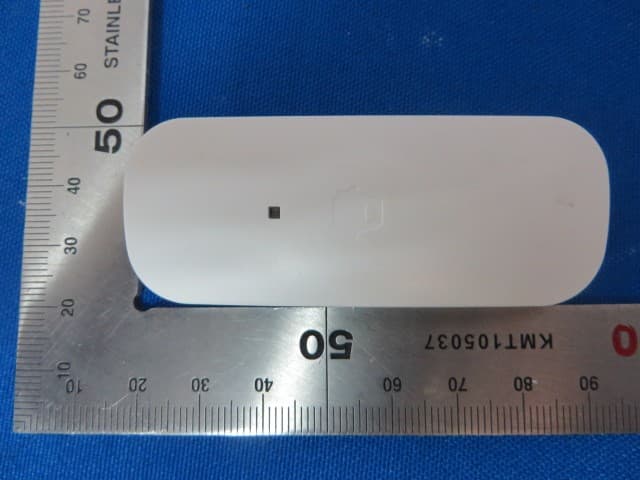
RJYDS2300
Sep 29, 2014Door/Window Contact
Equipment Class
DXX - Part 15 Low Power Communication Device Transmitter