RK41011ENTRY CONTROL BADGE READER
Acroprint Time Recorder Company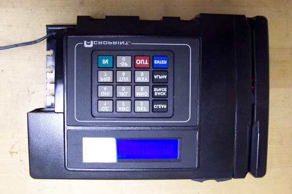
Click to zoom
Application Details
- Equipment Class
- DCD - Part 15 Low Power Transmitter Below 1705 kHz
- Date of Grant
- Nov 17, 2005
- Application Purpose
- Original Equipment
- Date of Application
- Nov 17, 2005
- Equipment Note
- ENTRY CONTROL BADGE READER
- Frequency Range
- 0.12500000 - 0.12500000
- Country
- United States
Documents & Files
Document Text
Text extracted from the exhibit documents filed with the FCC. Open a document above to read the original.
Users Manual
DC7000 Data Collection Ter m i n a l Hardware Manual FCC Warning: Note: This equipment has been tested and found to comply with the limits for a Class A digital device, pursuant to Part 15 of the FCC rules. These limits are designed to provide reasonable protection against harmful interference when the equipment is operated in a commercial environment. This equipment generates, uses, and can radiate radio frequency energy and, if not installed and used in accordance with the instruction manual, may cause harmful interference to radio communications. Operation of this equipment in a residential area is likely to cause harmful interference in which case the user will be required to correct the interference at his or her own expense. Caution: Changes or modifications not expressly approved by the party responsible for compliance could void the user’s authority to operate the equipment. FCC Compliance: (on hardware equipped with modem) This equipment complies with Part 68 of FCC Rules and the requirements adopted by the ACTA. One the rear housing of this equipment is a label that contains, among other information, a product identifier in the format US:AAEQ##TXXXX. If requested this number must be provided to the telephone company. This product uses USOC modular telephone jack: R-J11C A plug and jack used to connect this equipment to the premises wiring and telephone network must comply with the applicable FCC Part 68 rules and requirements adopted by the ACTA. A compliant telephone cord and modular plug is provided with this product. It is designed to be connected to a compatible modular jack that is also compliant. See installation instructions for details. The REN is used to determine the number of devices that may be connected to a telephone line. Excessive RENs on a telephone line may result in the devices not ringing in response to an incoming call. In most but not all areas, the sum of RENs should not exceed five (5.0). To be certain of the number of devices that may be connected to a line, as determined by the total RENs, contact the local telephone company. For products approved after July 23, 2001, the REN for this product is part of the product identifier that has the format US:AAEQ##TXXX. The digits represented by ## are the REN without the decimal point (e.g., 03 is a REN of 0.3). For earlier products, the REN is separately shown on the label. 2 If this equipment, 4G3MM00B1011, causes harm to the telephone network, the telephone company will notify you in advance that temporary discontinuance of service may be required. But if advance notice isn’t practical, the telephone company will notify the customer as soon as possible. Also, you will be advised of your right to file a complaint with the FCC if you believe it is necessary. 3 The telephone company may make changes in its facilities, equipment, operations or procedures that could affect the operation of the equipment. If this happens the telephone company will provide advance notice in order for you to make necessary modifications to maintain uninterrupted service. If trouble is experienced with this equipment, 4G3MM00B1011, for repair or warranty information please contact Acroprint Time Recorder Co. at 800-334-7190. If the equipment is causing harm to the telephone network, the telephone company may request you disconnect the equipment until the problem is resolved. This equipment is of a type that is not intended to be repaired. For service contact Acroprint Time Recorder Co. at 800-334-7190. Connection to party line service is subject to state tariffs. Contact the state public utility commission, public service commission or corporation commission for information. If you have specially wired alarm equipment connected to the telephone line, ensure the installation of this 4G3MM00B1011 does not disable your alarm equipment. If you have questions about what will disable alarm equipment, consult your telephone company or a qualified installer. Canada This Class A digital apparatus complies with Canadian ICES-003. Cet appareil numerique de la classe A est conforme a la norme NMB-003 Du Canada. Lithium Battery Caution: This circuit board on this terminal is populated with a lithium battery to protect data or programs stored in the Random Access Memory (RAM). Do not, under any circumstances, attempt to replace the lithium battery in the terminal. Failure to comply may invalidate your warranty. Battery replacement should be done by qualified personnel wearing the proper eye protection. CAUTION: Danger of explosion if battery is incorrectly replaced. Replace only with the same or equivalent type recommended by the manufacturer. Discard used batteries according to the manufacturer’s instruction. Declaration Of Conformity According To EMC Directive 89/336/EEC We declare under our sole responsibility that the DC7000 magnetic stripe and/or barcode reading and/or data recording equipment to which this declaration relates are in conformity with the following standards: EN55022:1987, EN50082-1, IEC 801-2, IEC 801-3, IEC 801-4, IEC 801-5. I, the undersigned, hereby declare that the equipment specified above conforms to the above directive and standards. Raleigh, North Carolina USA November xx, 2005 W. Glenn Robbins All Rights Reserved. © COPYRIGHT 2005 Acroprint Time Recorder Company 4 Table of Contents 1. Introduction.....................................................................................6 Basic Hardware and Variations.................................................................6 General Specifications...............................................................................6 2. Setup................................................................................................8 Site Requirements......................................................................................8 Unpacking and Inspection.........................................................................8 Mounting.............................…
Text truncated - open the document above for the full version.
Users Manual
c) Proximity Readers Two Proximity Readers are available on the DC7000. The first Proximity Reader uses 125kHz, Read Only, ISO Proximity Card, 64 Bit Encoding (Manchester). Serial Output Data String contains a 9 Bit Header, 40 Bits of Data, 14 Parity Bits and 1 Stop Bit. The second reader is a HID Reader that uses HID Badges: 125kHz, Read Only, H10301 (Std. 26 Bit), Facility Code 101. Note: the reader is not restricted to 26 Bit badges 4. Ports and Connections Ethernet Port The Ethernet port is located on the lower left corner of the terminal. It is a 10 position 8-pin female port, which will accept a male 10/100BASE-T (RJ-45) modular connector. The terminal has the capability to communicate across an intranet, a WAN or the Internet. Indicator Lights Green Wireless RF Activity LED Front Green LED: Ethernet Link Rear Green LED: Ethernet Receive Ethernet PortRS232 Port 12 Wireless WiFi Connection The Wireless Ethernet connection is established via Wireless 802.11b. RS-232 Serial port The RS-232 serial port is located on the lower left corner of the terminal. It is a six position 4-pin female port, which will accept a male RJ-11 modular connector. The DC7000 Terminal can use RS-232 serial communication to connect directly to a host computer. A connection for an IBM ® PC or IBM-PC compatible computer is shown on the following page. 13
Users Manual
NOTE s See Page 24 for USB to RS-232 Adaptor. : Schematic connections are hown from END VIEW (as viewed from the outside of the connectors). Schematic “Standard” Modular Cable (Adaptor A) DB-9 to RJ-11 Adaptor (Use DB-25 RS-232 Host Cable Assy. See pp. 24-25) Cabling to Host Computer with DB-9 Port Schematic NOTE: Schematic connections are shown from END VIEW (as viewed from the outside of the connectors). (Use DB-25 RS-232 Host Cable Assy. See pp. 24-25) Cabling to Host Computer with DB-25 Port Schematic Schematic (Adaptor A) DB-25 to RJ-11 Adaptor 14 Local Area Network: RS-485 Serial Port The RS-485 serial port is located on the lower left corner of the terminal. It is a six position 6-pin female port with the outer 2 pins to Ground. It will accept a male RJ-11 modular connector. The terminal can use RS-485 2-wire serial communication, allowing up to 32 terminals to be connected to one host port. An RS-232 port on the host is typically used in conjunction with an RS-232/RS-485 converter to complete the connection. Through software, the host can communicate with individual terminals even though they are wired in parallel. RS-485 communication uses a differential bus, which provides good protection from interference over long runs of up to 4000 feet. NOTE: When wiring a network, always follow the electric wiring codes in your area. Typically, a Teflon coated wire is required for wiring through the ceiling. The “Daisy Chain” cabling between junction boxes shown on the opposite page is a Teflon jacketed cable. 15 RS-485 Serial Cables Junction Box “Daisy Chain” Wiring Diagram Note: When wiring a network, always follow the electric wiring codes in your area. Typically, a Teflon coated wire is required for wiring through a ceiling. The junction box to junction box wire shown is a teflon jacketed cable. RS485 provides good protection from interference over long runs up to 4000 ft. B RS485 Wiring Diagram The RS485 Serial port is located on the left corner of the terminal. RS485 is imprinted on the terminal casing. RS485 communication allows up to 32 terminals to be connected to one serial port. An RS232 port on the host PC is used with an RS232/RS485 converter to complete the connection. B A A 16 Modem Port The port depicted may have either an RS-485, a Modem, or an Ethernet Communication Device. Terminals, which are equipped with a Modem port, will not have an Ethernet or RS-485 port. The Modem Port is a 6 position 4-pin female port, which will accept a male RJ-11 modular connector. The internal modem (modulator/demodulator) converts electronic data into tones, which are then transmitted over phone lines. Warning: do not plug the modem into a digital phone system because it will damage the modem and void the warranty. 17 Modem Cables Caution – To reduce the risk of fire, use only 26 AWG or larger telecommunication line cord. The cabling for modem operation is typically very simple. The modular connection uses the two inner wires of the RJ-11 jack for “tip” and “ring.” Connect one end of the cable to the terminal and plug the other end into your RJ-11 type modular telephone wall jack. The RJ-11 wall jack should be of the analog telephone type and not a digital network jack. Warning: Connecting to a digital network jack will damage the modem. If a modular wall jack is not available, obtain an adaptor from your local telephone company. . 18
Users Manual
Wand Port The Wand port is located on the left side of the terminal. It is a 6-pin DIN port that accepts a circular DIN connector. The Wand, when connected, uses only 3 of the 6 pins available on the DIN connection. If a Barcode Gun (non-contact reader) is used, the center pin supplies additional power. The terminal uses 2 of the remaining pins as logic lines for external controls. See pin-out and function table below: Pin Function 1 +5 Volts 2 Signal Control Logic Line (Digital IO #0 - Output Only) 3 Barcode Wand Receive Data 4 Ground 5 Access Logic Line (Digital IO #1 - Output Only) 6 12 Volt Unregulated (Maximum current draw 220 mA with 3A Transformer Only) 19 Wand and Y-Cable Disconnect power to the terminal before connecting the Barcode Wand. The wand is capable of reading bar code stripes by passing it directly over the label. Check the software manual to identify the codes your terminal will read. The Y-cable shown below allows for connection of both a wand and other external devices. The single end of the cable is plugged into the terminal. A wand can be connected to one split and another device to the other. See appendix for External Relay Box part number. Y-cable (splitter) Barcode Wand 20 Parallel Port The parallel port is located on the right back of the DC7000 Terminal. It is a 25 pin female port, which will accept a 25-pin male connector . This type of parallel port is typically used on IBM ® PC or IBM-PC compatible computers. The DC7000 Terminal provides strain relief if the connector is locked in by the securing screws. Securing the parallel cable to the wall or mounting surface can obtain additional strain relief. 21 Parallel Cable The parallel port is used for additional digital I/O or for printing. A standard parallel print cable is used with a simple ASCII parallel printer. Shown below is a parallel interface cable. Since this is the same cable that is used to connect an IBM-PC or compatible to a printer, it will likely be available from most computer dealers off-the-shelf. One end is a male DB-25 connector; the other end is a 36-pin Centronics-type connector to match the parallel port on the printer. Note: Schematic connections are shown from END VIEW. (As viewed from the outside of the connectors.) 22 Parallel Cable Schematic 5. CompanionProducts Readers Description / Illustration Part Number Barcode Wand 74-0106-002 and Holder External Visible 74-0111-000 Barcode Infrared 74-0111-002 Slot Reader Power Supplies Description/Illustration Part Number Lighter Power 72-0160-000 12 VDC Adaptor 120VAC to 9VAC, 1A 56-0113-000 Power Supply 120/240VAC to 12VAC, 3A 56-0128-000 Power Supply (Required for Terminals with Fingerprint Reader, Modem or Wireless Communication) Note: Comes with Std. 2-Blade US Plug 75-0166-000 Optional Available Adaptors Continental Europe 75-0167-000 U.K. / Ireland 75-0168-000 Australia / New Zealand 75-0169-000 S.Africa / India 75-0170-000 23 External Relay Box, External Buzzer External Relay Box 120 V 01-0121-000 240 V 01-0121-002 External Buzzer 01-0122-000 24 Cables Description/Illustration Part Number “Standard” Modular Cable length - 7 feet 72-0146-000 - 50 feet 72-0146-004 Y-Cable (splitter) 72-0159-000 DB-25 RS-232 Host Cable Assembly Includes DB-25 Female (RS-232/host) to RJ-11 Female adaptor and “Standard” Modular Cable. length - 7 feet 25-0116-000 - 50 feet 25-0116-007 DB-9 RS-232 Host Cable Assembly Includes DB-9 (RS-232/host) to RJ-11 female adaptor and “Standard” Modular Cable. length - 7 feet 25-0116-004 - 50 feet 25-0116-008 9 Pin RS-232 to USB Adaptor 63-0181-000 25 Cables, Converter, Badge Racks Description / Illustration Modem Adaptor Cable Assembly Includes DB-25 Male (modem) to RJ-11 male adaptor and “Standard” Modular Cable. length - 7 feet 25-0123-000 Teflon Cable (available by the foot) 55-0124-000 Junction Box 63-0169-000 RS-232 to RS-485 Converter Assembly Includes RS-232 to RS-485 converter with DB-9 / RJ-11 Connectors and “Standard” Modular Cable. length - 7 feet 25-0134-001 40 Pocket Badge Rack (Plastic) 81-0117-000 (8¼" wide x 22 5 / 8 ” high) (2) 12 Pocket Badge Racks (Plastic) 81-0116-003 (3 7 / 8 " wide x 14" high) 40 Pocket Badge Rack (Metal) 81-0113-000 (4 1 / 2 " wide x 32" high) 26 6. Appendix Units with Acroprint Data Collection Firmware Acroprint Data Collection Terminal Setup Instructions Configuring procedure for entering the DATE & TIME: Swipe the Configuration Badge 000000000 (This badge is provided with each terminal) Select option 1 for DATE <Press ENTER> Select the Day, Month, Year DDMMYYYY <Press ENTER> Select the Time HH:MM <Press ENTER> (Time is entered in military time, 2:00 pm = 14:00) Configuring procedure for selecting PORTS: Swipe the Configuration Badge 000000000 (This badge is provided with each terminal.) Select option 2 for Ports <press ENTER> Select option 0 for RS232 <press ENTER> Select the baud rate 0 for 1200, 1 for 2400, 2 for 4800, 3 for 9600 and 4 for 19,200 baud. <press ENTER> (For modem terminal only) Select option 1 for Modem <press ENTER> Select the Modem baud. <press ENTER> Select the Answer Window HHMMHHMM for starting and ending times < press ENTER> (time is in military format, Example: Clock will not answer during business hours and only answer between the hours of 8:00 pm and 6:00 am, then select 20000600.) 27 (For RS485 terminals only) Select option 1 for RS485 <press ENTER> Select the baud rate 0 for 1200, 1 for 2400, 2 for 4800, 3 for 9600 and 4 for 19,200 baud. <press ENTER> (For Ethernet terminals only) Select option 2 for Ethernet <press ENTER> Select the baud rate option 3 for 9600 baud <press ENTER> (Leave this as the default for Ethernet.) Select the TCPIP address <press ENTER> (Your network administrator will have this information.) Select the GATEWAY address <press ENTER> (Your network administrator will have this information.) Select the PORT VALUE <press ENTER> (Default number 10001. Select the save value in the ATR9800 software.) Select the NETMASK PART BITS NUMB…
Text truncated - open the document above for the full version.
ID Label/Location Info
PRODUCT LABEL LOCATION WITH FCC ID(s) ACROPRINT TIME RECORDER CO. DC 7000 LABEL LOCATION 03/11/05
Test Report
M. Flom Associates, Inc. 3356 N. San Marcos Place, Suite 107 Chandler, Arizona 85225-7176 FCC ID: RK41011 (480) 926-3100 phone, fax (480) 926-3598 MFA p0560011, d0560049 Transmitter Certification of FCC ID: RK41011 Equipment: Entry Control Badge Reader to Federal Communications Commission Rule Part 15.209 Date of report: June 28, 2005; Amended November 16, 2005 On the Behalf of the Applicant: Acroprint Time Recorder Company At the Request of: Acroprint Time Recorder Company 5640 Departure Drive Raleigh, NC 27616 Attention of: Mark Lackey [email protected] 800-334-7190 ext. 138; Fax 919-872-3778 Supervised By: Michael Findley, Laboratory Manager M. Flom Associates, Inc. 3356 N. San Marcos Place, Suite 107 Chandler, Arizona 85225-7176 FCC ID: RK41011 (480) 926-3100 phone, fax (480) 926-3598 MFA p0560011, d0560049 List Of Exhibits (FCC Certification (Transmitters) - Revised 9/28/98) Applicant: Acroprint Time Recorder Company FCC ID: RK41011 By Applicant: 1. Letter Of Authorization 2. Identification Drawings Label Location of Label Compliance Statement Location of Compliance Statement 3. Documentation: 2.1033(B) (3) User Manual (4) Operational Description (5) Block Diagram (5) Schematic Diagram (7) Photographs Parts List Active Devices By M.F.A. Inc. A. Testimonial & Statement of Certification M. Flom Associates, Inc. 3356 N. San Marcos Place, Suite 107 Chandler, Arizona 85225-7176 FCC ID: RK41011 (480) 926-3100 phone, fax (480) 926-3598 MFA p0560011, d0560049 The Applicant has been cautioned as to the following: 15.21 Information to User. The users manual or instruction manual for an intentional radiator shall caution the user that changes or modifications not expressly approved by the party responsible for compliance could void the user's authority to operate the equipment. 15.27(a) Special Accessories. Equipment marketed to a consumer must be capable of complying with the necessary regulations in the configuration in which the equipment is marketed. Where special accessories, such as shielded cables and/or special connectors are required to enable an unintentional or intentional radiator to comply with the emission limits in this part, the equipment must be marketed with, i.e. shipped and sold with, those special accessories. However, in lieu of shipping or packaging the special accessories with the unintentional or intentional radiator, the responsible party may employ other methods of ensuring that the special accessories are provided to the consumer, without additional charge. Information detailing any alternative method used to supply the special accessories for a grant of equipment authorization or retained in the verification records, as appropriate. The party responsible for the equipment, as detailed in § 2.909 of this chapter, shall ensure that these special accessories are provided with the equipment. The instruction manual for such devices shall include appropriate instructions on the first page of text concerned with the installation of the device that these special accessories must be used with the device. It is the responsibility of the user to use the needed special accessories supplied with the equipment. M. Flom Associates, Inc. 3356 N. San Marcos Place, Suite 107 Chandler, Arizona 85225-7176 FCC ID: RK41011 (480) 926-3100 phone, fax (480) 926-3598 MFA p0560011, d0560049 Table Of Contents Rule Description Page . Test Report 1 . Expository Statement 2 2.1033(c) General Information Required 3 . Standard Test Conditions and Engineering Practices 6 2.1053(a) Field Strength of Spurious Radiation 7 15.207 A/C Powerline Conducted Emissions 12 M. Flom Associates, Inc. 3356 N. San Marcos Place, Suite 107 Page 1 of 14 Chandler, Arizona 85225-7176 FCC ID: RK41011 (480) 926-3100 phone, fax (480) 926-3598 MFA p0560011, d0560049 Required information per ISO/IEC Guide 25-1990, paragraph 13.2: a) Test Report b) Laboratory: (FCC: 31040/SIT) (Canada: IC 2044) M. Flom Associates, Inc. 3356 N. San Marcos Place, Suite 107 Chandler, AZ 85225 c) Report Number: d0560049 d) Client: Acroprint Time Recorder Company 5640 Departure Drive Raleigh, NC 27616 e) Identification: FCC ID: RK41011 Model DC7000 Description: Entry Control Badge Reader f) EUT Condition: Not required unless specified in individual tests. g) Report Date: June 28, 2005 EUT Received: June 20, 2005 h, j, k): As indicated in individual tests. i) Sampling method: No sampling procedure used. l) Uncertainty: In accordance with MFA internal quality manual. m) Supervised by: Michael Findley, Laboratory Manager n) Results: The results presented in this report relate only to the item tested. o) Reproduction: This report must not be reproduced, except in full, without written permission from this laboratory. M. Flom Associates, Inc. 3356 N. San Marcos Place, Suite 107 Page 2 of 14 Chandler, Arizona 85225-7176 FCC ID: RK41011 (480) 926-3100 phone, fax (480) 926-3598 MFA p0560011, d0560049 Expository Statement Applicant: Acroprint Time Recorder Company FCC ID: RK41011 The applicant has designed a device that can be sold in several different formats. Some of the formats are purely passive requiring only 47CFR15.107 / 109 testing, a Declaration of Conformance, and the appropriate label. In that form the EUT may contain a Finger Print Reader / Magnetic Stripe Reader / Barcode Reader Wand either singly or in combination This report shows the tests conducted on a unit fitted with the above options and a Proximity Badge Reader. The Badge Reader is an intentional radiator under 47CFR15.209 Field Disturbance Sensor and is available in two forms, the ISO Reader and the HID Reader. Both these devices occupy the same area of the motherboard and are mutually exclusive. The circuitry for the ISO is populated on the motherboard when used; the HID reader is on a separate header board that sits over the unpopulated ISO Reader area. The same loop antenna is used with either of the installed readers. A variant of the basic device contains a telephone modem …
Text truncated - open the document above for the full version.
Test Setup Photos
M. Flom Associates, Inc. 3356 N. San Marcos Place, Suite 107 Page 11 of 14 Chandler, Arizona 85225-7176 FCC ID: RK41011 (480) 926-3100 phone, fax (480) 926-3598 MFA p0560011, d0560049 Radiated Setup
Contact Information
Applicant
Mark C Lackey(Project Engineer)
Test Firm
M. Flom Associates, Inc.Morton Flom
Technical Specifications
| # | Rule Parts | Frequency Range | Power Output |
|---|---|---|---|
| 1 | 15C | 0.125 MHz - 0.125 MHz | - |
Other Applications from Acroprint Time Recorder Company
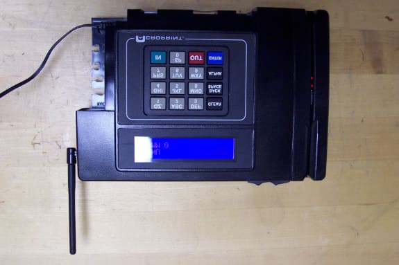
RK41012
Nov 17, 2005ENTRY CONTROL BADGE READER
Equipment Class
DCD - Part 15 Low Power Transmitter Below 1705 kHz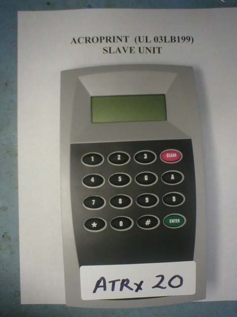
RK41207
Dec 16, 2003Proximity Reader
Equipment Class
DCD - Part 15 Low Power Transmitter Below 1705 kHz