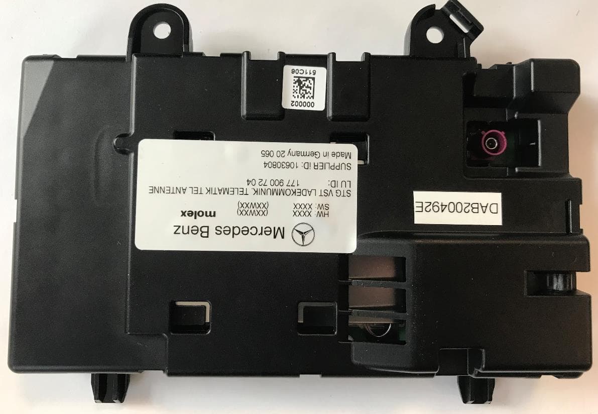
RK7MBC-NAR2Wideband Consumer Signal Booster
Molex Technologies GmbH
Click to zoom
Application Details
- Equipment Class
- B2W - Part 20 Wideband Consumer Booster (CMRS)
- Date of Grant
- Apr 05, 2020
- Application Purpose
- Original Equipment
- Date of Application
- Apr 05, 2020
- Equipment Note
- Wideband Consumer Signal Booster
- Frequency Range
- 777.00000000 - 787.00000000
- Company
- Molex Technologies GmbH
- Country
- Germany
Documents & Files
Document Text
Text extracted from the exhibit documents filed with the FCC. Open a document above to read the original.
Users Manual
ENGLISH Version FCC/ISED Notice: This is a CONSUMER device. • BEFORE USE, you MUST REGISTER THIS DEVICE with your wireless provider and have your provider ́s consent. Most wireless providers consent to the use of signal boosters. Some providers may not consent to the use of this device on their network. If you are unsure, contact your provider. • In Canada, BEFORE USE, you must meet all requirements set out in ISED CPC-2-1-05 • You MUST operate this device with approved antennas and cables as specified by the manufacturer. Antennas MUST be installed at least 20 cm (8 inches) from any person. • You MUST cease operating this device immediately if requested by the FCC (or ISED in Canada) or a licensed wireless service provider. • WARNING. E911 location information may not be provided or may be inaccurate for calls served by using this device. Link to ISED CPC-2-1-05: https://www.ic.gc.ca/eic/site/smt-gst.nsf/eng/h_sf06136.html ➔ CPC-2-1-05 - Zone Enhancers FCC RF Exposure Statement This equipment complies with FCC radiation exposure limits set forth for an uncontrolled environment. End users must follow the specific operating instruction for satisfying RF exposure compliance. This transmitter must not be co-located or operating in conjunction with any other antenna or transmitter. Any changes or modifications not expressly approved by Molex could void the user's authority to operate this equipment. FCC ID: RK7MBC-NAR2 IC 4774A-MBCNAR2 FRENCH Version Pour les enrichisseurs de zone de consommation: Ce produit est un appareil de CONSOMMATION. • AVANT DE L’UTILISER, vous DEVEZ conformer à toutes les exigences établies dans la CPC-2-1- 05. • Vous DEVEZ utiliser cet appareil avec des antennes et des câbles approuvés, conformément aux indications du fabricant. Les antennes DOIVENT être installées à au moins 20 cm d’une personne. • Vous DEVEZ cesser d’utiliser cet appareil immédiatement à la demande d’ISDE ou d’un fournisseur de services sans fil autorisé. • AVERTISSEMENT: Les renseignements relatifs à l’emplacement du service E911 pourraient être non fournis ou inexacts pour les appels effectués au moyen de cet appareil. lien vers la CPC-2-1-05 d’ISDE: https://www.ic.gc.ca/eic/site/smt-gst.nsf/fra/h_sf06136.html ➔ CPC-2-1-05 - Enrichisseurs de zone Les changements ou modifications non approuvés expressément par Molex peuvent entraîner la caducité de l’autorisation d’utiliser l’équipement. FCC ID: RK7MBC-NAR2 IC 4774A-MBCNAR2
Users Manual
This Signal Booster fulfills the FCC requirements for the Network Protection Standard (NPS). It incorporates features to prevent harmful interference to wireless networks like: - Anti-oscillation to detect and mitigate any unintended oscillations in uplink and downlink frequency bands, - Adaptive gain control with self-monitoring and to power down automatically as approaching any affected base station, - Uplink Inactivity to shut down the transmit amplifiers if not serving an active device connection. This Signal Booster includes features to prevent harmful interference. These features are enabled and operating at all times the signal booster is in use, they may not be deactivated by the operator.
External Photos
Company Confidential Copyright© 2020 MolexCVS Dabendorf GmbH 1(4) Exhibit 14 RK7MBC-NAR2 External Photographs RK7MBC-NAR2 4774A-MBCNAR2 Company Confidential Copyright© 2020 MolexCVS Dabendorf GmbH 2(4) Top View (HVIN: 17400213, 17401213, 17400214) Bottom View (HVIN: 17400213, 17400214) Company Confidential Copyright© 2020 MolexCVS Dabendorf GmbH 3(4) Top View (HVIN: 17401213) External Adapter only Company Confidential Copyright© 2020 MolexCVS Dabendorf GmbH 4(4) Top View (HVIN 17402213) Bottom View (HVIN 17402213)
ID Label/Location Info
Company Confidential Copyright© 2019 MolexCVS Dabendorf GmbH 1(1) ID Label and Location FCC ID: RK7MBC-NAR2 ISED: 4774A-MBCNAR2 The Label is attached on the top cover of all Compenser variants.
RF Exposure Info
Test Laboratory: 7layers GmbH Borsigstraße 11 40880 Ratingen Germany Note: The following test results relate only to the devices specified in this document. This report shall not be reproduced in parts without the written approval of the test laboratory. 7layers GmbH Registergericht registered in: Borsigstraße 11 Geschäftsführer / Düsseldorf, HRB 75554 40880 Ratingen, Germany Managing Directors: USt-IdNr VAT No.: T +49 (0) 2102 749 0 Frank Spiller DE203159652 F +49 (0) 2102 749 350 Bernhard Retka TAX No. 147/5869/0385 www.7layers.com Alexandre Norré-Oudard A Bureau Veritas Group Company RF Exposure Evaluation For LTE‐MBC‐NAR2 FCC ID:RK7MBC‐NAR2 IC ID:4774A‐MBCNAR2 Assessment Reference: MDE_MOLEX_1901_MPEa_rev01 Assessment Reference: MDE_MOLEX_1901_MPEa_rev01 Page 2 of 8 Table of Contents 0 Summary 3 0.1 Technical Report Summary 3 1 Administrative Data 4 1.1 Testing Laboratory 4 1.2 Project Data 4 1.3 Applicant Data 4 1.4 Manufacturer Data 4 2 Test object Data 5 2.1 General EUT Description 5 2.2 Equipment under test details 5 2.3 General note 5 3 Evaluation Results 6 3.1 RF Exposure Evaluation 6 Assessment Reference: MDE_MOLEX_1901_MPEa_rev01 Page 3 of 8 0 Summary 0.1 Technical Report Summary Ty pe of Report RF Exposure Assessment for a GSM/UMTS/LTE Compenser. Applicable FCC and ISED Rules For RF Exposure: OET Bulletin 65 Edition 97‐01 August 1997 FCC 47 CFR §1.1307 FCC 47 CFR §1.1310 RSS‐102 Issue 5 – March 2015 Report version control Rev Version Release date Changes Version validity ‐ 31.01.2020 Initial version Valid 01 12.03.2020 Included calculation for GSM 50% Duty Cycle Valid Reviewer: Responsible for Report: Assessment Reference: MDE_MOLEX_1901_MPEa_rev01 Page 4 of 8 1 Administrative Data 1.1 Testing Laboratory Company Name: 7layers GmbH Address Borsigstr. 11 40880 Ratingen Germany The test facility is also accredited by the following accreditation organisation: Laboratory accreditation no.: DAkkS D‐PL‐12140‐01‐01| D‐PL‐12140‐01‐02 | D‐PL‐ 12140‐01‐03 FCC Designation Number: DE0015 FCC Test Firm Registration: 929146 ISED CAB IdentifierDE0007; ISED#: 3699A Report Template Version: 30.01.2020 1.2 Project Data Responsible for assessment and report:Mr. Patrick Lomax Date of Report: 12.03.2020 1.3 Applicant Data Company Name: Molex CVS Dabendorf GmbH Address: Märkische Strasse 72 Zossen Germany Contact Person: Email: Ines Baufeld [email protected] 1.4 Manufacturer Data Company Name: please see applicant data Contact Person: Email: Sebastian Dern [email protected] Assessment Reference: MDE_MOLEX_1901_MPEa_rev01 Page 5 of 8 2 Test object Data 2.1 General EUT Description Equipment under Test LTE‐MBC‐NAR2 Type Designation: 17400213 Kind of Device: Multi Band Compenser FCC ID: RK7MBC‐NAR2 IC Number: 4774A‐MBCNAR2 General product description: The EUT is a Multi Band Compenser for automotive use. See the below section for all variants to which the report shall apply. 2.2 Equipment under test details Description Equipment under Test Type Number Serial Number HW Status SW Status Multi Band Compenser LTE‐MBC‐NAR2 17400213 *0D0FKW‐ 00117.01.20 98210011* HW004 0003 The below Variant models are declared by the manufacturer as electrically identical but have not been tested. Product name Product Type number LTE‐MBC‐NAR2 17401213 LTE‐MBC‐NAR2 17400214 LTE‐MBC‐NAR2 17402213 2.3 General note Note 1. Per the KDB 935210 related consumer and industrial signal boosters that operate under Parts 20, 22, 24, 27, and 90 of the FCC rules, the input signaling shall be tested to Pulsed CW (12.5% Duty Cycle)to represent GSM technologies and AWGN (100% Duty Cycle) to represent CDMA technologies (UMS/LTE). Assessment Reference: MDE_MOLEX_1901_MPEa_rev01 Page 6 of 8 3 Evaluation Results 3.1 RF Exposure Evaluation Standards OET Bulletin 65 Edition 97‐01 August 1997 RSS‐102 Issue 5 – March 2015 3.1.1 Test limits As specified in Table 1B of 47 CFR 1.1310 – Limits for Maximum Permissible Exposure (MPE), Limits for General Population/Uncontrolled Exposure. Frequency range (MHz)Power density (mW/cm²) 300 –1,500f/1500 1,500 –100,0001.0 Limits specified per RSS‐102, Issue 5. Frequency range (MHz) Power density (W/m²)Power density (mW/cm²) 300 – 6000 0.02619 f 0.6834 mW/cm² = W/m² * 0.1 Equation OET bulletin 65, page 18, edition 97‐01: 푆ൌ ீ ସగோ మ ൌ ாூோ ସగோ² Where: S = power density P = power input to the antenna G = power gain of the antenna in the direction of interest relative to an isotropic radiator R = distance to the centre of radiation of the antenna Assessment Reference: MDE_MOLEX_1901_MPEa_rev01 Page 7 of 8 3.1.2 Test Protocol Maximum antenna gain to comply with MPE limits for Industry Canada Band Mode Duty Cycle Frequency (MHZ) Maximum Conducted output power (dBm) Maximum Conducted output power (mW) Equivalent conducted output power (mW) MPE Limit (mW/cm²) Maximum antenna gain to meet MPE Limit (dBi) Separation distance (cm) 850 GSM 12.5% 834.0 22.0 158.49 19.82 0.2597 18.2 20 1900 GSM 12.5% 1865.0 21.5 141.25 17.66 0.4501 21.1 20 850 GPRS 50.0% 834.022.0 158.49 79.25 0.2597 12.220 1900 GPRS 50.0% 1865.0 21.5 141.25 70.63 0.4501 15.1 20 FDD 2 UMTS 100% 1865.0 19.8 95.50 95.50 0.4501 13.7 20 FDD 4 UMTS 100% 1719.0 20.0 100.00 100.00 0.4257 13.3 20 FDD 5 UMTS 100% 834.019.9 97.72 97.72 0.2597 11.320 eFDD 2 LTE 100% 1865.0 19.8 95.50 95.50 0.4501 13.7 20 eFDD 4 LTE 100% 1719.0 20.0 100.00 100.00 0.4257 13.3 20 eFDD 5 LTE 100% 834.0 19.9 97.72 97.72 0.2597 11.3 20 eFDD 13 LTE 100% 780.0 19.7 93.33 93.33 0.2481 11.3 20 eFDD 17 LTE 100% 709.0 20.0 100.00 100.00 0.2324 10.7 20 eFDD 12 LTE 100% 709.0 20.0 100.00 100.00 0.2324 10.7 20 Maximum antenna gain to comply with MPE limits for FCC Band Mode Duty Cycle Frequency (MHZ) Maximum Conducted output power (dBm) Maximum Conducted output power (mW) Equivalent conducted output power (mW) MPE Limit (mW/cm²) Maximum antenna gain to meet MPE Limit (dBi) Separation distance (cm) 850 GSM 12.5% 834.0 22 158.49 19.82 0.5560 21.5 20 1900 GSM 12.5% 1865.0 21.5 141.25 17.66 …
Text truncated - open the document above for the full version.
Test Report
Test Laboratory: 7layers GmbH Borsigstrasse 11 40880 Ratingen Germany Note: The following test results relate only to the devices specified in this document. This report shall not be reproduced in parts without the written approval of the test laboratory. 7layers GmbH Geschäftsführer/ Borsigstraße 11 Managing Directors: Registergericht/registered: a Bureau Veritas 40880 Ratingen, Germany Frank Spiller Düsseldorf HRB 75554 Group Company T +49 (0) 2102 749 0 Bernhard Retka USt-Id.-Nr./VAT-No. DE203159652 F +49 (0) 2102 749 350 Alexandre Norré-Oudard Steuer-Nr./TAX-No. 147/5869/0385 www.7layers.com Commerzbank AG Account No. 303 016 000 Bank Code 300 400 00 IBAN DE81 3004 0000 0303 0160 00 Swift Code COBADEFF FCC Measurement/Technical Report on NAR Compenser LTE-MBC-NAR2 FCC ID: RK7MBC-NAR2 IC: 4774A-MBCNAR2 Test Report Reference: MDE_MOLEX_1901_FCC_01_rev01 TEST REPORT REFERENCE: MDE_MOLEX_1901_FCC_01_rev01 Page 2 of 215 Table of Contents 1 Applied Standards and Test Summary 4 1.1 Applied Standards 4 1.2 FCC-IC Correlation Table 5 1.3 Measurement Summary / Signatures 6 2 Revision History 14 3 Administrative Data 15 3.1 Testing Laboratory 15 3.2 Project Data 15 3.3 Applicant Data 15 3.4 Manufacturer Data 16 4 Test object Data 17 4.1 General EUT Description 17 4.2 EUT Main components 18 4.3 Ancillary Equipment 18 4.4 Auxiliary Equipment 18 4.5 EUT Setups 19 4.6 Operating Modes 19 4.7 Product labelling 19 5 Test Results 20 5.1 Authorized Frequency Band 20 5.2 Maximum Power 28 5.3 Maximum Booster Gain 49 5.4 Intermodulation 52 5.5 Out-of -band Emission 61 5.6 Conducted Spurious Emissions 96 5.7 Maximum Transmitter Noise Power 107 5.8 Variable Uplink Noise Timing 116 5.9 Uplink Inactivity 122 5.10 Variable Booster Gain 127 5.11 Variable Uplink Gain Timing 133 5.12 Occupied Bandwidth 138 5.13 Oscillation Restart 171 5.14 Oscillation Shutdown or Mitigation 184 5.15 Radiated Spurious Emissions 189 6 Test Equipment 205 7 Antenna Factors, Cable Loss and Sample Calculations 208 7.1 LISN R&S ESH3-Z5 (150 kHz – 30 MHz) 208 TEST REPORT REFERENCE: MDE_MOLEX_1901_FCC_01_rev01 Page 3 of 215 7.2 Antenna R&S HFH2-Z2 (9 kHz – 30 MHz) 209 7.3 Antenna R&S HL562 (30 MHz – 1 GHz) 210 7. 4 Antenna R&S HF907 (1 GHz – 18 GHz) 211 7.5 Antenna EMCO 3160-09 (18 GHz – 26.5 GHz) 212 7.6 Antenna EMCO 3160-10 (26.5 GHz – 40 GHz) 213 8 Measurement Uncertainties 214 9 Photo Report 215 TEST REPORT REFERENCE: MDE_MOLEX_1901_FCC_01_rev01 Page 4 of 215 1 APPLIED STANDARDS AND TEST SUMMARY 1.1 APPLIED STANDARDS Type of Authorization Certification for an Wideband Consumer signal Booster. Applicable FCC Rules Prepared in accordance with the requirements of FCC Rules and Regulations as listed in 47 CFR Ch.1 Parts 2 and 20, 22, 24, 27 (10-1-18 Edition). The following subparts are applicable to the results in this test report. Part 2, Subpart J - Equipment Authorization Procedures, Certification Part 20, Commercial Mobiles Serviced § 20.21 Signal Boosters Part 22, Subpart H – Cellular Radiotelephone Service § 22.905 – Channels for cellular service § 22.913 – Effective radiated power limits § 22.917 – Emission limitations for cellular equipment Part 24 E – Personal Communication Services § 24.229 - Frequencies § 24.232 – Power and antenna height limits § 24.238 – Emission limitations for Broadband PCS equipment Part 27 – Miscellaneous Wireless Communication Services § 27.5 (b), (c) - Frequencies § 27.50 (b) (c) – Power limits and duty cycle § 27.53 (c), (f), (g), (h) – Emission limits The tests were selected and performed with reference to the FCC Public Notice 935210 applying “Wideband Consumer Signal Booster Compliance Measurement Guidance” 935210 D03 v04r03, 2019-04-15. TEST REPORT REFERENCE: MDE_MOLEX_1901_FCC_01_rev01 Page 5 of 215 Summary Test Results: The EUT complied with all performed tests as listed in chapter 1.3 Measurement Summary / Signatures. 1.2 FCC-IC CORRELATION TABLE FCC-ISED Correlation of measurement requirements for Wideband Consumer Signal Booster from FCC and ISED Canada Measurement FCC reference ISED reference Anti-oscillation §20.21(e)(8)(ii)(A) §20.21(e)(5) RSS-131 Issue 3: 5.1.1.1 Gain control §20.21(e)(8)(ii)(B) RSS-131 Issue 3: 5.1.1.2 Power down §20.21(e)(8)(i)(H) RSS-131 Issue 3: 5.1.1.3 Interference avoidance for wireless subsystems §20.21(e)(8)(ii)(C) RSS-131 Issue 3: 5.1.1.4 Bidirectional capability §20.21(e)(8)(i)(B) RSS-131 Issue 3: 5.1.2 Noise limits §20.21(e)(8)(i)(A) RSS-131 Issue 3: 5.1.3.1 Gain limits §20.21(e)(8)(i)(C)(1) RSS-131 Issue 3: 5.1.3.2 Power limits §20.21(e)(8)(i)(D) RSS-131 Issue 3: 5.1.3.3 Out-of -band emission limits §20.21(e)(8)(i)(E) RSS-131 Issue 3: 5.1.3.4 Intermodulation limits §20.21(e)(8)(i)(F) RSS-131 Issue 3: 5.1.3.5 Transmit power off mode §20.21(e)(8)(i)(H) RSS-131 Issue 3: 5.1.3.6 Uplink inactivity §20.21(e)(8)(i)(I) RSS-131 Issue 3: 5.1.3.7 TEST REPORT REFERENCE: MDE_MOLEX_1901_FCC_01_rev01 Page 6 of 215 1.3 MEASUREMENT SUMMARY / SIGNATURES 47 CFR CHAPTER I FCC PART 20 §20.21 § 20.21 (e)(3) Frequency Bands Authorized Frequency Band The measurement was performed according to KDB 935210 D03 Final Result OP-Mode Frequency Band, Direction Setup Date FCC ISED Band 12, Downlink S01_AA01 2020-01-20 Performed Performed Band 12, Uplink S01_AA01 2020-01-20 Performed Performed Band 13, Downlink S01_AA01 2020-01-20 Performed Performed Band 13, Uplink S01_AA01 2020-01-20 Performed Performed Band 2, Downlink S01_AA01 2020-01-20 Performed Performed Band 2, Uplink S01_AA01 2020-01-20 Performed Performed Band 4, Downlink S01_AA01 2020-01-20 Performed Performed Band 4, Uplink S01_AA01 2020-01-20 Performed Performed Band 5, Downlink S01_AA01 2020-01-20 Performed Performed Band 5, Uplink S01_AA01 2020-01-20 Performed Performed 47 CFR CHAPTER I FCC PART 20 §20.21 § 20.21 (e)(8)(i)(D) Power Limits; § 20.21 (e)(8)(i)(B) Bidirectional Capability Maximum Power The measurement was performed according to KDB 935210 D03 Final Result OP-Mode Frequency Band, Direction, Signal Type Setup Date FCC …
Text truncated - open the document above for the full version.
Test Report
TEST REPORT REFERENCE: MDE_MOLEX_1901_FCC_01_rev01 Page 74 of 215 Frequency Band = Band 5, Direction = Downlink, Signal Type = LTE, Band Edge = lower (S01_AA01) Frequency Band = Band 5, Direction = Downlink, Signal Type = CDMA, Band Edge = lower (S01_AA01) TEST REPORT REFERENCE: MDE_MOLEX_1901_FCC_01_rev01 Page 75 of 215 Frequency Band = Band 12, Direction = Downlink, Signal Type = GSM, Band Edge = upper (S01_AA01) Frequency Band = Band 12, Direction = Downlink, Signal Type = LTE, Band Edge = upper (S01_AA01) TEST REPORT REFERENCE: MDE_MOLEX_1901_FCC_01_rev01 Page 76 of 215 Frequency Band = Band 12, Direction = Downlink, Signal Type = CDMA, Band Edge = upper (S01_AA01) Frequency Band = Band 12, Direction = Downlink, Signal Type = GSM, Band Edge = lower (S01_AA01) TEST REPORT REFERENCE: MDE_MOLEX_1901_FCC_01_rev01 Page 77 of 215 Frequency Band = Band 12, Direction = Downlink, Signal Type = LTE, Band Edge = lower (S01_AA01) Frequency Band = Band 12, Direction = Downlink, Signal Type = CDMA, Band Edge = lower (S01_AA01) TEST REPORT REFERENCE: MDE_MOLEX_1901_FCC_01_rev01 Page 78 of 215 Frequency Band = Band 13, Direction = Downlink, Signal Type = GSM, Band Edge = upper (S01_AA01) Frequency Band = Band 13, Direction = Downlink, Signal Type = LTE, Band Edge = upper (S01_AA01) TEST REPORT REFERENCE: MDE_MOLEX_1901_FCC_01_rev01 Page 79 of 215 Frequency Band = Band 13, Direction = Downlink, Signal Type = CDMA, Band Edge = upper (S01_AA01) Frequency Band = Band 13, Direction = Downlink, Signal Type = GSM, Band Edge = lower (S01_AA01) TEST REPORT REFERENCE: MDE_MOLEX_1901_FCC_01_rev01 Page 80 of 215 Frequency Band = Band 13, Direction = Downlink, Signal Type = LTE, Band Edge = lower (S01_AA01) Frequency Band = Band 13, Direction = Downlink, Signal Type = CDMA, Band Edge = lower (S01_AA01) TEST REPORT REFERENCE: MDE_MOLEX_1901_FCC_01_rev01 Page 81 of 215 Frequency Band = Band 2, Direction = Uplink, Signal Type = GSM, Band Edge = upper (S01_AA01) Frequency Band = Band 2, Direction = Uplink, Signal Type = LTE, Band Edge = upper (S01_AA01) TEST REPORT REFERENCE: MDE_MOLEX_1901_FCC_01_rev01 Page 82 of 215 Frequency Band = Band 2, Direction = Uplink, Signal Type = CDMA, Band Edge = upper (S01_AA01) Frequency Band = Band 2, Direction = Uplink, Signal Type = GSM, Band Edge = lower (S01_AA01) TEST REPORT REFERENCE: MDE_MOLEX_1901_FCC_01_rev01 Page 83 of 215 Frequency Band = Band 2, Direction = Uplink, Signal Type = LTE, Band Edge = lower (S01_AA01) Frequency Band = Band 2, Direction = Uplink, Signal Type = CDMA, Band Edge = lower (S01_AA01) TEST REPORT REFERENCE: MDE_MOLEX_1901_FCC_01_rev01 Page 84 of 215 Frequency Band = Band 4, Direction = Uplink, Signal Type = GSM, Band Edge = upper (S01_AA01) Frequency Band = Band 4, Direction = Uplink, Signal Type = LTE, Band Edge = upper (S01_AA01) TEST REPORT REFERENCE: MDE_MOLEX_1901_FCC_01_rev01 Page 85 of 215 Frequency Band = Band 4, Direction = Uplink, Signal Type = CDMA, Band Edge = upper (S01_AA01) Frequency Band = Band 4, Direction = Uplink, Signal Type = GSM, Band Edge = lower (S01_AA01) TEST REPORT REFERENCE: MDE_MOLEX_1901_FCC_01_rev01 Page 86 of 215 Frequency Band = Band 4, Direction = Uplink, Signal Type = LTE, Band Edge = lower (S01_AA01) Frequency Band = Band 4, Direction = Uplink, Signal Type = CDMA, Band Edge = lower (S01_AA01) TEST REPORT REFERENCE: MDE_MOLEX_1901_FCC_01_rev01 Page 87 of 215 Frequency Band = Band 5, Direction = Uplink, Signal Type = GSM, Band Edge = upper (S01_AA01) Note: Wrong offset, actual value is 0.3 dB lower Frequency Band = Band 5, Direction = Uplink, Signal Type = LTE, Band Edge = upper (S01_AA01) Note: Wrong offset, actual value is 0.3 dB lower TEST REPORT REFERENCE: MDE_MOLEX_1901_FCC_01_rev01 Page 88 of 215 Frequency Band = Band 5, Direction = Uplink, Signal Type = CDMA, Band Edge = upper (S01_AA01) Note: Wrong offset, actual value is 0.3 dB lower Frequency Band = Band 5, Direction = Uplink, Signal Type = GSM, Band Edge = lower (S01_AA01) Note: Wrong offset, actual value is 0.3 dB lower TEST REPORT REFERENCE: MDE_MOLEX_1901_FCC_01_rev01 Page 89 of 215 Frequency Band = Band 5, Direction = Uplink, Signal Type = LTE, Band Edge = lower (S01_AA01) Frequency Band = Band 5, Direction = Uplink, Signal Type = CDMA, Band Edge = lower (S01_AA01) TEST REPORT REFERENCE: MDE_MOLEX_1901_FCC_01_rev01 Page 90 of 215 Frequency Band = Band 12, Direction = Uplink, Signal Type = GSM, Band Edge = upper (S01_AA01) Frequency Band = Band 12, Direction = Uplink, Signal Type = LTE, Band Edge = upper (S01_AA01) TEST REPORT REFERENCE: MDE_MOLEX_1901_FCC_01_rev01 Page 91 of 215 Frequency Band = Band 12, Direction = Uplink, Signal Type = CDMA, Band Edge = upper (S01_AA01) Frequency Band = Band 12, Direction = Uplink, Signal Type = GSM, Band Edge = lower (S01_AA01) TEST REPORT REFERENCE: MDE_MOLEX_1901_FCC_01_rev01 Page 92 of 215 Frequency Band = Band 12, Direction = Uplink, Signal Type = LTE, Band Edge = lower (S01_AA01) Frequency Band = Band 12, Direction = Uplink, Signal Type = CDMA, Band Edge = lower (S01_AA01) TEST REPORT REFERENCE: MDE_MOLEX_1901_FCC_01_rev01 Page 93 of 215 Frequency Band = Band 13, Direction = Uplink, Signal Type = GSM, Band Edge = upper (S01_AA01) Frequency Band = Band 13, Direction = Uplink, Signal Type = LTE, Band Edge = upper (S01_AA01) TEST REPORT REFERENCE: MDE_MOLEX_1901_FCC_01_rev01 Page 94 of 215 Frequency Band = Band 13, Direction = Uplink, Signal Type = CDMA, Band Edge = upper (S01_AA01) Frequency Band = Band 13, Direction = Uplink, Signal Type = GSM, Band Edge = lower (S01_AA01) TEST REPORT REFERENCE: MDE_MOLEX_1901_FCC_01_rev01 Page 95 of 215 Frequency Band = Band 13, Direction = Uplink, Signal Type = LTE, Band Edge = lower (S01_AA01) Frequency Band = Band 13, Direction = Uplink, Signal Type = CDMA, Band Edge = lower (S01_AA01) 5.5.5 TEST EQUIPMENT USED - R&S TS8997 TEST REPORT REFERENCE: MDE_MOLEX_1901_FCC_01_rev01 Page 96 of 215 5.6 CONDUCTED SPURIOUS EMISSIONS Standard The test was performed according to: KDB 93521…
Text truncated - open the document above for the full version.
Test Report
TEST REPORT REFERENCE: MDE_MOLEX_1901_FCC_01_rev01 Page 146 of 215 Frequency Band = Band 4, Direction = Downlink, Signal Type = CDMA (S01_AA01) TEST REPORT REFERENCE: MDE_MOLEX_1901_FCC_01_rev01 Page 147 of 215 Frequency Band = Band 5, Direction = Downlink, Signal Type = GSM (S01_AA01) TEST REPORT REFERENCE: MDE_MOLEX_1901_FCC_01_rev01 Page 148 of 215 Frequency Band = Band 5, Direction = Downlink, Signal Type = LTE (S01_AA01) TEST REPORT REFERENCE: MDE_MOLEX_1901_FCC_01_rev01 Page 149 of 215 Frequency Band = Band 5, Direction = Downlink, Signal Type = CDMA (S01_AA01) TEST REPORT REFERENCE: MDE_MOLEX_1901_FCC_01_rev01 Page 150 of 215 Frequency Band = Band 12, Direction = Downlink, Signal Type = GSM (S01_AA01) TEST REPORT REFERENCE: MDE_MOLEX_1901_FCC_01_rev01 Page 151 of 215 Frequency Band = Band 12, Direction = Downlink, Signal Type = LTE (S01_AA01) TEST REPORT REFERENCE: MDE_MOLEX_1901_FCC_01_rev01 Page 152 of 215 Frequency Band = Band 12, Direction = Downlink, Signal Type = CDMA (S01_AA01) TEST REPORT REFERENCE: MDE_MOLEX_1901_FCC_01_rev01 Page 153 of 215 Frequency Band = Band 13, Direction = Downlink, Signal Type = GSM (S01_AA01) TEST REPORT REFERENCE: MDE_MOLEX_1901_FCC_01_rev01 Page 154 of 215 Frequency Band = Band 13, Direction = Downlink, Signal Type = LTE (S01_AA01) TEST REPORT REFERENCE: MDE_MOLEX_1901_FCC_01_rev01 Page 155 of 215 Frequency Band = Band 13, Direction = Downlink, Signal Type = CDMA (S01_AA01) TEST REPORT REFERENCE: MDE_MOLEX_1901_FCC_01_rev01 Page 156 of 215 Frequency Band = Band 2, Direction = Uplink, Signal Type = GSM (S01_AA01) TEST REPORT REFERENCE: MDE_MOLEX_1901_FCC_01_rev01 Page 157 of 215 Frequency Band = Band 2, Direction = Uplink, Signal Type = LTE (S01_AA01) TEST REPORT REFERENCE: MDE_MOLEX_1901_FCC_01_rev01 Page 158 of 215 Frequency Band = Band 2, Direction = Uplink, Signal Type = CDMA (S01_AA01) TEST REPORT REFERENCE: MDE_MOLEX_1901_FCC_01_rev01 Page 159 of 215 Frequency Band = Band 4, Direction = Uplink, Signal Type = GSM (S01_AA01) TEST REPORT REFERENCE: MDE_MOLEX_1901_FCC_01_rev01 Page 160 of 215 Frequency Band = Band 4, Direction = Uplink, Signal Type = LTE (S01_AA01) TEST REPORT REFERENCE: MDE_MOLEX_1901_FCC_01_rev01 Page 161 of 215 Frequency Band = Band 4, Direction = Uplink, Signal Type = CDMA (S01_AA01) TEST REPORT REFERENCE: MDE_MOLEX_1901_FCC_01_rev01 Page 162 of 215 Frequency Band = Band 5, Direction = Uplink, Signal Type = GSM (S01_AA01) TEST REPORT REFERENCE: MDE_MOLEX_1901_FCC_01_rev01 Page 163 of 215 Frequency Band = Band 5, Direction = Uplink, Signal Type = LTE (S01_AA01) TEST REPORT REFERENCE: MDE_MOLEX_1901_FCC_01_rev01 Page 164 of 215 Frequency Band = Band 5, Direction = Uplink, Signal Type = CDMA (S01_AA01) TEST REPORT REFERENCE: MDE_MOLEX_1901_FCC_01_rev01 Page 165 of 215 Frequency Band = Band 12, Direction = Uplink, Signal Type = GSM (S01_AA01) TEST REPORT REFERENCE: MDE_MOLEX_1901_FCC_01_rev01 Page 166 of 215 Frequency Band = Band 12, Direction = Uplink, Signal Type = LTE (S01_AA01) TEST REPORT REFERENCE: MDE_MOLEX_1901_FCC_01_rev01 Page 167 of 215 Frequency Band = Band 12, Direction = Uplink, Signal Type = CDMA (S01_AA01) TEST REPORT REFERENCE: MDE_MOLEX_1901_FCC_01_rev01 Page 168 of 215 Frequency Band = Band 13, Direction = Uplink, Signal Type = GSM (S01_AA01) TEST REPORT REFERENCE: MDE_MOLEX_1901_FCC_01_rev01 Page 169 of 215 Frequency Band = Band 13, Direction = Uplink, Signal Type = LTE (S01_AA01) TEST REPORT REFERENCE: MDE_MOLEX_1901_FCC_01_rev01 Page 170 of 215 Frequency Band = Band 13, Direction = Uplink, Signal Type = CDMA (S01_AA01) 5.12.5TEST EQUIPMENT USED - R&S TS8997 TEST REPORT REFERENCE: MDE_MOLEX_1901_FCC_01_rev01 Page 171 of 215 5.13 OSCILLATION RESTART Standard The test was performed according to: KDB 935210 D03 5.13.1TEST DESCRIPTION This test case is intended to demonstrate compliance to the signal booster Anti-Oscillation limits and requirements as specified in §§ 20.21(e)(8)(ii)(A for wideband consumer signal boosters. The EUT was connected to the test setup according to the following diagram: The attenuation of the measuring and stimulus path are known for each measured frequency and are considered. The Spectrum Analyzer settings can be directly found in the measurement diagrams. 5.13.2TEST REQUIREMENTS / LIMITS FCC Part 20, § 20.21 (e)(8)(ii)(A) Anti-Oscillation. Consumer boosters must be able to detect and mitigate (i.e., by automatic ga in reduction or shut down), any oscillations in uplink and downlink bands. Oscillation detection and mitigation must occur automatically within 0.3 seconds in the uplink band and within 1 second in the downlink band. In cases where oscillation is detected, the booster must continue mitigation for at least one minute before restarting. After five such restarts, the booster must not resume operation until manually reset. TEST REPORT REFERENCE: MDE_MOLEX_1901_FCC_01_rev01 Page 172 of 215 5.13.3TEST PROTOCOL Ambient temperature: 24 °C Air Pressure: 1036 hPa Humidity: 36 % Band 2, downlink Freq. [MHz] Oscillation Detection Time [ms] Oscillation Restart Time [s] Oscil. Restarts Oscillation Detection Time Limit [ms] Oscillation Restart Time Limit [s] Oscil. Restarts Limit Margin Oscillation Detection Time [ms] Margin Oscil. Restart Time [s] Margin Oscillation Restarts 1960.0 235.2 62.1 4 1000.0 60.0 5 764.8 2.1 1 Band 4, downlink Freq. [MHz] Oscillation Detection Time [ms] Oscillation Restart Time [s] Oscil. Restarts Oscillation Detection Time Limit [ms] Oscillation Restart Time Limit [s] Oscil. Restarts Limit Margin Oscillation Detection Time [ms] Margin Oscil. Restart Time [s] Margin Oscillation Restarts 2132.5 234.3 62.1 4 1000.0 60.0 5 765.7 2.1 1 Band 5, downlink Freq. [MHz] Oscillation Detection Time [ms] Oscillation Restart Time [s] Oscil. Restarts Oscillation Detection Time Limit [ms] Oscillation Restart Time Limit [s] Oscil. Restarts Limit Margin Oscillation Detection Time [ms] Margin Oscil. Restart Time [s] Margin Oscillation Restarts 881.5 236.8 62.1 4 1000.0 60.0 5 …
Text truncated - open the document above for the full version.
Test Setup Photos
Test Laboratory: 7layers GmbH Borsigstrasse 11 40880 Ratingen Germany Note: The following test results relate only to the devices specified in this document. This report shall not be reproduced in parts without the written approval of the test laboratory. 7layers GmbH Geschäftsführer/ Borsigstraße 11 Managing Directors: Registergericht/registered: a Bureau Veritas 40880 Ratingen, Germany Frank Spiller Düsseldorf HRB 75554 Group Company T +49 (0) 2102 749 0 Bernhard Retka USt-Id.-Nr./VAT-No. DE203159652 F +49 (0) 2102 749 350 Alexandre Norré-Oudard Steuer-Nr./TAX-No. 147/5869/0385 www.7layers.com Commerzbank AG Account No. 303 016 000 Bank Code 300 400 00 IBAN DE81 3004 0000 0303 0160 00 Swift Code COBADEFF FCC Photo Report on Test Setups Related to the Test Report: - MDE_MOLEX_1901_FCC_01 Report Reference: MDE_MOLEX_1901_FCC_Photo_Report LTE‐MBC‐NAR2 FCC ID:RK7MBC‐NAR2 IC ID:4774A‐MBCNAR2 Test report Reference: MDE_MOLEX_1901_FCC_Photo_Report Page 2 of 3 Photo 1: Test setup used for the test case “Radiated spurious emissions” FCC § 20.21 in the range 1000 MHz -20 GHz. Photo 2: Test setup used for the test case “Radiated spurious emissions” FCC § 20.21 in the range 1000 MHz -20 GHz, detailed view. Test report Reference: MDE_MOLEX_1901_FCC_Photo_Report Page 3 of 3 Photo 3: Test setup used for the test case “Radiated spurious emissions” FCC § 20.21 in the range 30 MHz -1 GHz. Photo 4: Test setup used for the test case “Radiated spurious emissions” FCC § 20.21 in the range 30 MHz -1 GHz, detailed view.
Contact Information
Applicant
Ines Baufeld
Test Firm
7layers GmbHBernhard Retka
Technical Specifications
| # | Rule Parts | Frequency Range | Power Output | Emission | Tolerance |
|---|---|---|---|---|---|
| 5 | 27 | 777 MHz - 787 MHz | 151.40 mW | W7D | Amp |
Other Applications from Molex Technologies GmbH
RK7WCH-302
Aug 04, 2020Vehicle Wireless Charging Unit with NFC
Equipment Class
DXX - Part 15 Low Power Communication Device Transmitter
RK7177-00
Jun 04, 2015On board vehicle Wireless Charging Unit
Equipment Class
DCD - Part 15 Low Power Transmitter Below 1705 kHz
RK7173-00
May 27, 2015On board vehicle Wireless Charging Unit
Equipment Class
DCD - Part 15 Low Power Transmitter Below 1705 kHz
RK7156-01
Jul 28, 2010Bluetooth Handsfree Car Kit
Equipment Class
DSS - Part 15 Spread Spectrum Transmitter
RK7130-021
Jan 08, 2008Radio Controller
Equipment Class
DXX - Part 15 Low Power Communication Device Transmitter