RKIC51-A05023-XXBluetooth Dongle
i.Tech Dynamic Limited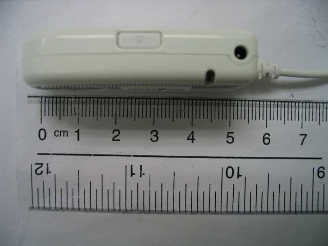
Click to zoom
Application Details
- Equipment Class
- DSS - Part 15 Spread Spectrum Transmitter
- Date of Grant
- Nov 27, 2005
- Application Purpose
- Original Equipment
- Date of Application
- Nov 27, 2005
- Equipment Note
- Bluetooth Dongle
- Frequency Range
- 2402.00000000 - 2480.00000000
- Company
- i.Tech Dynamic Limited
- Country
- Hong Kong
Documents & Files
Document Text
Text extracted from the exhibit documents filed with the FCC. Open a document above to read the original.
Users Manual
www.tuv.com Test Report No.: 14010785 001 Appendix 4 page 7 of 30 1.6 User Manual Cover Page Version 1 BlueCON35 IIe www.tuv.com Test Report No.: 14010785 001 Appendix 4 page 8 of 30 Page 0 Thank you for purchasing the i.Tech BlueCON35 IIe – Wireless Audio Dongle and welcome to join our wireless exciting world of Hi-Fi quality stereo music joyfulness. Please read this user guide carefully to ensure the better enjoyment. www.tuv.com Test Report No.: 14010785 001 Appendix 4 page 9 of 30 Table of Content i.Tech BlueCON35 II Overview .................................................................... 11 Getting Started ............................................................................................. 12 Charging your Dongle............................................................................................................13 Nominal Charging Time .........................................................................................................14 Talk & Standby Time ..............................................................................................................14 Low Battery.............................................................................................................................14 Turning your Dongle on and off ................................................................. 16 Turning On ..............................................................................................................................16 Turning Off..............................................................................................................................16 Pairing your dongle ..................................................................................... 18 Care and Maintenance................................................................................. 20 Dongle 20 Built-in Battery........................................................................................................................21 Charging..................................................................................................................................21 Safety Information ....................................................................................... 23 Troubleshooting .......................................................................................... 25 The Dongle..............................................................................................................................25 Declaration of Conformity (DOC) ............................................................... 27 Product Specifications................................................................................ 29 www.tuv.com Test Report No.: 14010785 001 Appendix 4 page 10 of 30 Page 2 www.tuv.com Test Report No.: 14010785 001 Appendix 4 page 11 of 30 i.Tech BlueCON35 IIe Overview Fig. 1 3.5mm Stereo phone plug Status indicator MFB (Multifunction Button) Charging Socket Built-In Rechargeable Battery www.tuv.com Test Report No.: 14010785 001 Appendix 4 page 12 of 30 Getting Started To use your i.Tech BlueCON35 IIe (“the Dongle”), please follow these simple steps: Charge your Dongle Pair your Dongle with any Stereo Headset has A2DP profile www.tuv.com Test Report No.: 14010785 001 Appendix 4 page 13 of 30 Page 3 Charging your Dongle Fig. 2 The dongle comes with a built-in rechargeable battery. Prior to using the dongle, it is recommendable to charge the battery fully for the first time. www.tuv.com Test Report No.: 14010785 001 Appendix 4 page 14 of 30 Charging Your Dongle Connect the charger to an AC wall outlet and the charger plug to the dongle’s charging socket (fig.2). The LED will be red while charging. IMPORTANT Charging indication will be delayed for a few seconds if the headset has not been used for a long time or the battery is drained. Nominal Charging Time Charging the battery fully is normally within 3 hours. When the battery is fully charged, the LED will turn blue and remains on for 30 minutes. Disconnect the charger from AC wall outlet and the headset. Press and hold the MFB (fig.1) for 2 seconds to turn the headset on, please refer to “Turning Your Headset On and Off” on the next page. Talk & Standby Time The fully charged battery offers up to 6 hours talk time and up to 150 hours standby time. When no calls are in progress, the headset remains turned on in standby mode. Low Battery When the dongle is on and the battery becomes low, the LED flashes red. Please recharge the battery as described above. www.tuv.com Test Report No.: 14010785 001 Appendix 4 page 15 of 30 www.tuv.com Test Report No.: 14010785 001 Appendix 4 page 16 of 30 Turning your Dongle on and off Turning On Press and hold the MFB for approximately 2 seconds until you see the LED flash Blue. NOTE Press the MFB again each time you turn on the Dongle to reactivate the pairing so that the connection between the Dongle and headset is resumed. For pairing, please refer to “Pairing Your BlueCON35 II” on page 5. Turning Off Press and hold the MFB for approximately 3 seconds until you see the LED indicator will not flash. www.tuv.com Test Report No.: 14010785 001 Appendix 4 page 17 of 30 Page 5 www.tuv.com Test Report No.: 14010785 001 Appendix 4 page 18 of 30 Pairing your dongle 1. Press the “MFB” button and hold for 8 seconds until the LED indicator flash “Blue” and “Red” alternately 2. Press and hold your bluetooth headset (A2DP profile enabled) and start the pairing mode. 3. The dongle will start pairing automatically until the LED indicator flashes “Blue” only 4. Once the pairing has been successfully completed, the LED indicator will only flash “Blue” 5. Enjoy your stereo music with the dongle Note : z If LED indicator shows “Purple” or is off, please repeat step 2 – 5 again z The default passkey of the dongle is “8888” www.tuv.com Test Report No.: 14010785 001 Appendix 4 page 19 of 30 Page 6 www.tuv.com Test Report No.: 14010785 001 Appendix 4 page 20 of 30 Care an…
Text truncated - open the document above for the full version.
External Photos
www.tuv.com Test Report No.: 14010785 001 Appendix 3 page 2 of 8 1.1 External view 1.1.1 Front view 1.1.2 Rear view www.tuv.com Test Report No.: 14010785 001 Appendix 3 page 3 of 8 1.1.3 Side view 1 1.1.4 Side view 2 www.tuv.com Test Report No.: 14010785 001 Appendix 3 page 4 of 8 1.1.5 Side view 3
ID Label/Location Info
www.tuv.com Test Report No.: 14010785 001 Appendix 4 page 2 of 30 1.1 FCCID Label Artwork The yellow oval shows the location of the Rating Label.
Internal Photos
www.tuv.com Test Report No.: 14010785 001 Appendix 3 page 5 of 8 1.2 Internal view 1.2.1 Front side 1 The yellow circle indicates the location of the antenna. www.tuv.com Test Report No.: 14010785 001 Appendix 3 page 6 of 8 1.2.2 Front side 2 1.2.3 Front side 3 www.tuv.com Test Report No.: 14010785 001 Appendix 3 page 7 of 8 1.2.4 Front side 4 www.tuv.com Test Report No.: 14010785 001 Appendix 3 page 8 of 8 1.2.5 Rear side 1.2.6 Side View
Operational Description
www.tuv.com Test Report No.: 14010785 001 Appendix 4 page 3 of 30 1.2 Operational Descriptions Transmitter Receiver Operating frequency range 2402 - 2480 MHz 2402 - 2480 MHz Type of modulation FHSS modulation FHSS modulation Number of channels 79 79 Channel separation 1 MHz 1 MHz Type of antenna Integral Antenna Integral Antenna Antenna gain (dBi) 2 2 Power level fix fix Type of equipment stand alone stand alone Connection to public utility power line No Nominal voltage V nor : 3.9 V V nor : 3.9 V Independent Operation Modes Page scan Inquiry scan Connection state - ACL Link Connection state - SCO Link 1.2.1 Product Descriptions The test item is a dongle based on the Bluetooth technology. It transfers the audio signal from the audio port to a corresponding Bluetooth Headset wirelessly. Bluetooth is a short-range radio link intended to be a cable replacement between portable and/or fixed electronic devices. 1.2.2 Technical Background of the Wireless Technology Bluetooth operates in the unlicensed ISM band at 2.4 GHz. A frequency hop transceiver is applied to combat interference and fading. A shaped, binary FM modulation is applied to minimize transceiver complexity. The symbol rate is 1 Ms/s. A slotted channel is applied with a nominal slot length of 625 μs. For full duplex transmission, a Time-Division Duplex (TDD) scheme is used. On the channel, information is exchanged through packets. Each packet is transmitted on a different hop frequency. A packet nominally covers a single slot, but can be extended to cover up to five slots. The Bluetooth protocol uses a combination of circuit and packet switching. Slots can be reserved for synchronous packets. Bluetooth can support an asynchronous data channel, up to three simultaneous synchronous voice channels, or a channel which simultaneously supports asynchronous data and synchronous voice. Each voice channel supports a 64 kb/s synchronous (voice) channel in each direction. The asynchronous channel can support maximal 723.2 kb/s asymmetric (and still up to 57.6 kb/s in the return direction), or 433.9 kb/s symmetric. The Bluetooth system consists of a radio unit, a link control unit, and a support unit for link management and host terminal interface functions.
Test Report
www.tuv.com Test Report No.: 14010785 001 Date: 23.11.2005 page 2 of 14 Table of Content Page Cover Page .................................................................................1 Table of Content ..........................................................................2 Product information.......................................................................................................4 Manufacturers declarations ....................................................................................................................... 4 Product function and intended use........................................................................................................... 4 Submitted documents ................................................................................................................................ 4 Special accessories and auxiliary equipment.......................................................................................... 4 List of Test and Measurement Instruments.................................................................5 Result FCC Part 15 – Subpart C ...................................................................................6 Subclause 15.203 – Antenna Information....................................................................... Pass................. 6 Subclause 15.204 – Antenna Information....................................................................... Pass................. 6 Subclause 15.207 – Disturbance Voltage on AC Mains ................................................ Pass................. 6 Subclause 15.247 (a) – Carrier Frequency Separation.................................................. Pass................. 7 Subclause 15.247 (a) – Time of Occupancy (Dwell Time) ............................................. Pass................. 8 Subclause 15.247 (a) – 20 dB Bandwidth ....................................................................... Pass................. 9 Subclause 15.247 (a) – Hopping Sequence .................................................................... Pass.................9 Subclause 15.247 (a) – Equal Hopping Frequency Use ................................................ Pass............... 10 Subclause 15.247 (a) – Receiver Input Bandwidth ........................................................ Pass............... 11 Subclause 15.247 (a) – Receiver Hopping Capability.................................................... Pass............... 11 Subclause 15.247 (b) – Peak Output Power ................................................................... Pass............... 11 Subclause 15.247 (b) – Band edge compliance ............................................................. Pass............... 12 Subclause 15.247 (c) – Spurious Conducted Emissions .............................................. Pass............... 12 Subclause 15.247 (c) – Spurious Radiated Emissions.................................................. Pass............... 13 i.Tech BlueCON35 IIe Overview ..................................................................................11 Getting Started .............................................................................................................12 Charging your Dongle............................................................................................................................... 13 Nominal Charging Time ............................................................................................................................ 14 Talk & Standby Time ................................................................................................................................. 14 www.tuv.com Test Report No.: 14010785 001 Date: 23.11.2005 page 3 of 14 Low Battery................................................................................................................................................ 14 Turning your Dongle on and off .................................................................................16 Turning On ................................................................................................................................................. 16 Turning Off................................................................................................................................................. 16 Pairing your dongle.....................................................................................................18 Care and Maintenance.................................................................................................20 Dongle 20 Built-in Battery........................................................................................................................................... 21 Charging..................................................................................................................................................... 21 Safety Information.......................................................................................................23 Troubleshooting ..........................................................................................................25 The Dongle................................................................................................................................................. 25 Declaration of Conformity (DOC) ...............................................................................27 Product Specifications ................................................................................................29 Appendix 1 – Test protocols 27 pages Appendix 2 – Test setup 4 pages Appendix 3 – Photo documentation 9 pages Appendix 4 – Product documentation 30 pages www.tuv.com Test Report No.: 14010785 001 Date: 23.11.2005 page 4 of 14 Product information Manufacturers declarations Transmitter Receiver Operating frequency range 2402 - 2480 MHz 2402 - 2480 MHz Type of modulation FHSS modulation FHSS modulation Number of channel…
Text truncated - open the document above for the full version.
Test Setup Photos
www.tuv.com Test Report No.: 14010785 001 Appendix 2 page 2 of 4 Set-up for Radiation Emission (Transceiver) www.tuv.com Test Report No.: 14010785 001 Appendix 2 page 3 of 4 Set-up for Radiation Emission (Transceiver) www.tuv.com Test Report No.: 14010785 001 Appendix 2 page 4 of 4 Set-up for Radiation Emission (Transceiver)
Contact Information
Applicant
Raymond Liu(General Manager)
Technical Contact
T�V Rheinland Hong Kong Ltd.Fred Wai
[email protected]+852-2192-1000
Unit 8, 25/F., Skyline Tower · Hong Kong · Hong Kong
Test Firm
Hong Kong Productivity CouncilIr Angel Wong Yuen-yee
Technical Specifications
| # | Rule Parts | Frequency Range | Power Output |
|---|---|---|---|
| 1 | 15C | 2.40 GHz - 2.48 GHz | 2.51 mW |
Other Applications from i.Tech Dynamic Limited
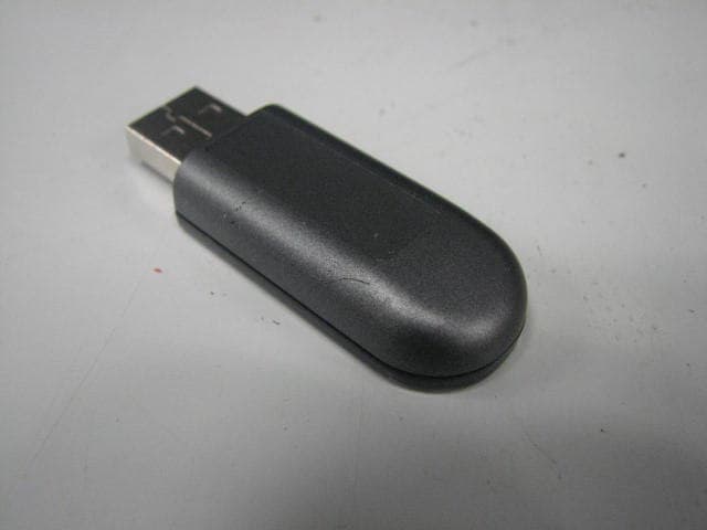
RKIC51-B115-XX
Oct 28, 2010Bluetooth Dongle
Equipment Class
DSS - Part 15 Spread Spectrum Transmitter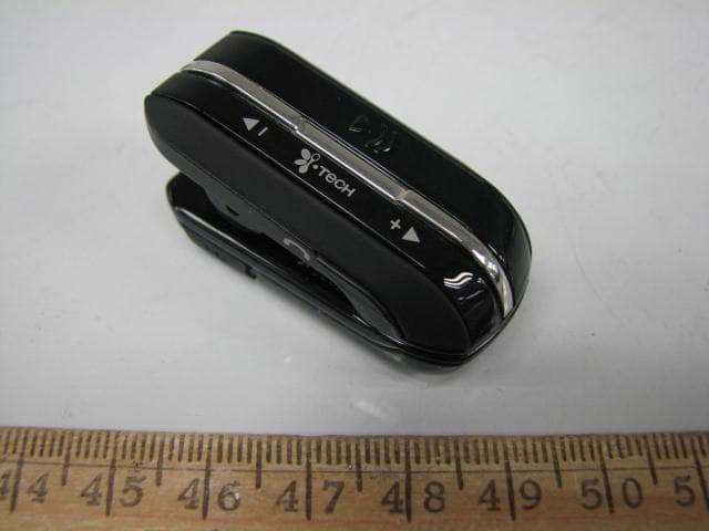
RKIC51-B806-XX
Aug 29, 2010Bluetooth Headset
Equipment Class
DSS - Part 15 Spread Spectrum Transmitter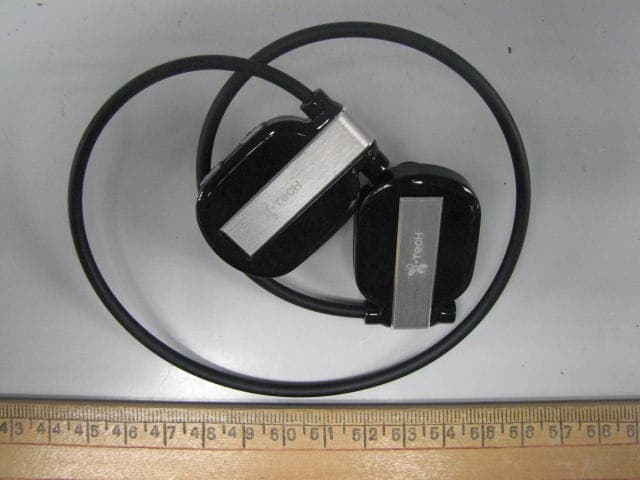
RKIC51-B807-XX
Jun 29, 2010Bluetooth Headset
Equipment Class
DSS - Part 15 Spread Spectrum Transmitter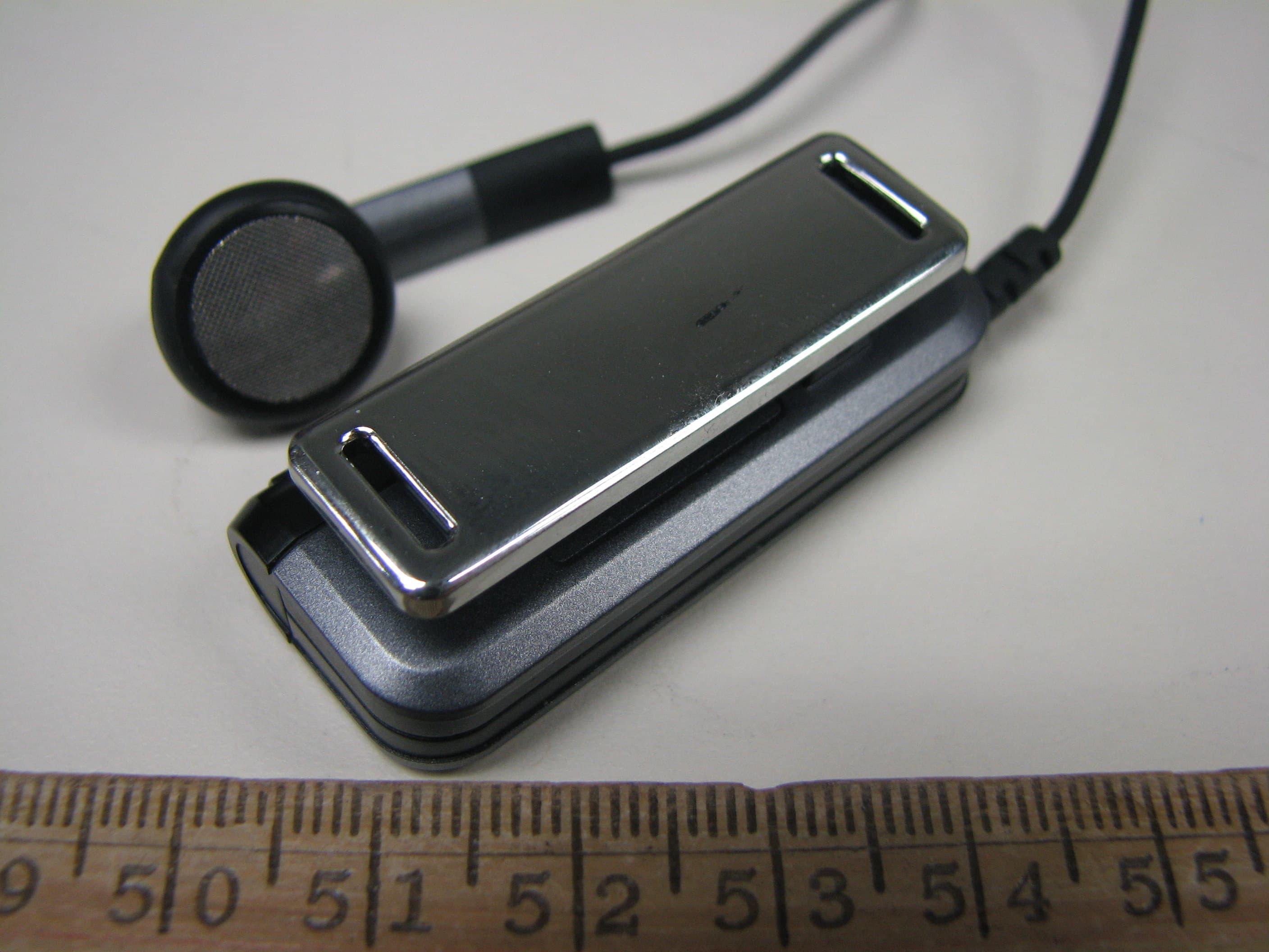
RKIC51-B604-XX
May 16, 2010Bluetooth Headset
Equipment Class
DSS - Part 15 Spread Spectrum Transmitter
RKIC51-B606-XX
Apr 07, 2010Bluetooth Headset
Equipment Class
DSS - Part 15 Spread Spectrum Transmitter