RKIC51-A05054-XXBluetooth Headset
i.Tech Dynamic Limited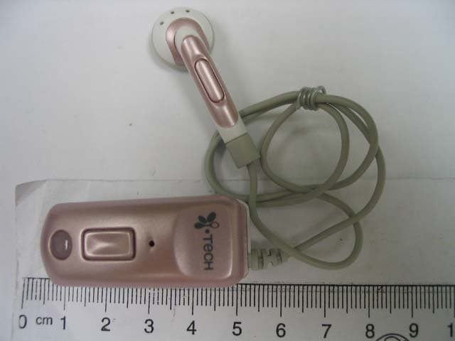
Click to zoom
Application Details
- Equipment Class
- DSS - Part 15 Spread Spectrum Transmitter
- Date of Grant
- May 21, 2006
- Application Purpose
- Original Equipment
- Date of Application
- May 21, 2006
- Equipment Note
- Bluetooth Headset
- Frequency Range
- 2402.00000000 - 2480.00000000
- Company
- i.Tech Dynamic Limited
- Country
- Hong Kong
Documents & Files
Document Text
Text extracted from the exhibit documents filed with the FCC. Open a document above to read the original.
Users Manual
2 13 2 13 15 Getting Started To use your i.Tech Clip V (“the headset”), please follow these simple steps: Charge your headset Pair your headset with a Bluetooth-enabled mobile handset 12 3 12 12 3 (fig.1) Charger (fig.2) Charging Socket Charger Plug Charging Your Headset 4 11 4 11 Bluetooth Specification: Version 1.2 Class 2 Bluetooth Profile Supported: Headset and Handsfree Range of Frequency: 2.4GHz Spectrum Talk Time*: up to 6 hours Standby Time* : up to 120 hours Nominal Charging Time: Within 3 hours Dimensions: 46(L)x18(W)x22.5(H) mm Weight: 16.7 grams Product Specifications Charging Your Headset Connect the charger to an AC wall outlet (mains socket) and the charger plug to the headset’s charging socket (fig.1). The LED will be red while charging. IMPORTANT Charging indication will be delayed for a few seconds if the headset has not been used for a long time or the battery is drained. Charging Time Charging the battery fully is normally within 3 hours. When the battery is fully charged, the LED will turn blue and remain on. Disconnect the charger from AC wall outlet (mains socket) and the headset. Press and hold the MFB (fig.1) for 2 seconds to turn the headset on, please refer to “Turning Your Headset On and Off” . Talk & Standby Time The fully charged battery offers up to 6 hours talk time and up to 120 hours standby time. When no calls are in progress, the headset remains turned on in standby mode. Low Battery When the headset is on and the battery becomes low, the status indicator flashes red and the headset emits a beep every 1 minute. Please recharge the battery as described above. 10 5 10 5 Adjusting the Volume Press the volume key repeatedly until you reach the desired volume level. The listening volume may be affected by the volume setting of the caller’s handset as well. Re-adjust the listening volume again when necessary. Resetting or Removing Pairing You may reset the headset to its original settings anytime. To do this you also clear all current pairing settings. 1. Ensure the headset is off. 2. Press and hold the volume key for 20 seconds until LED flashes Red and Blue alternatively. 3. Release the volume key. 4. Press and hold the volume key again until you hear two beeps. 5. Recharge the headset for a few seconds. The headset is then turned off and returned to its original settings. All previous pairing settings are cleared. Rejecting a Call (Handsfree Profile ONLY) Press and hold the volume key then press and hold the MFB until the incoming call is rejected. Transferring a Call (Handsfree Profile ONLY) Press and hold the volume then press and hold the MFB until the audio is transferred from headset to your mobile handset during conversation. Turning On the Headset Press and hold the MFB for two seconds until you hear a short beep. The status indicator will then flash blue. IMPORTANT: Press the MFB again each time when you want to turn on the headset to re-activate pairing so as to resume the connection between the headset and the mobile handset. For pairing, please refer to the “Pairing Your Headset” section for details. Turning Off the Headset Press and hold the MFB for approximately 3 seconds until you hear a long beep. The status indicator will stop flashing. IMPORTANT To disconnect the Bluetooth connection, press the MFB firmly to turn off your headset. If you will not be using the headset for a while, you should consider turning off the Bluetooth function on your mobile phone as well. Turning Your Headset On and Off 6 9 6 9 Pairing Your Headset Voice Dialling from Your Headset If your mobile handset is equipped with a voice dialling function, simply press the MFB on your headset, and when you hear a beep say the voice tag. IMPORTANT For voice dialling, you must record the voice tag (the person’s name) into your mobile handset first before using the voice dialling function. Please refer to your mobile handset’s user guide on how to record the voice tags . Last Number Redialling from Your Headset Short press the MFB on your headset twice. IMPORTANT The above functions are only applicable to mobile handsets with Bluetooth Handsfree Profile. Functionality varies depending on the mobile handset model you have. Please refer to your mobile handset user guide for additional information. Using Your Headset 8 7 8 7 1. Place the headset and the mobile handset no more then 1 meter apart and ensure there is nothing in between. 2. Ensure the headset is OFF. 3. Press and hold the MFB approximately 8 seconds until the headset status indicator alternately flashes blue and red. 4. Activate your mobile handset’s Bluetooth function by referring to your mobile handset user guide for details. 5. Set the mobile handset to search for Bluetooth devices within 1 meter range as instructed in the mobile handset user guide and select “i.Tech Clip V” from the list. 6. Enter the preprogrammed passkey “0000” and press “OK” to pair your headset and mobile handset. When the pairing is complete, the headset status indicator will flash blue rapidly 5 times followed by a long beep. 7. Press “Return” to go back to your mobile handset’s main menu. For certain mobile handset models, a headset icon will be shown on the screen. You should now be able to make and receive calls using your headset. IMPORTANT If the pairing cannot be completed within 2 minutes while the pairing mode is activated, the headset status indicator flashes purple followed by 3 beeps and the headset is turned off. Please repeat the above pairing procedures. Pairing Your Headset Using Your Headset Answering a Call When there is an incoming call, you will hear ringing through the earphone and the built-in buzzer. Press the MFB to accept the call or answer the call via your mobile handset in the normal way. IMPORTANT You can stop the buzzer alert by pressing the volume key once. The buzzer will ring again when there is another incoming call. Ending a Call Press the MFB to end your call or end the call via your mobile handset in the …
Text truncated - open the document above for the full version.
External Photos
www.tuv.com Test Report No.: 14010927 001 Appendix 3 page 1 of 8 Appendix 3 Construction Photos www.tuv.com Test Report No.: 14010927 001 Appendix 3 page 2 of 8 1.1 External view 1.1.1 Front view 1.1.2 Rear view www.tuv.com Test Report No.: 14010927 001 Appendix 3 page 3 of 8 1.1.3 Side view 1 1.1.4 Side view 2 www.tuv.com Test Report No.: 14010927 001 Appendix 3 page 4 of 8 1.1.5 Side view 3
ID Label/Location Info
www.tuv.com Test Report No.: 14010927 001 Appendix 4 page 1 of 31 Appendix 4 Technical Documents www.tuv.com Test Report No.: 14010927 001 Appendix 4 page 2 of 31 1.1 FCCID Label Artwork The yellow oval shows the location of the Rating Label.
Internal Photos
www.tuv.com Test Report No.: 14010927 001 Appendix 3 page 5 of 8 1.2 Internal view 1.2.1 Front side 1 The yellow circle indicates the location of the antenna. www.tuv.com Test Report No.: 14010927 001 Appendix 3 page 6 of 8 1.2.2 Front side 2 1.2.3 Front side 3 www.tuv.com Test Report No.: 14010927 001 Appendix 3 page 7 of 8 1.2.4 Rear side 1 1.2.5 Adaptor www.tuv.com Test Report No.: 14010927 001 Appendix 3 page 8 of 8 1.2.6 Adaptor
Test Report
www.tuv.com Test Report No.: 14010927 001 Date: 20.04.2006 page 2 of 12 Table of Content Page Cover Page .................................................................................1 Table of Content ..........................................................................2 Product information.......................................................................................................3 Manufacturers declarations ....................................................................................................................... 3 Product function and intended use........................................................................................................... 3 Submitted documents ................................................................................................................................ 3 Special accessories and auxiliary equipment..............................................Error! Bookmark not defined. List of Test and Measurement Instruments.................................................................4 Result FCC Part 15 – Subpart C ...................................................................................5 Subclause 15.203 – Antenna Information....................................................................... Pass................. 5 Subclause 15.204 – Antenna Information....................................................................... Pass................. 5 Subclause 15.207 – Disturbance Voltage on AC Mains ................................................. N.A.................. 5 Subclause 15.247 (a) – Carrier Frequency Separation.................................................. Pass................. 5 Subclause 15.247 (a) – Time of Occupancy (Dwell Time) ............................................. Pass................. 6 Subclause 15.247 (a) – 20 dB Bandwidth .............................................................................. .................. 7 Subclause 15.247 (a) – Hopping Sequence .................................................................... Pass.................7 Subclause 15.247 (a) – Equal Hopping Frequency Use ................................................ Pass................. 8 Subclause 15.247 (a) – Receiver Input Bandwidth ........................................................ Pass................. 9 Subclause 15.247 (a) – Receiver Hopping Capability.................................................... Pass................. 9 Subclause 15.247 (b) – Peak Output Power ................................................................... Pass.................9 Subclause 15.247 (b) – Band edge compliance ............................................................. Pass............... 10 Subclause 15.247 (c) – Spurious Conducted Emissions .............................................. Pass............... 10 Subclause 15.247 (c) – Spurious Radiated Emissions.................................................. Pass............... 11 Appendix 1 – Test protocols 24 pages Appendix 2 – Test setup 2 pages Appendix 3 – Photo documentation 7 pages Appendix 4 – Product documentation 31 pages www.tuv.com Test Report No.: 14010927 001 Date: 20.04.2006 page 3 of 12 Product information Manufacturers declarations Transceiver Operating frequency range 2402 - 2480 MHz Type of modulation FHSS modulation Number of channels 79 Channel separation 1 MHz Type of antenna Integral Antenna Antenna gain (dBi) 1.2 Power level fix Type of equipment stand alone, plug-in radio device Connection to public utility power line No Nominal voltage V nor : 3.7 V Independent Operation Modes Page scan Inquiry scan Connection state - ACL Link Connection state - SCO Link Product function and intended use The test item is a Bluetooth Headset based on the Bluetooth technology. Bluetooth is a short-range radio link intended to be a cable replacement between portable and/or fixed electronic devices. Bluetooth operates in the unlicensed ISM Band at 2.4 GHz. In the US a band of 83.5 MHz width is available. In this band, 79 RF channels spaced 1 MHz apart are defined. The channel is represented by a pseudo-random hopping sequence through the 79 channels. The channel is divided into time slots, with a nominal slot length of 625 μs, where each slot corresponds to different RF hop frequencies. The nominal hop rate is 1600 hops/s. The symbol rate on the channel is 1 Ms/s. Submitted documents Circuit Diagram Block Diagram Bill of material User manual www.tuv.com Test Report No.: 14010927 001 Date: 20.04.2006 page 4 of 12 List of Test and Measurement Instruments Kind of Equipment Manufacturer Type S/N Test Receiver Rohde & SchwarzESH-3 890173/033 L/I/S/N Rohde & SchwarzESH 3-Z5 849876/026 Oscilloscope HP 54713B US34510455 Test Receiver Rohde & SchwarzESVP 882402/033 Absorbing Clamp Rohde & SchwarzMDS-21 979 3/4 Test Receiver Rohde & SchwarzESVS30 842807/009 Biconical Antenna Rohde & SchwarzHK116 841489/015 Log.-Periodic Antenna Rohde & SchwarzHL223 841516/017 Universal Power Analyzer Voltech PM3000A 9915 Reference Impedance Network Voltech IEC 555 Standard 9946 AC Power Source California Instr. 4500L HK51895 Trip-Loop Antenna Chase LLA6142 1019 Double Ridge Horn Antenna EMCO 3115 9002-3351 Double Ridge Horn Antenna EMCO 3115 9002-3347 RF Comms Test Set HP 8920B US36492628 Spectrum Analyser + Tracking G. HP 8596E 3639A00758 Signal Generator Rohde & SchwarzSMY 01 844146/024 Signal Generator Rohde & SchwarzSMY 01 844146/023 BiLog Antenna EMCO 3143 9607-1287 Isotropic Field Probe Holladay HI-4422 90956 Power Amplifier Kalmus 757-LC 7620-1 Power Amplifier Kalmus 122-FC 7620-2 Coupling Clamp Schaffner CDN 126 312 Couple Device Network Fischer CDN-M2 9604 Spectrum Analyzer Rohde & SchwarzFSP30 1093.4495K30 Temperature Chamber Binder MK 240 9020-0028 EFT,ESD,SURGE, DIPS tester Schaffner Best 96 IN3796-011 Surge Generator Schaffner NSG650 280 Active Loop Antenna EMCO 6502 9107-2651 www.tuv.com Test Report No.: 14010927 001 Date: 20.04.2006 page 5…
Text truncated - open the document above for the full version.
Test Setup Photos
www.tuv.com Test Report No.: 14010927 001 Appendix 2 page 1 of 2 Appendix 2 Test Setup Photos www.tuv.com Test Report No.: 14010927 001 Appendix 2 page 2 of 2 Set-up for Radiation Emission (Transceiver)
Contact Information
Applicant
Raymond Liu(General Manager)
Technical Contact
T�V Rheinland Hong Kong LtdSharon Li
[email protected]+852 2192 1000
Unit 8, 25/F., Skyline Tower · Hong Kong · Hong Kong
Test Firm
Hong Kong Productivity CouncilIr Angel Wong Yuen-yee
Technical Specifications
| # | Rule Parts | Frequency Range | Power Output |
|---|---|---|---|
| 1 | 15C | 2.40 GHz - 2.48 GHz | 2.58 mW |
Other Applications from i.Tech Dynamic Limited
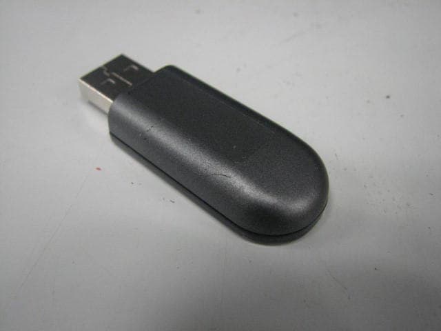
RKIC51-B115-XX
Oct 28, 2010Bluetooth Dongle
Equipment Class
DSS - Part 15 Spread Spectrum Transmitter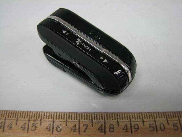
RKIC51-B806-XX
Aug 29, 2010Bluetooth Headset
Equipment Class
DSS - Part 15 Spread Spectrum Transmitter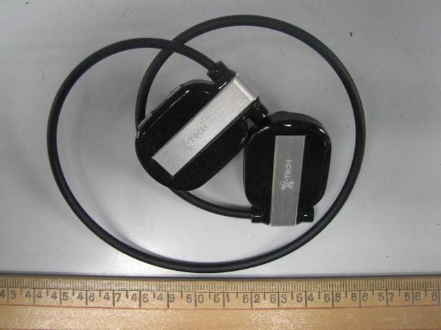
RKIC51-B807-XX
Jun 29, 2010Bluetooth Headset
Equipment Class
DSS - Part 15 Spread Spectrum Transmitter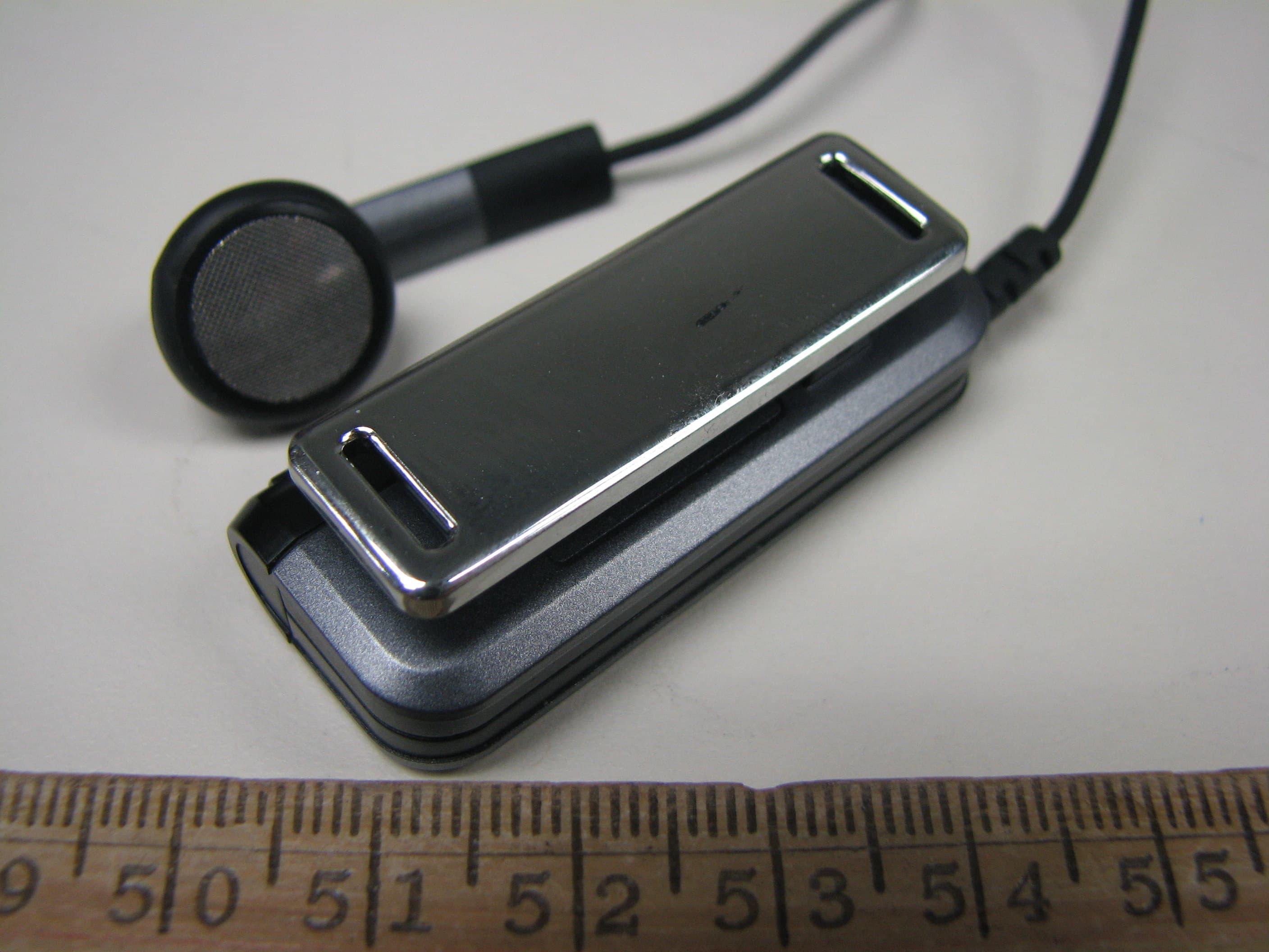
RKIC51-B604-XX
May 16, 2010Bluetooth Headset
Equipment Class
DSS - Part 15 Spread Spectrum Transmitter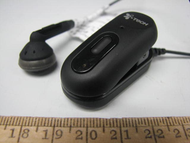
RKIC51-B606-XX
Apr 07, 2010Bluetooth Headset
Equipment Class
DSS - Part 15 Spread Spectrum Transmitter