RL3ALTE100070 GHz Transceiver
Comotech Corporation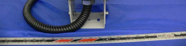
Click to zoom
Application Details
- Equipment Class
- TNB - Licensed Non-Broadcast Station Transmitter
- Date of Grant
- Jan 29, 2006
- Application Purpose
- Original Equipment
- Date of Application
- Jan 29, 2006
- Equipment Note
- 70 GHz Transceiver
- Frequency Range
- 71500.00000000 - 74900.00000000
- Company
- Comotech Corporation
- Country
- South Korea
Documents & Files
Document Text
Text extracted from the exhibit documents filed with the FCC. Open a document above to read the original.
Users Manual
Installation and Service Manual Millimeter-wave Radio Communication System 60 Series - ME100 / ME1000 70 Series - TE100 / TE1000 COMOTECH CORPORATION TM 60 Series – ME100 / ME1000 70 Series – TE100 / TE1000 TM Copyright ©2004 Comotech Corp. All Rights Reserved. Comotech Corp. has an exclusive right to the information included in this document, and this matter is protected by the related copyright, patent, and intellectual property right. The products and software stated in this document can’t be translated into another language by arbitrary forms or ways without the written consent of Comotech Corp. and can’t be kept, photocopied, delivered, or reorganized into storage media. Comotech products are explained in this document to simply provide the information. It doesn’t guarantee the matters indicate or include the future performance improvement. The Comotech product design and performance can be changed without prior notice or consent. The registered unique marks and trademark rights such as the products and company names indicated in this document are owned by individual companies and used for verification or explanation not to damage the owner’s profit. 1. Introduction 1-1. AirLight™ Family .................................................... 1-1 1-2. Advantages of AirLight™ Series .................................................... 1-1 1-3. AirLight™ Features .................................................... 1-2 1-4. AirLight™ Application .................................................... 1-3 2. Description 2-1. General Equipment .................................................... 2-1 3. Deployment 3-1. Pre-Installation Notice .................................................... 3-1 3-2. Installed-Location Notice .................................................... 3-2 3-3. Safety and Notice .................................................... 3-3 3-4. Tools and Equipments .................................................... 3-5 3-5. How to Connect AirLight™ .................................................... 3-6 3-6. Cabling Check .................................................... 3-12 4. AirLight™ Monitoring Program(ALMP) 4-1. Introduction .................................................... 4-1 4-2. Installation .................................................... 4-2 4-3. Getting Start .................................................... 4-3 5. Troubleshooting 5-1. General ALMP Features .................................................... 5-1 5-2. Problem Solving .................................................... 5-1 6. Specification 6-1. AirLight 60 Series Specification .................................................... 6-1 6-2. AirLight 70 Series Specification .................................................... 6-2 7. Terminal Location .................................................... 7-1 8. Warranty .................................................... 8-1 ★ Table of Contents ★ 1 - 1 Introduction 1. Introduction 1-1. AirLight™ Family AirLight™ applies the original Comotech technology to millimeter-wave and provides the system doing the wireless transmission of various types of digital signals from 100 Mbps to 1.25Gbps. Especially, Fast Ethernet (125 Mbps) and Gigabit Ethernet (1.25Gbps) are provided with standards, and product flexibility is provided to determine the desired standards depending on user requirements. 1-2. Advantages of AirLight™ Series √ High Tech – Application of original Comotech technology has further enhanced the reliability of millimeter wave band products. √ Unlicensed Frequency Band – There are many countries that generally don’t need license and declare to use the frequency in case of 60 series. √ High Data Transmission Speed – The systems with various speeds from 100 Mbps to 1.25Gbps can be serviced and supported. √ High Security and Frequency Reuse – Good security is guaranteed by high directivity, and the reuse of frequency in the unit of pico cell is possible due to the frequency characteristics of the millimeter wave. Figure 1-1 AirLight™ ODU (Out Door Unit) Introduction - 60 / 70 Series 1 - 2 COMOTECH CORPORATION 1-3. AirLight™ Features AirLight™ has the following features. ▶ Next Generation Communication Technology √ Integration of high tech √ Digital direct conversion √ Good security √ Data acceptance capability with high capacity √ Low power consumption ▶ Wireless and Fiber Distributed Network Configuration √ Use of the unlicensed frequency in the 60GHz band – ME100 / ME1000 √ Possible to connect to the system using binary digital signals √ Support of the maximum 1.25Gbps (Gigabit Ethernet) speed from 100 Mbps √ Support of various interfaces: FDDI, UTP, etc. √ Possible to design in compliance with the communication regulation of each country ( FCC, TELEC, ITU-R) ▶ Low Cost and High Efficiency √ Possible to configure very high speed network with the low cost √ Low maintenance and repair cost without laying √ Possible to install and operate with the small number of persons (1 or 2 persons) √ Possible to send the data with high capacity and flexibly connect to another system √ Possible to connect to IP network √ The same transmission efficiency as the wired one 1 - 3 Introduction ▶ Efficient Network Management √ Provision of the efficient network management program (IDU) √ Support of the RS-485 communication port to check the AirLight™ state √ The management function by ALMP, AirLight™ Monitoring Program 1-4. AirLight™ Application AirLight™ is a ultra high speed wireless LAN communication product. Configuring the wireless network with P2P, P2M, or M2P types among large buildings makes it possible to communicate the data with the adjacent system through the wireless network. This configuration can replace the area difficult to lay the optical cables and communication facilities requiring high security. The wired and wireless double security management system, Using both network among banks in the neighborhood, and the regional admin…
Text truncated - open the document above for the full version.
Cover Letter(s)
February 3, 2006 Federal Communications Commission Authorization and Evaluation Division 7435 Oakland Mills Rd. Columbia, MD 21046 Reference FCC ID: RL3ALTE1000 Request under 47 CFR 0.457 and 0.459 that materials submitted to the commission be withheld from public inspection. ComoTech Corp. hereby requests that the materials attached here to be withheld from public inspection in accordance with 47 CFR 47 0.457 and 0.459. Specifically, ComoTech Corp. request that the internal photos, schematics, and designs to be withheld from public inspection because they are considered confidential trade secrets and technical data which customarily would be guarded from competitors: -Detailed circuit schematics -Blog Diagram -Internal Photos Therefore, in accordance with CFR 47 0.457 and 0.459, ComoTech Corp. requests that the above listed material, copies of which are here, to be withheld from public inspection. Authorized signature: Sincerely, Tae Ho Lee/Director ComoTech Corporation 1-908, Ulsan APT-Bldg., 812-1, Hyomun-Dong, Buk-Gu, Ulsan City, 683-360, Korea 82-52-288-7550
External Photos
Comotech Corporation FCC ID: RL3- ALTE1000 Report # R0512154Exhibits.doc Page 3 of 38 FCC Part 22, 24 Type Approvals Report EXHIBIT C - EUT PHOTOGRAPHS EUT - Front View EUT - Rear View
ID Label/Location Info
EXHIBIT A - FCC ID LABELING AND WARNING STATEMENT Proposed FCC ID Label Specifications : Text is black or white in color and is left justified. Labels are silk-screened and shall be “permanently affixed” at a conspicuous location on the EUT. Proposed Label Location on EUT Bottom View of the EUT/Proposed ID Label Location FCC Warning Statement A FCC Warning Statement is provided in the product manual. FCC ID: RL3- ALTE1000
ID Label/Location Info
Comotech Corporation FCC ID: RL3- ALTE1000 Report # R0512154 Page 20 of 30 FCC Part 101 Type Approvals Report EXHIBIT A - FCC ID LABELING AND WARNING STATEMENT Proposed FCC ID Label and warning statement Specifications : Text is black or white in color, left justified, in a font size large enough to be legible without the aid of magnification. Labels shall be “permanently affixed” or silk screened upon the antenna location on the EUT. Proposed Label Location on EUT Back View of the EUT: Proposed ID/Label Location: FCC Warning Statement As per FCC 1.1307 (b) A FCC Warning Statement must be permanently affixed to the antenna portion of the product and provided in the product manual that: (1) provides adequate notice regarding potential radiofrequency safety hazards, e.g., information regarding the safe minimum separation distance required between users and transceiver antennas; (2) references the applicable FCC-adopted limits for radiofrequency exposure specified in § 1.1310. FCC ID: RL3- ALTE1000 Warning: this device is a high powered transceiver that operates at frequencies that could be potentially harmful to human tissue if the following precautions are not taken, (1) Minimum safe operating distance of 1.2 meters must be observed at all times between unit and users* (2) Unit shall be mounted so that minimum operating distance is not inadvertently impinged by the general public, or non user personnel. *Please see ex posure limits listed in FCC §1.1310
ID Label/Location Info
Comotech Corporation FCC ID: RL3- ALTE1000 Report # R0512154 Page 20 of 30 FCC Part 101 Type Approvals Report EXHIBIT A - FCC ID LABELING AND WARNING STATEMENT Proposed FCC ID Label and warning statement Specifications : Text is black or white in color, left justified, in a font size large enough to be legible without the aid of magnification. Labels shall be “permanently affixed” or silk screened upon the antenna location on the EUT. Proposed Label Location on EUT Back View of the EUT: Proposed ID/Label Location: FCC Warning Statement As per FCC 1.1307 (b) A FCC Warning Statement must be permanently affixed to the antenna portion of the product and provided in the product manual that: (1) provides adequate notice regarding potential radiofrequency safety hazards, e.g., information regarding the safe minimum separation distance required between users and transceiver antennas; (2) references the applicable FCC-adopted limits for radiofrequency exposure specified in § 1.1310. FCC ID: RL3- ALTE1000 Warning: this device is a high powered transceiver that operates at frequencies that could be potentially harmful to human tissue if the following precautions are not taken, (1) Minimum safe operating distance of 1.2 meters must be observed at all times between unit and users* (2) Unit shall be mounted so that minimum operating distance is not inadvertently impinged by the general public, or non user personnel. *Please see ex posure limits listed in FCC §1.1310
RF Exposure Info
§1.1307(b)(1), §2.1091 & 101.1525 - RF EXPOSURE According to §1.1310 and §2.1091 RF exposure is calculated. Limits for General Population/Uncontrolled Exposure Frequency Range (MHz) Electric Field Strength (V/m) Magnetic Field Strength (A/m) Power Density (mW/cm 2 ) Averaging Time (minute) Limits for General Population/Uncontrolled Exposure 0.3-1.34 614 1.63 *(100) 30 1.34-30 824/f 2.19/f *(180/f 2 ) 30 30-300 27.5 0.073 0.2 30 300-1500 / / f/1500 30 1500-100,000 / / 1.0 30 f = frequency in MHz * = Plane-wave equivalent power density MPE Prediction Predication of MPE limit at a given distance Equation from page 18 of OET Bulletin 65, Edition 97-01 S = PG/4πR² Where: S = power density P = power input to antenna G = power gain of the antenna in the direction of interest relative to an isotropic radiator R = distance to the center of radiation of the antenna 71.5 Ghz Transmitter Maximum peak output power at antenna input terminal: 9 (dBm ) Maximum peak output power at antenna input terminal: 7.9(mW) Prediction distance: 120 (cm) Predication frequency: 71500 (MHz) Antenna Gain (typical): 43 (dBi) antenna gain: 19952.6 (numeric) Power density at predication frequency at 120 cm: 0.871 (mW/cm 2 ) MPE limit for uncontrolled exposure at prediction frequency: 1 (mW/cm 2 ) 74.9 Ghz Transmitter Maximum peak output power at antenna input terminal: 8.8 (dBm ) Maximum peak output power at antenna input terminal: 7.59 (mW) Prediction distance: 120 (cm) Predication frequency: 74900 (MHz) Antenna Gain (typical): 43 (dBi) antenna gain: 19952.6 (numeric) Power density at predication frequency at 20 cm: 0.837 (mW/cm 2 ) MPE limit for uncontrolled exposure at prediction frequency: 1 (mW/cm 2 ) Test Result The EUT is a mobile device. The power density level at 120 cm is 0.871 mW/cm² and 0.837 mW/ cm², which is below the uncontrolled exposure limit of 1 mW/cm².
Test Report
Note: This test report is specially limited to the above client company and this particular sample only. It may not be duplicated without prior written consent of Bay Area Compliance Laboratory Corporation. This report must not be used by the client to claim product certification, approval, or endorsement by NVLAP, NIST or any agency of the U.S. Government. FCC PART 101 TYPE APPROVALS EMI MEASUREMENT AND TEST REPORT For ComoTech Corporation 1-908, Ulsan APT-Bldg., 812-1, Hyomun-Dong, Buk-Gu, Ulsan City, 683-360 Korea FCC ID: RL3- ALTE1000 This Report Concerns: Original Report Equipment Type: Millimeter wave radio communication system Test Engineer: Snell Leong Report No.: R0512154 Report Date: 2006-1-26 Reviewed By: James Ma Prepared By: Bay Area Compliance Laboratory Corporation (BACL) 230 Commercial Street Sunnyvale, CA 94085 Tel: (408) 732-9162 Fax: (408) 732 9164 Comotech Corporation FCC ID: RL3- ALTE1000 Report # R0512154Rpt.doc Page 2 of 17 FCC Part 101 Type Approvals Report TABLE OF CONTENTS GENERAL INFORMATION.......................................................................................................................................3 PRODUCT DESCRIPTION FOR EQUIPMENT UNDER TEST (EUT) ....................................................................................3 OBJECTIVE...................................................................................................................................................................3 RELATED SUBMITTAL(S)/GRANT(S).............................................................................................................................3 TEST METHODOLOGY..................................................................................................................................................3 TEST FACILITY.............................................................................................................................................................3 SYSTEM TEST CONFIGURATION ..........................................................................................................................5 JUSTIFICATION.............................................................................................................................................................5 BLOCK DIAGRAM.........................................................................................................................................................5 EQUIPMENT MODIFICATIONS.......................................................................................................................................5 SUMMARY OF TEST RESULTS ...............................................................................................................................6 §2.1047 §101.141 - MODULATION CHARACTERISTIC ......................................................................................7 APPLICABLE STANDARD..............................................................................................................................................7 §2.1053 / §101.111- HARMONIC & SPURIOUS EMISSIONS ................................................................................8 APPLICABLE STANDARD..............................................................................................................................................8 TEST PROCEDURE........................................................................................................................................................8 TEST EQUIPMENT LIST AND DETAILS...........................................................................................................................8 ENVIRONMENTAL CONDITIONS....................................................................................................................................8 TEST RESULT...............................................................................................................................................................9 §2.1046, §101.113 – TRANSMITTER POWER LIMITATION.............................................................................11 APPLICABLE STANDARD............................................................................................................................................11 TEST PROCEDURE......................................................................................................................................................11 TEST EQUIPMENT LIST AND DETAILS.........................................................................................................................12 ENVIRONMENTAL CONDITIONS..................................................................................................................................12 TEST RESULTS...........................................................................................................................................................12 §2.1049 & §101.109- OCCUPIED BANDWIDTH ...................................................................................................13 APPLICABLE STANDARD............................................................................................................................................13 TEST PROCEDURE......................................................................................................................................................13 TEST EQUIPMENT LIST AND DETAILS.........................................................................................................................14 ENVIRONMENTAL CONDITIONS..................................................................................................................................14 TEST RESULTS...........................................................................................................................................................14 §2.1055 (A), §2.1055 (D), §101.107- FREQUENCY STABILITY ................................…
Text truncated - open the document above for the full version.
Test Setup Photos
Comotech Corporation FCC ID: RL3- ALTE1000 Report # R0512154Exhibits.doc Page 2 of 38 FCC Part 22, 24 Type Approvals Report EXHIBIT B - TEST SETUP PHOTOGRAPHS Radiated Emission - Front View
Contact Information
Applicant
InJun Park(General Manager)
Test Firm
Bay Area Compliance LaboratoryJohn Chan
Technical Specifications
| # | Rule Parts | Frequency Range | Power Output | Emission | Tolerance |
|---|---|---|---|---|---|
| 1 | 101 | 71.50 GHz - 74.90 GHz | 7.90 mW | 285KK1D | 0.0200000000 % |
Other Applications from Comotech Corporation
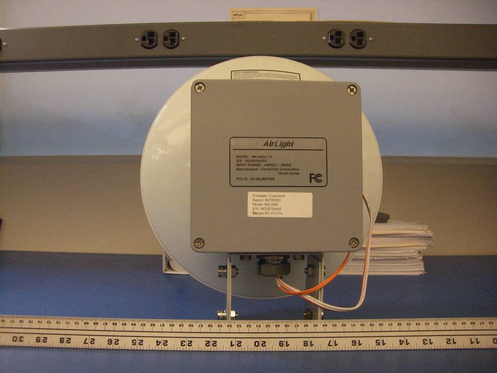
RL3ALME1000
Oct 24, 200760 GHz Transceiver
Equipment Class
DXX - Part 15 Low Power Communication Device Transmitter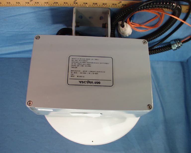
RL3ALME100
Dec 21, 200360GHz Transceiver
Equipment Class
DXX - Part 15 Low Power Communication Device Transmitter