RLY-WLM01802.11B/G/N MODULE
ADATA Technology Co. Ltd.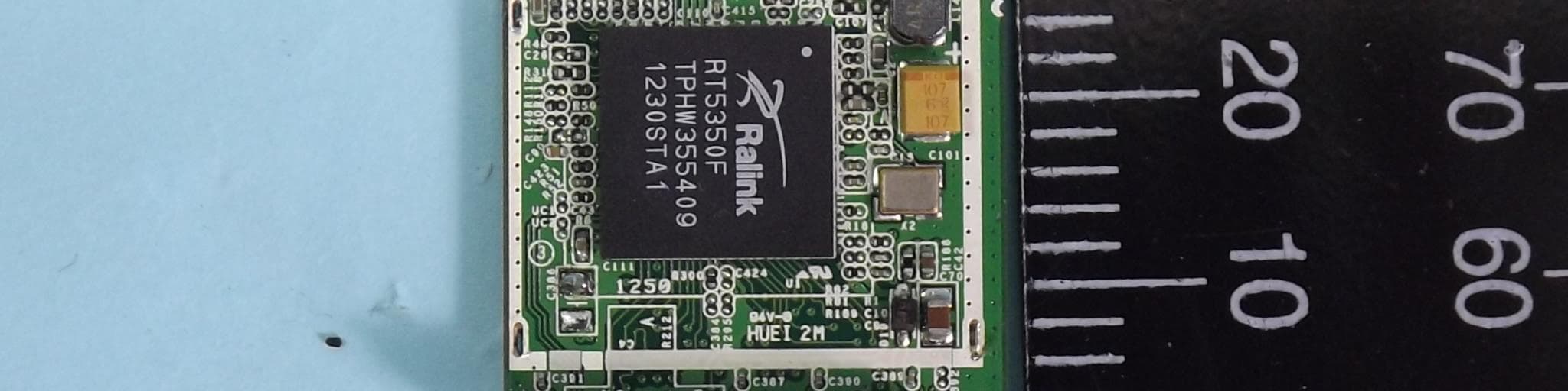
Click to zoom
Application Details
- Equipment Class
- DTS - Digital Transmission System
- Date of Grant
- Feb 05, 2013
- Application Purpose
- Original Equipment
- Date of Application
- Feb 03, 2013
- Equipment Note
- 802.11B/G/N MODULE
- Frequency Range
- 2422.00000000 - 2452.00000000
- Company
- ADATA Technology Co. Ltd.
- Country
- Taiwan
Documents & Files
Document Text
Text extracted from the exhibit documents filed with the FCC. Open a document above to read the original.
Users Manual
Integration Instruction General: This modular approval is limited to OEM/Integrators installation only. OEM integrators are responsible for ensuring that the end-user has no manual instructions to remove or install module. FCC Regulations: To integrate this module into the host, the host manufacturer is responsible for the applicable FCC rules, including the limits for a Class B digital device, pursuant to Part 15 of the FCC Rules In the user manual of the host device, the following statements are required to be included. This device complies with part 15 of the FCC Rules. Operation is subject to the following two conditions: (1) This device may not cause harmful interference, and (2) this device must accept any interference received, including interference that may cause undesired operation. This device has been tested and found to comply with the limits for a Class B digital device, pursuant to Part 15 of the FCC Rules. These limits are designed to provide reasonable protection against harmful interference in a residential installation. This equipment generates, uses and can radiated radio frequency energy and, if not installed and used in accordance with the instructions, may cause harmful interference to radio communications. However, there is no guarantee that interference will not occur in a particular installation If this equipment does cause harmful interference to radio or television reception, which can be determined by turning the equipment off and on, the user is encouraged to try to correct the interference by one or more of the following measures: -Reorient or relocate the receiving antenna. -Increase the separation between the equipment and receiver. -Connect the equipment into an outlet on a circuit different from that to which the receiver is connected. -Consult the dealer or an experienced radio/TV technician for help. Changes or modifications not expressly approved by the party responsible for compliance could void the user‘s authority to operate the equipment. IMPORTANT NOTE: FCC Radiation Exposure Statement: This module has been certified by FCC as single module approval with the following restrictions: 1. For RF exposure compliance to FCC requirement, the module should be installed in the host to keep the minimum of 2 mm separation to the user. 2. The chip antenna with antenna gain 0.43 dBi is permanently attached to the module, and for compliance the antenna shall not be modified. A separate approval is required for all other operating configurations, including different antenna configurations. 3. If any other simultaneous transmission radio is installed in the host platform together with this module, or the separation distance of the module to the user cannot be kept equal or larger than 2 mm, a separate RF exposure assessment and FCC equipment authorization is required. When the module is installed in the host device, the FCC ID label must be visible through a window on the final device or it must be visible when an access panel, door or cover is easily re-moved. If not, a second label must be placed on the outside of the final device that contains the following text: “Contains FCC ID: RLY-WLM01”. IC Regulations: To integrate this module into the host, the host manufacturer is responsible for the applicable Industry Canada rules, including the limits for a Class B digital device, pursuant to ICES-003 of the Industry Canada Rules In the user manual of the host device, the following statements are required to be included. This device complies with Industry Canada license-exempt RSS standard(s). Operation is subject to the following two conditions: (1) this device may not cause interference, and (2) this device must accept any interference, including interference that may cause undesired operation of the device. This Class B digital apparatus complies with Canadian ICES-003. Pour intégrer ce module dans l'hôte, le fabricant hôte est responsable des règles applicables d'Industrie Canada, y compris les limites d'un appareil numérique de classe B, conformément à la norme NMB-003 du règlement d'Industrie Canada Dans le manuel d'utilisation de l'appareil hôte, les énoncés suivants doivent être inclus. Le présent appareil est conforme aux CNR d'Industrie Canada applicables aux appareils radio exempts de licence. L'exploitation est autorisée aux deux conditions suivantes: (1) l'appareil ne doit pas produire de brouillage, et (2) l'utilisateur de l'appareil doit accepter tout brouillage radioélectrique subi, même si le brouillage est susceptible d'en compromettre le fonctionnement." Cet appareil numérique de la classe B est conforme à la norme NMB-003 du Canada. IMPORTANT NOTE: IC Radiation Exposure Statement: This equipment complies with IC RSS-102 radiation exposure limits set forth for an uncontrolled environment. 1. This device has been certified by IC RSS-102 as modular approval with the following restrictions: 2. For RF exposure compliance to IC requirement, the module should be installed in the host to keep the minimum of 2 mm separation to the user. 3. The chip antenna with antenna gain 0.43 dBi is permanently attached to the module, and for compliance the antenna shall not be modified. A separate approval is required for all other operating configurations, including different antenna configurations. 4. If any other simultaneous transmission radio is installed in the host platform together with this module, or the separation distance of the module to the user cannot be kept equal or larger than 2 mm, a separate RF exposure assessment and RSS-102 equipment certification is required. Under Industry Canada regulations, this radio transmitter may only operate using an antenna of a type and maximum (or lesser) gain approved for the transmitter by Industry Canada. To reduce potential radio interference to other users, the antenna type and its gain should be so chosen that the equivalent isotropically radiated power (e.i.r.p) is not more than necessary for successf…
Text truncated - open the document above for the full version.
External Photos
FCC Test Report Report No. : EP2D2125 SPORTON International Inc. PAGE NUMBER : B1 OF B4 TEL : 886-3-327-3456 ISSUED DATE : Jan. 28, 2013 FAX : 886-3-327-0973 APPENDIX B. Photographs of EUT
ID Label/Location Info
Shield Top of the EUT (Module) Label Location
Internal Photos
FCC Test Report Report No. : EP2D2125 SPORTON International Inc. PAGE NUMBER : B2 OF B4 TEL : 886-3-327-3456 ISSUED DATE : Jan. 28, 2013 FAX : 886-3-327-0973 FCC Test Report Report No. : EP2D2125 SPORTON International Inc. PAGE NUMBER : B3 OF B4 TEL : 886-3-327-3456 ISSUED DATE : Jan. 28, 2013 FAX : 886-3-327-0973 FCC Test Report Report No. : EP2D2125 SPORTON International Inc. PAGE NUMBER : B4 OF B4 TEL : 886-3-327-3456 ISSUED DATE : Jan. 28, 2013 FAX : 886-3-327-0973
RF Exposure Info
SPORTON INTERNATIONAL INC. Page Number : 1 of 30 TEL : 886-3-327-3456 Report Issued Date : Feb. 04, 2013 FAX : 886-3-328-4978 Report Version : Rev. 02 FCC ID : RLY-WLM01 FCC SAR Test Report Report No. : FA2D2125 FCC SAR Test Report APPLICANT : ADATA Technology CO., Ltd. EQUIPMENT : 802.11b/g/n module BRAND NAME : ADATA MODEL NAME : WLM01 FCC ID : RLY-WLM01 STANDARD : FCC 47 CFR Part 2 (2.1093) ANSI/IEEE C95.1-1992 IEEE 1528-2003 FCC OET Bulletin 65 Supplement C (Edition 01-01) The product was completely tested on Jan. 09, 2013. We, SPORTON INTERNATIONAL INC., would like to declare that the tested sample has been evaluated in accordance with the procedures and shown the compliance with the applicable technical standards. The test results in this report apply exclusively to the tested model / sample. Without written approval of SPORTON INTERNATIONAL INC., the test report shall not be reproduced except in full. Reviewed by: Jones Tsai / Manager SPORTON INTERNATIONAL INC. No. 52, Hwa Ya 1 st Rd., Hwa Ya Technology Park, Kwei-Shan Hsiang, Tao Yuan Hsien, Taiwan, R.O.C. SPORTON INTERNATIONAL INC. Page Number : 2 of 30 TEL : 886-3-327-3456 Report Issued Date : Feb. 04, 2013 FAX : 886-3-328-4978 Report Version : Rev. 02 FCC ID : RLY-WLM01 FCC SAR Test Report Report No. : FA2D2125 Table of Contents 1. Statement of Compliance ............................................................................................................................................. 4 2. Administration Data ...................................................................................................................................................... 5 2.1 Testing Laboratory .................................................................................................................................................. 5 2.2 Applicant ................................................................................................................................................................ 5 2.3 Manufacturer .......................................................................................................................................................... 5 2.4 Application Details .................................................................................................................................................. 5 3. General Information ...................................................................................................................................................... 6 3.1 Description of Equipment Under Test (EUT) .......................................................................................................... 6 3.2 Maximum RF output power among production units .............................................................................................. 7 3.3 Product Photos....................................................................................................................................................... 7 3.4 Applied Standard .................................................................................................................................................... 7 3.5 Device Category and SAR Limits ........................................................................................................................... 7 3.6 Test Conditions ....................................................................................................................................................... 7 4. Specific Absorption Rate (SAR) ................................................................................................................................... 8 4.1 Introduction ............................................................................................................................................................ 8 4.2 SAR Definition ........................................................................................................................................................ 8 5. SAR Measurement System ........................................................................................................................................... 9 5.1 E-Field Probe ........................................................................................................................................................10 5.2 Data Acquisition Electronics (DAE) .......................................................................................................................10 5.3 Robot .................................................................................................................................................................... 11 5.4 Measurement Server ............................................................................................................................................. 11 5.5 Phantom ................................................................................................................................................................12 5.6 Device Holder........................................................................................................................................................13 5.7 Data Storage and Evaluation ................................................................................................................................14 5.8 Test Equipment List ...............................................................................................................................................16 6. Tissue Simulating Liquids ...........................................................................................................................................17 7. SAR System Verification .............................................................................................................................................18 7.1 Purpose of System Performance check ............................................................…
Text truncated - open the document above for the full version.
RF Exposure Info
Test Laboratory: Sporton International Inc. SAR/HAC Testing Lab Date: 2013/1/31 System Check_Body_2450MHz_130131 DUT: D2450V2-SN:736 Communication System: CW; Frequency: 2450 MHz;Duty Cycle: 1:1 Medium: MSL_2450_130131 Medium parameters used: f = 2450 MHz; σ = 1.969 mho/m; ε r = 52.278; ρ = 1000 kg/m 3 Ambient Temperature:22.4 °C; Liquid Temperature:21.4 °C DASY5 Configuration: - Probe: ES3DV3 - SN3270; ConvF(4.17, 4.17, 4.17); Calibrated: 2012/9/28; - Sensor-Surface: 3mm (Mechanical Surface Detection) - Electronics: DAE4 Sn778; Calibrated: 2012/8/27 - Phantom: ELI 4.0_Front; Type: QDOVA001BB; Serial: 1026 - Measurement SW: DASY52, Version 52.8 (2); SEMCAD X Version 14.6.6 (6477) Configuration/Pin=250mW/Area Scan (61x61x1): Measurement grid: dx=12mm, dy=12mm Maximum value of SAR (interpolated) = 19.2 mW/g Configuration/Pin=250mW/Zoom Scan (7x7x7)/Cube 0: Measurement grid: dx=5mm, dy=5mm, dz=5m m Reference Value = 93.954 V/m; Power Drift = 0.04 dB Peak SAR (extrapolated) = 28.570 mW/g SAR(1 g) = 13.6 mW/g; SAR(10 g) = 6.36 mW/g Maximum value of SAR (measured) = 17.8 mW/g 0 dB = 17.8 mW/g = 25.01 dB mW/g
RF Exposure Info
Test Laboratory: Sporton International Inc. SAR/HAC Testing Lab Date: 2013/1/31 #01_WLAN2.4G_802.11b_Front_0.2cm_Ch6 DUT: 2D2125 Communication System: 802.11b; Frequency: 2437 MHz;Duty Cycle: 1:1 Medium: MSL_2450_130131 Medium parameters used: f = 2437 MHz; σ = 1.951 mho/m; ε r = 52.324; ρ = 1000 kg/m 3 Ambient Temperature:22.4 °C; Liquid Temperature:21.4 °C DASY5 Configuration: - Probe: ES3DV3 - SN3270; ConvF(4.17, 4.17, 4.17); Calibrated: 2012/9/28; - Sensor-Surface: 3mm (Mechanical Surface Detection) - Electronics: DAE4 Sn778; Calibrated: 2012/8/27 - Phantom: ELI 4.0_Front; Type: QDOVA001BB; Serial: 1026 - Measurement SW: DASY52, Version 52.8 (2); SEMCAD X Version 14.6.6 (6477) Configuration/Ch6/Area Scan (41x61x1): Measurement grid: dx=12mm, dy=12mm Maximum value of SAR (interpolated) = 0.312 mW/g Configuration/Ch6/Zoom Scan (7x7x7)/Cube 0: Measurement grid: dx=5mm, dy=5mm, dz=5m m Reference Value = 11.408 V/m; Power Drift = -0.14 dB Peak SAR (extrapolated) = 0.431 mW/g SAR(1 g) = 0.159 mW/g; SAR(10 g) = 0.073 mW/g Maximum value of SAR (measured) = 0.206 mW/g 0 dB = 0.206 mW/g = -13.72 dB mW/g Test Laboratory: Sporton International Inc. SAR/HAC Testing Lab Date: 2013/1/31 #02_WLAN2.4G_802.11b_Back_0.2cm_Ch6 DUT: 2D2125 Communication System: 802.11b; Frequency: 2437 MHz;Duty Cycle: 1:1 Medium: MSL_2450_130131 Medium parameters used: f = 2437 MHz; σ = 1.951 mho/m; ε r = 52.324; ρ = 1000 kg/m 3 Ambient Temperature:22.4 °C; Liquid Temperature:21.4 °C DASY5 Configuration: - Probe: ES3DV3 - SN3270; ConvF(4.17, 4.17, 4.17); Calibrated: 2012/9/28; - Sensor-Surface: 3mm (Mechanical Surface Detection) - Electronics: DAE4 Sn778; Calibrated: 2012/8/27 - Phantom: ELI 4.0_Front; Type: QDOVA001BB; Serial: 1026 - Measurement SW: DASY52, Version 52.8 (2); SEMCAD X Version 14.6.6 (6477) Configuration/Ch6/Area Scan (41x61x1): Measurement grid: dx=12mm, dy=12mm Maximum value of SAR (interpolated) = 0.275 mW/g Configuration/Ch6/Zoom Scan (7x7x7)/Cube 0: Measurement grid: dx=5mm, dy=5mm, dz=5m m Reference Value = 9.954 V/m; Power Drift = 0.10 dB Peak SAR (extrapolated) = 0.537 mW/g SAR(1 g) = 0.167 mW/g; SAR(10 g) = 0.083 mW/g Maximum value of SAR (measured) = 0.230 mW/g 0 dB = 0.230 mW/g = -12.77 dB mW/g Test Laboratory: Sporton International Inc. SAR/HAC Testing Lab Date: 2013/1/31 #03_WLAN2.4G_802.11b_Left Side_0.2cm_Ch6 DUT: 2D2125 Communication System: 802.11b; Frequency: 2437 MHz;Duty Cycle: 1:1 Medium: MSL_2450_130131 Medium parameters used: f = 2437 MHz; σ = 1.951 mho/m; ε r = 52.324; ρ = 1000 kg/m 3 Ambient Temperature:22.4 °C; Liquid Temperature:21.4 °C DASY5 Configuration: - Probe: ES3DV3 - SN3270; ConvF(4.17, 4.17, 4.17); Calibrated: 2012/9/28; - Sensor-Surface: 3mm (Mechanical Surface Detection) - Electronics: DAE4 Sn778; Calibrated: 2012/8/27 - Phantom: ELI 4.0_Front; Type: QDOVA001BB; Serial: 1026 - Measurement SW: DASY52, Version 52.8 (2); SEMCAD X Version 14.6.6 (6477) Configuration/Ch6/Area Scan (31x61x1): Measurement grid: dx=12mm, dy=12mm Maximum value of SAR (interpolated) = 0.127 mW/g Configuration/Ch6/Zoom Scan (7x7x7)/Cube 0: Measurement grid: dx=5mm, dy=5mm, dz=5mm Reference Value = 8.542 V/m; Power Drift = 0.03 dB Peak SAR (extrapolated) = 0.227 mW/g SAR(1 g) = 0.077 mW/g; SAR(10 g) = 0.032 mW/g Maximum value of SAR (measured) = 0.127 mW/g 0 dB = 0.127 mW/g = -17.92 dB mW/g Test Laboratory: Sporton International Inc. SAR/HAC Testing Lab Date: 2013/1/31 #04_WLAN2.4G_802.11b_Right Side_0.2cm_Ch6 DUT: 2D2125 Communication System: 802.11b; Frequency: 2437 MHz;Duty Cycle: 1:1 Medium: MSL_2450_130131 Medium parameters used: f = 2437 MHz; σ = 1.951 mho/m; ε r = 52.324; ρ = 1000 kg/m 3 Ambient Temperature:22.4 °C; Liquid Temperature:21.4 °C DASY5 Configuration: - Probe: ES3DV3 - SN3270; ConvF(4.17, 4.17, 4.17); Calibrated: 2012/9/28; - Sensor-Surface: 3mm (Mechanical Surface Detection) - Electronics: DAE4 Sn778; Calibrated: 2012/8/27 - Phantom: ELI 4.0_Front; Type: QDOVA001BB; Serial: 1026 - Measurement SW: DASY52, Version 52.8 (2); SEMCAD X Version 14.6.6 (6477) Configuration/Ch6/Area Scan (31x61x1): Measurement grid: dx=12mm, dy=12mm Maximum value of SAR (interpolated) = 0.0639 mW/g Configuration/Ch6/Zoom Scan (7x7x7)/Cube 0: Measurement grid: dx=5mm, dy=5mm, dz=5m m Reference Value = 6.068 V/m; Power Drift = 0.06 dB Peak SAR (extrapolated) = 0.124 mW/g SAR(1 g) = 0.048 mW/g; SAR(10 g) = 0.021 mW/g Maximum value of SAR (measured) = 0.0664 mW/g 0 dB = 0.0664 mW/g = -23.56 dB mW/g Test Laboratory: Sporton International Inc. SAR/HAC Testing Lab Date: 2013/1/31 #05_WLAN2.4G_802.11b_Top Side_0.2cm_Ch6 DUT: 2D2125 Communication System: 802.11b; Frequency: 2437 MHz;Duty Cycle: 1:1 Medium: MSL_2450_130131 Medium parameters used: f = 2437 MHz; σ = 1.951 mho/m; ε r = 52.324; ρ = 1000 kg/m 3 Ambient Temperature:22.4 °C; Liquid Temperature:21.4 °C DASY5 Configuration: - Probe: ES3DV3 - SN3270; ConvF(4.17, 4.17, 4.17); Calibrated: 2012/9/28; - Sensor-Surface: 3mm (Mechanical Surface Detection) - Electronics: DAE4 Sn778; Calibrated: 2012/8/27 - Phantom: ELI 4.0_Front; Type: QDOVA001BB; Serial: 1026 - Measurement SW: DASY52, Version 52.8 (2); SEMCAD X Version 14.6.6 (6477) Configuration/Ch6/Area Scan (31x51x1): Measurement grid: dx=12mm, dy=12mm Maximum value of SAR (interpolated) = 0.190 mW/g Configuration/Ch6/Zoom Scan (7x7x7)/Cube 0: Measurement grid: dx=5mm, dy=5mm, dz=5m m Reference Value = 10.976 V/m; Power Drift = 0.10 dB Peak SAR (extrapolated) = 0.524 mW/g SAR(1 g) = 0.156 mW/g; SAR(10 g) = 0.050 mW/g Maximum value of SAR (measured) = 0.227 mW/g 0 dB = 0.227 mW/g = -12.88 dB mW/g
RF Exposure Info
SPORTON INTERNATIONAL INC. TEL : 886-3-327-3456 FAX : 886-3-328-4978 D2450V2, serial no. 736 Extended Dipole Calibrations Referring to KDB 450824, if dipoles are verified in return loss (<-20dB, within 20% of prior calibration), and in impedance (within 5 ohm of prior calibration), the annual calibration is not necessary and the calibration interval can be extended. <Justification Procedure of Extended Dipole Calibration> 1. Setup a Network Analyzer (Agilent N5230A) and set the start frequency and stop frequency to Network Analyzer according to the dipole frequency, at least +/- 200MHz around the calibration point. 2. Using calibration kit to perform Network Analyzer Open, Short and Load calibration. 3. Connect the dipole with the calibrated Network Analyzer. 4. Place the dipole underneath the phantom which is filled with head-simulating or body-simulating liquid. 5. Set the Network Analyzer frequency by the dipole calibration frequency. Monitor the return-loss and impedance results with Log Magnitude format and Smith Chart, respectively. 6. Record the result and compare with the prior calibration. Please check the Appendix C for detail records. <Justification of the extended calibration> D2450V2 – serial no. 736 2450 Head 2450 Body Date of Measurement Return-Loss (dB) Delta (%) Real Impedance (ohm) Delta (ohm) Imaginary Impedance (ohm) Delta (ohm) Return-Loss (dB) Delta (%) Real Impedance (ohm) Delta (ohm) Imaginary Impedance (ohm) Delta (ohm) 7.25.2011 -27.042 54.398 1.4805 -30.696 50.812 2.8262 7.25.2012 -27.950 -3.365 52.541 1.857 0.77343 0.707 -31.781 -3.535 50.572 0.24 1.5953 1.2309 The return loss is < -20dB, within 20% of prior calibration; the impedance is within 5 ohm of prior calibration. Therefore the verification result should support extended calibration. SPORTON INTERNATIONAL INC. TEL : 886-3-327-3456 FAX : 886-3-328-4978 <Dipole Verification Data> - D2450 V2, serial no. 736 (Date of Measurement : 7.25.2012) 2450 MHz - Head SPORTON INTERNATIONAL INC. TEL : 886-3-327-3456 FAX : 886-3-328-4978 2450 MHz – Body
Test Report
FCC Test Report Report No. : FR2D2125 SPORTON INTERNATIONAL INC. Page No. : 1 of 64 TEL : 886-3-327-3456 Report Version : Rev. 01 FAX : 886-3-327-0973 FCC Test Report Equipment : 802.11b/g/n module Brand Name : ADATA Model No. : WLM01 FCC ID : R LY-WLM01 Standard : 47 CFR FCC Part 15.247 Operating Band : 2400 MHz – 2483.5 MHz Equipment Class : DTS Applicant Manufacturer : ADATA Technology CO., Ltd. 2F, No.258, Lian Cheng Rd., Chung Ho District, New Taipei City, Taiwan, R.O.C. The product sample received on Dec. 25, 2012 and completely tested on Jan. 24, 2013. We, SPORTON, would like to declare that the tested sample has been evaluated in accordance with the procedures given in ANSI C63.10-2009 and shown compliance with the applicable technical standards. The test results in this report apply exclusively to the tested model / sample. Without written approval of SPORTON INTERNATIONAL INC., the test report shall not be reproduced except in full. Reviewed by: Wayne Hsu / Assistant Manager FCC Test Report Report No. : FR2D2125 SPORTON INTERNATIONAL INC. Page No. : 2 of 64 TEL : 886-3-327-3456 Report Version : Rev. 01 FAX : 886-3-327-0973 Table of Contents 1 GENERAL DESCRIPTION ............................................................................................................... 5 1.1 Information ........................................................................................................................................ 5 1.2 Support Equipment ........................................................................................................................... 7 1.3 Testing Applied Standards ................................................................................................................ 7 1.4 Testing Location Information ............................................................................................................. 7 1.5 Measurement Uncertainty ................................................................................................................. 8 2 TEST CONFIGURATION OF EUT .................................................................................................... 9 2.1 The Worst Case Modulation Configuration ........................................................................................ 9 2.2 Test Channel Frequencies Configuration ........................................................................................... 9 2.3 The Worst Case Power Setting Parameter ........................................................................................ 9 2.4 The Worst Case Measurement Configuration .................................................................................. 10 2.5 Test Setup Diagram ........................................................................................................................ 11 3 TRANSMITTER TEST RESULT ..................................................................................................... 13 3.1 AC Power-line Conducted Emissions .............................................................................................. 13 3.2 6dB Bandwidth ................................................................................................................................ 16 3.3 RF Output Power ............................................................................................................................ 19 3.4 Power Spectral Density ................................................................................................................... 25 3.5 Transmitter Radiated Bandedge Emissions ..................................................................................... 28 3.6 Transmitter Radiated Unwanted Emissions ..................................................................................... 34 4 TEST EQUIPMENT AND CALIBRATION DATA ............................................................................. 63 APPENDIX A. TEST PHOTOS .................................................................................................................. A7 APPENDIX B. PHOTOGRAPHS OF EUT .................................................................................................. B4 FCC Test Report Report No. : FR2D2125 SPORTON INTERNATIONAL INC. Page No. : 3 of 64 TEL : 886-3-327-3456 Report Version : Rev. 01 FAX : 886-3-327-0973 Summary of Test Result Conformance Test Specifications Report Clause Ref. Std. Clause Description Measured Limit Result 1.1.2 15.203 Antenna Requirement Antenna connector mechanism complied FCC 15.203 Complied 3.1 15.207 AC Power-line Conducted Emissions [dBuV]: 0.1581620MHz 37.16 (Margin 18.40dB) - AV 52.08 (Margin 13.48dB) - QP FCC 15.207 Complied 3.1 15.247(a) 6dB Bandwidth 6dB Bandwidth Unit [MHz] 20M: 17.49 / 40M: 35.88 500kHz Complied 3.3 15.247(b) RF Output Power (Maximum Peak Conducted Output Power) Power [dBm]: 18.58 Power [dBm]: 30 Complied 3.4 15.247(d) Power Spectral Density PSD [dBm/3kHz]: -13.39 PSD [dBm/3kHz]: 8 Complied 3.5 15.247(c) Transmitter Radiated Bandedge Emissions Non-Restricted Bands: 2540.60MHz: 41.30dB Restricted Bands [dBuV/m at 3m]: 2483.50MHz 70.86 (Margin 3.14dB) - PK 52.89 (Margin 1.11dB) - AV Non-Restricted Bands: > 20 dBc Restricted Bands: FCC 15.209 Complied 3.6 15.247(c) Transmitter Radiated Unwanted Emissions Restricted Bands [dBuV/m at 3m]: 7386.000MHz 47.73 (Margin 6.27dB) - PK Non-Restricted Bands: > 20 dBc Restricted Bands: FCC 15.209 Complied FCC Test Report Report No. : FR2D2125 SPORTON INTERNATIONAL INC. Page No. : 4 of 64 TEL : 886-3-327-3456 Report Version : Rev. 01 FAX : 886-3-327-0973 Revision History Report No. Version Description Issued Date FR2D2125 Rev. 01 Initial issue of report Jan. 28, 2013 2500-2690 FCC Test Report Report No. : FR2D2125 SPORTON INTERNATIONAL INC. Page No. : 5 of 64 TEL : 886-3-327-3456 Report Version : Rev. 01 FAX : 886-3-327-0973 1 General Description 1.1 Information 1.1.1 RF General Information RF General Information F…
Text truncated - open the document above for the full version.
Test Setup Photos
FCC Test Report Report No. : FR2D2125 SPORTON INTERNATIONAL INC. Page No. : A1 of A7 TEL : 886-3-327-3456 Report Version : Rev. 01 FAX : 886-3-327-0973 Appendix A. Test Photos FCC Test Report Report No. : FR2D2125 SPORTON INTERNATIONAL INC. Page No. : A2 of A7 TEL : 886-3-327-3456 Report Version : Rev. 01 FAX : 886-3-327-0973 1 Photographs of Conducted Emissions Test Configuration FRONT VIEW REAR VIEW FCC Test Report Report No. : FR2D2125 SPORTON INTERNATIONAL INC. Page No. : A3 of A7 TEL : 886-3-327-3456 Report Version : Rev. 01 FAX : 886-3-327-0973 SIDE VIEW EUT take a close-up FRONT VIEW FCC Test Report Report No. : FR2D2125 SPORTON INTERNATIONAL INC. Page No. : A4 of A7 TEL : 886-3-327-3456 Report Version : Rev. 01 FAX : 886-3-327-0973 2 Photographs of Radiated Emissions Test Configuration For radiated emissions 9kHz~30MHz FRONT VIEW REAR VIEW FCC Test Report Report No. : FR2D2125 SPORTON INTERNATIONAL INC. Page No. : A5 of A7 TEL : 886-3-327-3456 Report Version : Rev. 01 FAX : 886-3-327-0973 For radiated emissions 30MHz~1GHz FRONT VIEW REAR VIEW FCC Test Report Report No. : FR2D2125 SPORTON INTERNATIONAL INC. Page No. : A6 of A7 TEL : 886-3-327-3456 Report Version : Rev. 01 FAX : 886-3-327-0973 For radiated emissions above 1GHz FRONT VIEW REAR VIEW FCC Test Report Report No. : FR2D2125 SPORTON INTERNATIONAL INC. Page No. : A7 of A7 TEL : 886-3-327-3456 Report Version : Rev. 01 FAX : 886-3-327-0973 EUT take a close-up FRONT VIEW
Test Setup Photos
SPORTON INTERNATIONAL INC. Page Number : D1 of D2 TEL : 886-3-327-3456 Report Issued Date : Feb. 04, 2013 FAX : 886-3-328-4978 Report Version : Rev. 01 FCC ID : RLY-WLM01 FCC SAR Test Report Report No. : FA2D2125 Appendix D. Product Photos Front View Back View SPORTON INTERNATIONAL INC. Page Number : D2 of D2 TEL : 886-3-327-3456 Report Issued Date : Feb. 04, 2013 FAX : 886-3-328-4978 Report Version : Rev. 01 FCC ID : RLY-WLM01 FCC SAR Test Report Report No. : FA2D2125 Antenna Location : Left Side Right Side Top Side WLAN Antenna <TX / RX> SPORTON INTERNATIONAL INC. Page Number : E1 of E1 TEL : 886-3-327-3456 Report Issued Date : Feb. 04, 2013 FAX : 886-3-328-4978 Report Version : Rev. 01 FCC ID : RLY-WLM01 FCC SAR Test Report Report No. : FA2D2125 Appendix E. Test Setup Photos Back of the DUT with Phantom 0.2 cm Gap Front of the DUT with Phantom 0.2 cm Gap Left Side of the DUT with Phantom 0.2 cm Gap Right Side of the DUT with Phantom 0.2 cm Gap Top Side of the DUT with Phantom 0.2 cm Gap
Contact Information
Applicant
Jacky Hsu(Section Manager)
Test Firm
Sporton International IncAlex Chen
Technical Specifications
| # | Rule Parts | Frequency Range | Power Output |
|---|---|---|---|
| 2 | 15C | 2.42 GHz - 2.45 GHz | 67.00 mW |
Other Applications from ADATA Technology Co. Ltd.
RLY-BLE01
Dec 28, 2014BLE module
Equipment Class
DTS - Digital Transmission System