RMS021764-SWMICRO-LOCATION BEACON
Swirl Networks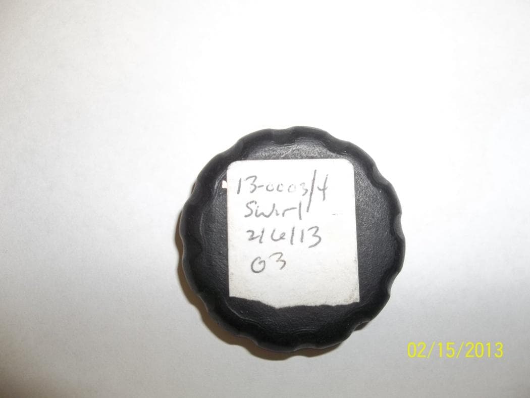
Click to zoom
Application Details
- Equipment Class
- DXX - Part 15 Low Power Communication Device Transmitter
- Date of Grant
- Feb 25, 2013
- Application Purpose
- Original Equipment
- Date of Application
- Feb 25, 2013
- Equipment Note
- MICRO-LOCATION BEACON
- Frequency Range
- 2402.00000000 - 2480.00000000
- Company
- Swirl Networks
- Country
- United States
Documents & Files
Document Text
Text extracted from the exhibit documents filed with the FCC. Open a document above to read the original.
Users Manual
Version 1.0 Swirl Networks 1 SWIRL Sensor Model: SW-001 Micro-Location Positioning & In-Store Services for SWIRL Personal Shopping Assistant Mobile Application Getting Started Guide Version 1.0 Swirl Networks 2 FCC Compliance Statement This device complies with Part 15 of the FCC Rules. Operation is subject to the following two conditions: (1) this device may not cause harmful interference, and (2) this device must accept any interference received, including interference that may cause undesired operation. CAUTION: Change or modification not expressly approved by the party responsible for compliance could void the user’s authority to operate this equipment. This equipment has been tested and found to comply with the limits for a Class B digital device, pursuant to Part 15 of the FCC Rules. These limits are designed to provide reasonable protection against harmful interference in a residential installation. This equipment generates, uses and can radiate radio frequency energy and, if not installed and used in accordance with the instructions, may cause harmful interference to radio communications. However, there is no guarantee that interference will not occur in a particular installation. If this equipment does cause harmful interference to radio or television reception, which can be determined by turning the equipment off and on, the user is encouraged to try to correct the interference by one or more of the following measures: --Reorient or relocate the receiving antenna. --Increase the separation between the equipment and receiver. --Connect the equipment into an outlet on a circuit different from that to which the receiver is connected. --Consult the dealer or an experienced radio/TV technician for help. CAUTION: Any changes or modifications not expressly approved by the grantee of this device could void the user's authority to operate the equipment. RF Exposure Warning This equipment must be installed and operated in accordance with provided instructions and the antenna(s) used for this transmitter must be installed to provide a separation distance of at least 2.5 cm from all persons and must not be co-located or operating in conjunction with any other antenna or transmitter. End-users and installers must be provided with antenna installation instructions and transmitter operating conditions for satisfying RF exposure compliance. Industry Canada Compliance Statement This device complies with Industry Canada licence-exempt RSS standard(s). Operation is subject to the following two conditions: (1) this device may not cause interference, and (2) this device must accept any interference, including interference that may cause undesired operation of the device. Le présent appareil est conforme aux CNR d'Industrie Canada applicables aux appareils radio exempts de licence. L'exploitation est autorisée aux deux conditions suivantes : (1) l'appareil ne doit pas produire de brouillage, et (2) l'utilisateur de l'appareil doit accepter tout brouillage radioélectrique subi, même si le brouillage est susceptible d'en compromettre le fonctionnement. Version 1.0 Swirl Networks 3 SWIRL Sensor Components A B C D A – Top Case with Mounted Circuit Board and Battery Holder B – Bottom Case C – CR2032 3V Lithium Coin Cell Battery D – Adhesive Mounting Strip Version 1.0 Swirl Networks 4 Getting Started 1. Unscrew the Swirl Sensor protective case by gripping the larger, topside portion of the case with one hand and the smaller, bottom section of the case with your other hand. Twist the top section of the case in a counter clockwise manner while holding the bottom section firm. Sensor case will separate after one and a half full turns. 2. Turn the larger, top section case upside down to reveal the enclosed circuit board and plastic battery holder. Version 1.0 Swirl Networks 5 3. Place the provided CR2032 3V battery in the battery holder by positioning the positive (+) marked face of the battery in the upright position. Slide the battery into the holder at an angle pushing the battery beyond the two protruded plastic guards and against the rounded metal guards. Once guards are cleared, slightly push the battery down allowing it to snap firmly into place. Version 1.0 Swirl Networks 6 4. Re-assemble the top and bottom case section by screwing together until snug. Do not over tighten 5. Once the battery is properly installed, the Swirl Sensor will automatically start broadcasting and advertising its presence. The Version 1.0 Swirl Networks 7 sensor will automatically be placed into a continuous broadcasting state until the battery is either removed or is depleted of its power. Note: The sensor does not provide any audio or visual indication upon battery insertion. Sensor operation and battery levels are monitored within the Swirl Administration Console. 6. To position the sensor, peel off one side of the protective film liner on the provided adhesive strip and apply to the flat section of the bottom case. Peel off the top film liner and place in desired location (see Best Practices for Sensor Placement document for placement recommendations and guidelines). Apply moderate pressure for 5-10 seconds. 7. To remove the sensor from a wall or fixture, twist the bottom section of the sensor case in either a clockwise or counter clockwise manner until the adhesive separates from the case leaving it exposed on the wall or fixture. Remove the adhesive left behind by scraping a corner with your fingertip and peeling and rolling into a ball until it’s fully removed. Version 1.0 Swirl Networks 8 Note: The broadcasting area of the Swirl Sensor is fixed and controlled by a constant power output setting configured in the sensor’s firmware and is not configurable. Configuring the desired area and distance that a sensor will record a detection event can be set and configured in the Swirl Console. 8. Once a sensor’s battery is properly inserted and positioned, the sensor must be activated in the Swirl Console (refer to the Swirl Co…
Text truncated - open the document above for the full version.
Cover Letter(s)
FCC Confidentiality Request February 19, 2013 Timco Engineering PO Box 370 Newberry, FL 32669 RE : FCC ID: RMS021764-SW Dear Applications Examiner: With regards to the exhibits submitted in support of the application for the FCC ID referenced above, please classify the following as confidential under the provision of 47 CFR 0.459: -Schematics - File Name: 13-0003.Swirl.SW-001.CONFIDENTIAL Schematics.pdf - Block Diagram – File Name: 13-0003.Swirl.SW-001.CONFIDENTIAL Block Diagram.pdf -Operational Description – File Name: 13-0003.Swirl.SW-001.CONFIDENTIAL ToO.pdf These exhibits contain technical information that the grantee deems to be sensitive and proprietary. Therefore this information cannot be published. If this information were to be made public it could be used to the disadvantage of the applicant in the marketplace. Sincerely, Sandi McEnery US Tech (Authorized Agent) 3505 Francis Circle Alpharetta, GA 30004 PH: 770-740-0717 Fax: 770-740-1508 www.ustech-lab.com
External Photos
US Tech FCC Part 15.249/ RSS 210 Test Report: 13-0003 Date: February 18, 2013 Model(s): SW-001 FCC ID: RMS021764-SW IC: 10872A-021762SW Customer: Swirl Networks APPENDIX H – EXTERNAL PHOTOGRAPHS Photo 1 – Top of EUT Photo 2 – Bottom of EUT
ID Label/Location Info
9mm 46mm 3mm 25mm SWIRL Label Info Backside Posi<on
Internal Photos
US Tech FCC Part 15.249/ RSS 210 Test Report: 13-0003 Date: February 18, 2013 Model(s): SW-001 FCC ID: RMS021764-SW IC: 10872A-021762SW Customer: Swirl Networks APPENDIX I – INTERNAL PHOTOGRAPHS PHOTOS 1 and 2 – EUT, OPENED US Tech FCC Part 15.249/ RSS 210 Test Report: 13-0003 Date: February 18, 2013 Model(s): SW-001 FCC ID: RMS021764-SW IC: 10872A-021762SW Customer: Swirl Networks PHOTO 3 – TOP OF PCB PHOTO 4 – BOTTOM OF PCB
Test Report
Page 1 of 29 Application for US Code Title 47, Part 2, Subpart J, Section 2.947, Certification Per Part 15, Subpart C, for Intentional Radiators, Section 15.249, Intentional Radiator Operating within the Band 2400 MHz to 2483.5 MHz. And US Code Title 47, Part 2, Subpart J, Section 2.902, Verification Per Part 15, Subpart B, for Unintentional Radiators, section 15.101, 15.107 and 15.109 For the Swirl Networks Swirl Model: SW-001 Manufactured by Swirl Networks UST Project: 13-0003 Test Date(s): February 6-13, 2013 Issue Date: February 18, 2013 3505 Francis Circle Alpharetta, GA 30004 PH: 770-740-0717 Fax: 770-740-1508 www.ustech-lab.com Page 2 of 29 I certify that I am authorized to sign for the test facility and that all of the statements in this report and in the Exhibits attached hereto are true and correct to the best of my knowledge and belief: US TECH (Agent Responsible For Test): By: Name: Alan Ghasiani Title: Consulting Engineer - President Date: February 18, 2013 This report shall not be reproduced except in full. This report may be copied in part only with the prior written approval of U.S. Technologies. The results contained in this report are subject to the adequacy and representative character of the sample provided. 3505 Francis Circle Alpharetta, GA 30004 PH: 770-740-0717 Fax: 770-740-1508 www.ustech-lab.com US Tech FCC Part 15.249/ RSS 210 Test Report: 13-0003 Date: February 18, 2013 Model(s): SW-001 FCC ID: RMS021764-SW IC: 10872A-021764SW Customer: Swirl Networks Page 3 of 29 MEASUREMENT/TECHNICAL REPORT COMPANY NAME: Swirl Networks MODEL(S): SW-001 FCC ID: RMS021764-SW IC ID: 10872A-021764SW DATE: February 18, 2013 This report concerns (check one): Original grant X Class II change_____ Equipment type: Intentional Radiator Operating within the bands 2400-2483.5 MHz Deferred grant requested per 47 CFR 0.457(d) (1) (ii)? yes_____ No X If yes, defer until:_________________ date N.A. agrees to notify the Commission by N.A. date of the intended date of announcement of the product so that the grant can be issued on that date. Report prepared by: US Tech 3505 Francis Circle Alpharetta, GA 30004 Phone Number: (770) 740-0717 Fax Number: (770) 740-1508 US Tech FCC Part 15.249/ RSS 210 Test Report: 13-0003 Date: February 18, 2013 Model(s): SW-001 FCC ID: RMS021764-SW IC: 10872A-021764SW Customer: Swirl Networks Page 4 of 29 SUMMARY OF TEST REQUIREMENTS FCC Requirement Title Disposition 15.205 Restricted Bands Pass 15.207 Intentional Radiator Power Line Conducted Pass Emissions 15.209 Intentional Radiator Radiated Emissions Pass 15.249(a) Fundamental Field Strength Pass 15.107 Unintentional Radiator Power Line Conducted Pass Emissions 15.109 Unintentional Radiator Radiated Emissions Pass N/A = Not applicable for this unit. US Tech FCC Part 15.249/ RSS 210 Test Report: 13-0003 Date: February 18, 2013 Model(s): SW-001 FCC ID: RMS021764-SW IC: 10872A-021764SW Customer: Swirl Networks Page 5 of 29 Table of Contents 1 General Information ........................................................................................ 7 1.1 Purpose of this Report .............................................................................. 7 1.2 Product Description ................................................................................... 7 1.3 Related Submittal(s)/Grant(s) ................................................................... 7 2 Tests and Measurements ............................................................................... 8 2.1 Configuration of Tested System ................................................................ 8 2.2 EUT Characterization ................................................................................ 9 2.3 Test Facility ............................................................................................... 9 2.4 Test Equipment ....................................................................................... 10 2.5 Modifications to EUT ............................................................................... 10 2.6 Measurement Standards (CFR 15.31) .................................................... 11 2.7 Frequency Range of Radiated Measurements (CFR 15.33) ................... 11 2.7.1 Frequency Range for Intentional Radiators ................................................ 11 2.7.2 Frequency Range for Unintentional Radiators ............................................ 11 2.7.3 Measurement Detector Function and Bandwidth (CFR 15.35) ................... 11 2.8 Antenna Requirement (CFR 15.203) ...................................................... 14 2.9 Intentional Radiator, Power Line Conducted Emissions (CFR 15.207) ... 14 2.10 Intentional Radiator, Radiated Emissions (CFR 15.249 (a), (e)) ............. 14 2.11 Restricted Bands of Operation (CFR 15.205) ......................................... 14 2.12 Band Edge Measurements (CFR15.249(d)) ............................................ 21 2.12.1 High Band Edge ...................................................................................... 21 2.12.2 Low Band Edge ...................................................................................... 23 2.13 Unintentional Radiator, Power Conducted Emissions (CFR 15.107) ...... 25 2.14 Unintentional Radiator, Radiated Emissions (CFR 15.109) .................... 27 2.15 Measurement Uncertainty ....................................................................... 29 2.15.1 Conducted Emissions Measurement Uncertainty .................................... 29 2.15.2 Radiated Emissions Measurement Uncertainty ....................................... 29 List of Tables Table 1 - EUT and Peripherals ............................................................................. 9 Table 2 - Test Instruments used for Evaluation .................................................. 10 Table 3 - Allowed Antenna(s) ........................................................................... 14 Table 4 - Peak Fundamental and Harmonic…
Text truncated - open the document above for the full version.
Test Setup Photos
US Tech FCC Part 15.249/ RSS 210 Test Report: 13-0003 Date: February 18, 2013 Model(s): SW-001 FCC ID: RMS021764-SW IC: 10872A-021762SW Customer: Swirl Networks TEST CONFIGURATION PHOTOGRAPHS Photo 1 - Test Configuration of EUT Photo 2 – Test Configuration of EUT Below 30 MHz Testing US Tech FCC Part 15.249/ RSS 210 Test Report: 13-0003 Date: February 18, 2013 Model(s): SW-001 FCC ID: RMS021764-SW IC: 10872A-021762SW Customer: Swirl Networks Photo 3 – Test Configuration of the EUT Above 30 MHz Testing Photo 3 – Test Configuration of the EUT Above 1 GHz Testing
Contact Information
Applicant
Todd Boes(VP Products)
Test Firm
US TechGeorge Yang
Technical Specifications
| # | Rule Parts | Frequency Range | Power Output |
|---|---|---|---|
| 1 | 15C | 2.40 GHz - 2.48 GHz | - |
Other Applications from Swirl Networks
RMS0217644XAA
Dec 14, 2015Low power transmitter
Equipment Class
DXX - Part 15 Low Power Communication Device Transmitter
RMS0217642477
Jan 28, 2014micro location beacon
Equipment Class
DXX - Part 15 Low Power Communication Device Transmitter
RMS0217642XAA
Sep 19, 2013MICRO LOCATION BEACON
Equipment Class
DXX - Part 15 Low Power Communication Device Transmitter