RN489896162-B01342.4G RF module
SHUN HU TECHNOLOGY CO., LTD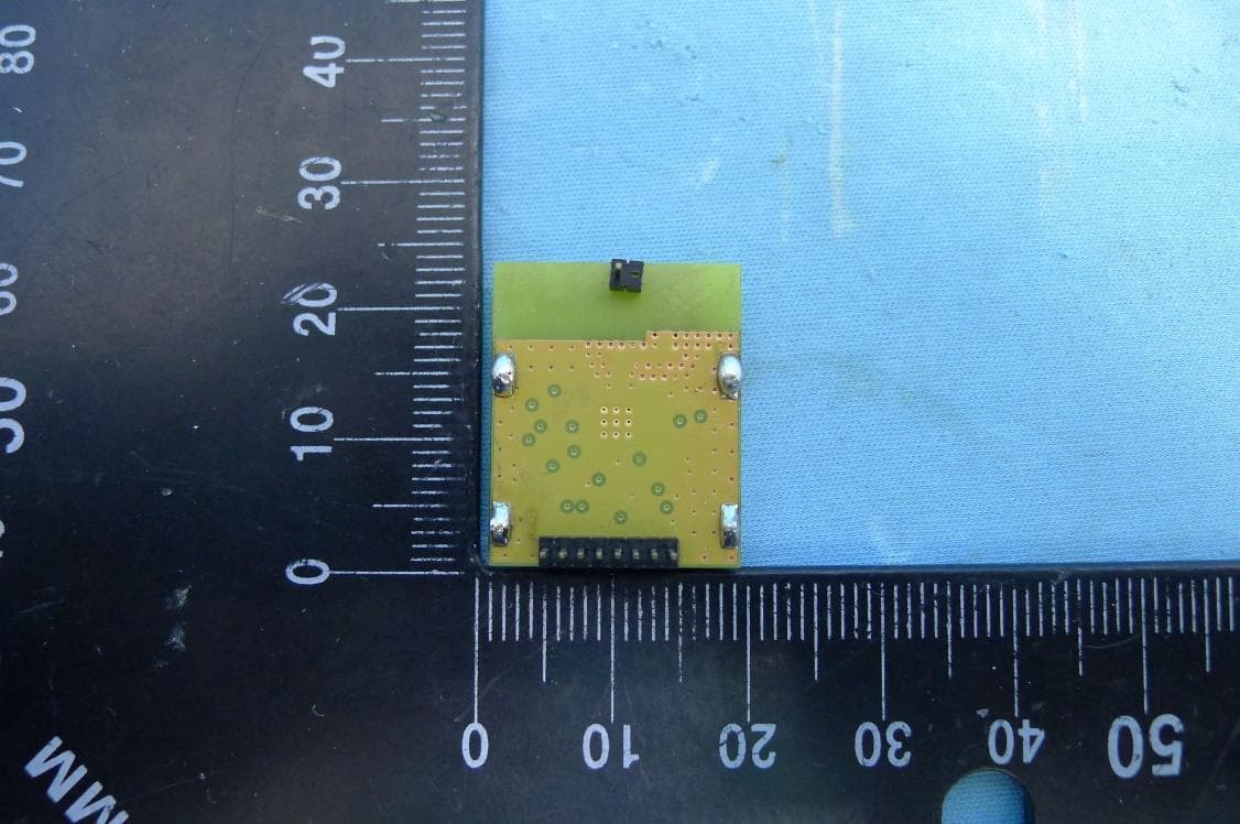
Click to zoom
Application Details
- Equipment Class
- DTS - Digital Transmission System
- Date of Grant
- Jul 29, 2021
- Application Purpose
- Original Equipment
- Date of Application
- Jul 29, 2021
- Equipment Note
- 2.4G RF module
- Frequency Range
- 2401.00000000 - 2478.00000000
- Company
- SHUN HU TECHNOLOGY CO., LTD
- Country
- Taiwan
Documents & Files
Document Text
Text extracted from the exhibit documents filed with the FCC. Open a document above to read the original.
Users Manual
User Manual Model: B0134 Product Description The B0134 RF Transceiver Module is a compact surface-mounted module for multi- channel RoLa operation in the 2400 MHz ISM band. The module is completely shielded and pre-certi ed for operation under US radio regulations for license-free use. Technical data Block Diagram Theory of Operation/Technical Description - RF circuit function: The major part of this IC is a 2401-2478 MHz compliant transceiver. - RF signal ow: The Control signal is encoded into a Data Stream to be the modulation input for the transceiver. -Description of Antenna system: The antenna shall be connected to the RF pin. The RF pin is matched to 50 Ohm. If the antenna connector is placed away from the module at the motherboard, the track between the RF pin and the connector should be a 50 Ohm transmission line. RF Tranceiver CC1200 Filter 1.8-3.7 V SI SCLK SO RESET GPIO CSN GND Pin Assignment GND ANT GND VCC SI SCLK SO RESET GPIO CSN GND The nal host product must be submitted to SHUN HU Technology Co., Ltd. for con rmation that the installation of the module into the host is in compliance. with the regulations of FCC and IC Canada. Speci cally, if an antenna other than the model documented in the Filing is used, a Class 2 Permissive Change must be led with the FCC. TCXO 52Mhz Dimensions Frequency Modulation method Channel bandwidth Supply voltage 30.38×18.5×7.45(mm) 2.4GHz RoLa 500KHz Temperature range -40°C+85°C 1.8-3.7 Volt RN489896162JK915 FCC ID RN489896162-B0134 FCC ID User Manual Mechanical Drawing IC Statement This device complies with Industry Canada licence-exempt RSS standard(s). Operation is subject to the following two conditions: (1) this device may not cause interference, and (2) this device must accept any interference, including interfer- ence that may cause undesired operation of the device. Le présent appareil est conforme aux CNR d'Industrie Canada applicables aux appareils radio exempts de licence. L'exploitation est autorisée aux deux conditions suivantes : (1) l'appareil ne doit pas produire de brouillage, et (2) l'utilisa- teur de l'appareil doit accepter tout brouillage radioélectrique subi, même si le brouillage est susceptible d'en comprom- ettre le fonctionnement. FCC Part 15 * This device complies with Part 15 of the FCC Rules. Operation is subject to the following two conditions: (1) this device may not cause harmful interference and (2) this device must accept any interference received, including interference that may cause undesired operation * You are cautioned that changes or modi cations not expressly approved by the party responsible for compliance could void your authority to operate the equipment. NOTE: This equipment has been tested and found to comply with the limits for a Class B digital device, pursuant to part 15 of the FCC Rules. These limits are designed to provide reasonable protection against harmful interference in a residential installation. This equipment generates, uses and can radiate radio frequency energy and, if not installed and used in accordance with the instructions, may cause harmful interference to radio communications. However, there is no guarantee that interference will not occur in a particular installation. If this equipment does cause harmful interference to radio or television reception, which can be determined by turning the equipment o and on, the user is encouraged to try to correct the interference by one or more of the following measures: —Reorient or relocate the receiving antenna. —Increase the separation between the equipment and receiver. —Connect the equipment into an outlet on a circuit di erent from that to which the receiver is connected. —Consult the dealer or an experienced radio/TV technician for help. Changes or modi cations not expressly approved by the party responsible for compliance could void the user’s authority to operate the equipment. Antenna gain: 2dBi D 2.5 1 8.98 2.5 2.5 2.5 1.1 5.06 18 22.5 14.4 3.1 4.8 Label User Manual The module has received Federal Communications Commission (FCC) CFR47 Telecommunications, Part 15 Subpart C "Intentional Radiators" modular approval in accordance with Part 15.212 Modular Transmitter approval. Modular approval allows the end user to integrate the module into a nished product without obtaining subsequent and separate FCC approvals for intentional radiation, provided no changes or modi cations are made to the module circuitry. Changes or modi cations could void the user's authority to operate the equipment. The end user must comply with all of the instructions provided by the Grantee, which indicate installation and/or operating conditions necessary for compliance. The nished product is required to comply with all applicable FCC equipment authorizations regulations, requirements and equipment functions not associated with the transmitter module portion. For example, compliance must be demonstrated to regulations for other transmitter components within the host product; to requirements for unintentional radiators (Part 15 Subpart B "Unintentional Radiators"), such as digital devices, computer peripherals, radio receivers, etc.; and to additional authorization requirements for the nontransmitter functions on the transmitter module (i.e., Veri cation, or Declaration of Conformity) (e.g., transmitter modules may also contain digital logic functions) as appropriate. LABELING AND USER INFORMATION REQUIREMENTS The B0134 module has been labeled with its own FCC ID number, and if the FCC ID is not visible when the module is installed inside another device, then the outside of the nished product into which the module is installed must also display a label referring to the enclosed module. This exterior label can use wording as follows: Contains Transmitter Module FCC ID:RN489896162-B0134 or Contains FCC ID: RN489896162-B0134 This device complies with Part 15 of the FCC Rules. Operation is subject to the following two conditions: (1) this device may not …
Text truncated - open the document above for the full version.
External Photos
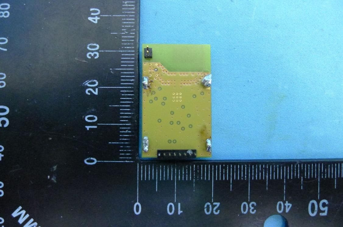
Report No.: 2103TWA101-U1 Product: 2.4G RF module Brand Name: JUUKO Model Number: B0134 1 of 3 External Photograph (1) EUT Photo (2) EUT Photo Report No.: 2103TWA101-U1 2 of 3 (3) EUT Photo (4) EUT Photo Report No.: 2103TWA101-U1 3 of 3 (5) EUT Photo (6) EUT Photo
ID Label/Location Info
Label & Label location
Internal Photos
Report No.: 2103TWA101-U1 Product: 2.4G RF module Brand Name: JUUKO Model Number: B0134 1 of 2 Internal Photograph (1) EUT Photo (2) EUT Photo Report No.: 2103TWA101-U1 2 of 2 (3) EUT Photo (4) EUT Photo
RF Exposure Info
Maximum Permissible Exposure FCC ID RN489896162-B0134 Model No. B0134 RF Specification 2.4GHz (2401~2478MHz) According to FCC 1.1310: The criteria listed in the following table shall be used to evaluate the environment impact of human exposure to radio frequency (RF) radiation as specified in 1.1307(b) Calculation Formula: Pd = (Pout*G)/(4*pi*r 2 ) Where Pd = power density in mW/cm 2 Pout = output power to antenna in mW G = gain of antenna in linear scale Pi = 3.1416 r = distance between observation point and center of the radiator in cm Calculation Result: Mode Frequency Band (MHz) Output Power (dBm) Output Power (mW) Antenna Gain (dBi) Distance (cm) Power Density (mW/cm 2 ) Limit (mW/cm 2 ) 2.4GHz 2401~2478 13.147 167.1 2 20 0.0065 1
Test Report
MRT Technology (Taiwan) Co., Ltd Report No.: 2103TWA101-U1 Phone: +886-3-3288388 Report Version: 1.0 Fax: +886-3-3288918 Issue Date: 2021-07-07 Web: www.mrt-cert.com FCC ID: RN489896162-B0134 Page Number: 1 of 52 FCC ID: RN489896162-B0134 APPLICANT: SHUN HU Technology Co., Ltd. Application Type: Certification Product: 2.4G RF module Model No.: B0134 FCC Classification: (DTS) Digital Transmission System FCC Rule Part(s): Part 15.247 Test Procedure(s): ANSI C63.10-2013 Received Date: March 4 ,2021 Test Date: June 22~24 ,2021 MEASUREMENT REPORT FCC PART 15.247 Tested By : ( Eric Lin ) Reviewed By : ( Paddy Chen ) Approved By : ( Chenz Ker) The test results only relate to the tested sample. This equipment has been shown to be capable of compliance with the applicable technical standards as indicated in the measurement report and was tested in accordance with the measurement procedures specified in ANSI C63.10. Test results reported herein relate only to the item(s) tested. The test report shall not be reproduced except in full without the written approval of MRT Technology (Taiwan) Co., Ltd. Report No.: 2103TWA101-U1 FCC ID: RN489896162-B0134 Page Number: 2 of 52 Revision History Report No. Version Description Issue Date Note 2103TWA101-U1 1.0 Original Report 2021-07-07 Report No.: 2103TWA101-U1 FCC ID: RN489896162-B0134 Page Number: 3 of 52 CONTENTS Description Page §2.1033 General Information ......................................................................................................... 5 1. INTRODUCTION ..................................................................................................................... 6 1.1. Scope .................................................................................................................................... 6 1.2. MRT Test Location ................................................................................................................ 6 2. PRODUCT INFORMATION ..................................................................................................... 7 2.1. Equipment Description .......................................................................................................... 7 2.2. Product Specification Subjective to this Standard .................................................................. 7 2.3. Test Mode ............................................................................................................................. 7 2.4. Operation Frequency / Channel List ...................................................................................... 8 2.5. Test Configuration ............................................................................................................... 10 2.6. Test Software ...................................................................................................................... 10 2.7. EMI Suppression Device(s)/Modifications ........................................................................... 10 2.8. Labeling Requirements ....................................................................................................... 10 3. DESCRIPTION of TEST ......................................................................................................... 11 3.1. Evaluation Procedure .......................................................................................................... 11 3.2. AC Line Conducted Emissions ............................................................................................ 11 3.3. Radiated Emissions ............................................................................................................ 12 4. ANTENNA REQUIREMENTS ................................................................................................ 13 5. TEST EQUIPMENT CALIBRATION DATE ............................................................................ 14 6. MEASUREMENT UNCERTAINTY ......................................................................................... 15 7. TEST RESULT ...................................................................................................................... 16 7.1. Summary ............................................................................................................................. 16 7.2. 6dB Bandwidth Measurement ............................................................................................. 17 7.2.1. Test Limit ......................................................................................................................... 17 7.2.2. Test Procedure used ....................................................................................................... 17 7.2.3. Test Setting ..................................................................................................................... 17 7.2.4. Test Setup ....................................................................................................................... 17 7.2.5. Test Result ...................................................................................................................... 18 7.3. Output Power Measurement ................................................................................................ 19 7.3.1. Test Limit ......................................................................................................................... 19 7.3.2. Test Procedure Used ....................................................................................................... 19 7.3.3. Test Setting ..................................................................................................................... 19 7.3.4. Test Setup ....................................................................................................................... 19 7.3.5. Test Result of Output Power ............................................................................................ 20 7.4. Power Spectral Density Measurement ..…
Text truncated - open the document above for the full version.
Test Setup Photos
Report No.: 2103TWA101-U1 Product: 2.4G RF module Brand Name: JUUKO Model Number: B0134 1 of 3 Test Photograph Description: Front View of Conducted Emission Test Setup Description: Back View of Conducted Emission Test Setup Report No.: 2103TWA101-U1 2 of 3 Description: Radiated Emission Test Setup for below 1GHz Description: Radiated Emission Test Setup for above 1GHz Report No.: 2103TWA101-U1 3 of 3 Description: Conducted Emission Test Setup
Contact Information
Applicant
Hsin-hui Evan Yu(general manager)
Test Firm
MRT Technology (Taiwan) Co.,LtdChenz Ker
Technical Specifications
| # | Rule Parts | Frequency Range | Power Output |
|---|---|---|---|
| 1 | 15C | 2.40 GHz - 2.48 GHz | 20.60 mW |
Other Applications from SHUN HU TECHNOLOGY CO., LTD
RN489896162-B0129
Jul 29, 20212.4G RF module
Equipment Class
DTS - Digital Transmission System
RN489896162JK01
Jun 05, 2013K series Remote Control Device
Equipment Class
DXX - Part 15 Low Power Communication Device Transmitter