RNGH200RFXTwo Way Personal Communicator
Hunetec Co., Ltd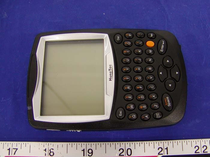
Click to zoom
Application Details
- Equipment Class
- PCB - PCS Licensed Transmitter
- Date of Grant
- Dec 22, 2003
- Application Purpose
- Original Equipment
- Date of Application
- Dec 22, 2003
- Equipment Note
- Two Way Personal Communicator
- Frequency Range
- 896.00000000 - 902.00000000
- Company
- Hunetec Co., Ltd
- Country
- South Korea
Documents & Files
Document Text
Text extracted from the exhibit documents filed with the FCC. Open a document above to read the original.
Users Manual
H-200 H200 User’s Manual August 27, 2003 HuneTec Co.,Ltd Contents General Information ................................................................4 Introduction ................................................................................4 RF Specification ............................................................................4 Physical specification ......................................................................4 H200 PC Link ..............................................................................6 Manufacturer ...............................................................................6 Technical Theory ...................................................................7 Controller Circuit Descriptions .............................................................7 Transceiver Circuit Descriptions........................................................11 User’s Manual .....................................................................16 Before You Start ......................................................................19 Getting Started .........................................................................29 Read Message ............................................................................31 Write Message ...........................................................................41 Contact .................................................................................45 Scheduler .................................................................................50 Task .......................................................................................54 Memo ....................................................................................56 Preference .............................................................................58 Alarm .....................................................................................66 Calculator ................................................................................68 Lock .......................................................................................69 World Clock ........................................................................ ....70 Game .....................................................................................71 Tx Set .....................................................................................73 Alert ......................................................................................74 My Mail ..................................................................................75 H-200 PC Link Program ...............................................................76 Device and Battery Care ...............................................................82 Troubleshooting .........................................................................83 Safety Information .......................................................................85 Part List ............................................................................86 Logic & RF Board Part List ............................................................86 Keypad Board Part List .................................................................90 Block Diagram ....................................................................91 Controller Functional Block Diagram ................................................92 Transceiver Functional Block Diagram ..............................................93 Schematic Diagram ..............................................................94 Controller Schematic Diagram..........................................................95 Transceiver Schematic Diagram ........................................................96 Keypad Schematic Diagram ...........................................................97 General Information Introduction # Small Size and Light Weight for Portability # ReFLEX Two-way Messaging & E-Mailing # Graphic User Interface for Easy Use # Personal Information Management Support # PC Connectivity for Data Back-up and Restoring with Desktop PC RF Specification - Receiver Frequency Bands: 929 MHz - 932 MHz , 935 MHz - 942 MHz Channel Spacing: 6.25 kHz , 10 kHz and 12.5 kHz Bit Rate: 1600/2 level FSK , 3200/2 level FSK , 3200/4 level FSK , 6400/4 level FSK Frequency Deviation: +/- 800 Hz and +/- 2400 Hz Signaling: 2/4 level FSK - Transmitter Frequency Range: 896-902 MHz Bit Rate: 800, 1600, 6400 and 9600 bps Channel Spacing: 12.5 KHz in 6.25 KHz steps Frequency Deviation: +/- 800 Hz and +/- 2400 Hz Signaling: 4 level FSK Physical Specification # Operating temperature range: -10°C ~ +50°C (32F~122F) # Dimensions Size: 105×70×18mm Weight: 120g # Power Consumption Batteries: Li-Ion 700mA rechargeable battery Stand-by Time: 7 days Recharging Time: 2 hours Rx Consummation: 45mA Tx Consummation: 800mA Idle Current: 1.2mA # Display Full-graphics high-contrast screen Resolution 160×128 dots Lines by 24 characters Electro-Luminescent back lighting 4 gray LCD Multi Font (Large / Small) Display # Keypad 32 QWERTY Keyboard slide keys 4 navigation keys # Accessories Mains charger Belt clip H200 PC Link software & editor cable H200 PC Link # Edit and back up address book memory # Send and receive messages by using a PC keyboard # Compose and change Bell melodies with H200 PC Link Maestro Manage settings Manufacturers Hunetec Co.,LTD 10th Hung-Kook Bldg.,Soonae-dong, Bundang-ku, Sungnam-si, Kyungki-do, Korea 463-020 Telephone : +82-31-712-6868 Facsimile : +82-31-712-6889 Technical Theory Controller Circuit Descriptions The controller section consists of the following main functional blocks(see Figure 2-1) # Functional Controller (U25) # Message Storage (U24) # Primary Code Storage (U23) # Power Management (U304) # Display Module # Backlighting (U3) # Serial Interface (U28) # Audio (U31) ADDRESS/DATA ROM_CE EXT_DET_SENSE KEYIN[1:6] SOUND1 VIB_EN #RESET FLASH SRAM KEYPAD VIBRATOR INTERFACE CONNECTOR POWER & RESET DISPLAY / KEYPAD BACKLIGHT TRANSDUCER ADDRESS/D…
Text truncated - open the document above for the full version.
Cover Letter(s)
Federal Communications Commission Authorization and Evaluation Division Confidentiality Request regarding application for certification of FCC ID: (Place FCC ID here) Pursuant to Sections 0.457 and 0.459 of the Commission’s Rules, we hereby request confidential treatment of information accompanying this application as outlined below: - Circuit_Diagram - Operational description - RX_TX_SETTING MANUAL - Part List The above materials contain trade secrets and proprietary information not customarily released to the public. The public disclosure of these materials may be harmful to the applicant and provide unjustified benefits to its competitors. The applicant understands that pursuant to Section 0.457 of the Rules, disclosure of this application and all accompanying documentation will not be made before the date of the Grant for this application. Sincerely, JAE_MIN HYEON
External Photos
Hunetec Co., Ltd FCC ID: RNGH200 APPENDIX C - EUT PHOTOGRAPHS Chassis - Front View Chassis – Rear View
ID Label/Location Info
APPENDIX A - FCC ID LABELING AND LOCATION Proposed FCC ID Labeling Proposed FCC ID Location Rear Side of EUT / Proposed Label Location FCC ID: RNGH200
Operational Description
7n Human Network Technology Controller Circuit Descriptions The controller section consists of the following main functional blocks(see Figure 2-1) Functional ControUer (U2S) # . Message Storage (U24) Primary Code Storage (U23) # . Power Management (U304) Display Module * Backlighting (U3) * Serial Interface (V28) # # Audio (U31) HuneTec Confidential Proprietllry COPYRIGHT. ; 2003 HuneTec CO., Ltd. All Rights Reserved 8/8 Figure 2-1. Controller Functional Block Diagram 1. Functional Controller The functional controller (U2S) provides user interface of the unit. The functional controller affects the following components : Display Module # Message storage (U24) # Primary Code Storage (U23) #~(U26) # Alert generators (vibrator at VI7; transducer at U30) # Display (U7) and Keypad Backlight # Serial commWlication (U28) H""eTec Co"flde"ti41 Proprietary COPYRIGHT. :2003 H""eTec CO., Ltd. All Rights Reserved 9/9 Human Network Technology Primary code storage (U23) . 2. Digital Signal Processor The digital signal processor (014) is responsible for the decoding received infonnation. 3. ~essage Storage The message storage IC (U24) is a 4M bit SRAM (Static Random Access Memory) contained in a 44-pin package 4. Primary Code Storage The primary code storage IC (U23) is a 16-megabit flash memory IC contained in a 48- pin package. s. Power Management After Battery voltage is authorized, voltage is authorized to internal LDO Regulator (U13, Ul8, U410, U411, U412) and Reset genemtor through VIN of Power & reset IC (U304). CPU is initialized through Reset signal which is input to CPU as Reset IN. Output power Vout(+3V) for Power & reset IC is used for Logic such as Digital Part of Audio IC and CPO. Output power Vout (+3V) fir ~rnal Regulator is used for Analog part of Audio IC and VCTCXO. PLL of Transceiver. Regulator is used for authorization for regular voltage ofEL through Battery voltage. 6. Display Module HuneTec Confidential Proprietary COPYRIGHT. ; 2003 HuneTec CO., Ltd. All Rights Reserved IfYIO Human Network Technology The display driver is a flex circuit that drives Lines by 24 characters display. This circuit attaches to the controller at contacts display module. The functional controller (U25) provides sole control over the driver. The display driver has an internal voltage triple that generates the appropriate voltage levels needed to drive the display glass. 7. Backlight The backlight consists of the following elements: ..Electro-Luminescent (EL) panels An EL driver (U3) # . EL contacts When active, the EL panel draws approximately 90 volts peak-tO-peak (200Hz) from the driver. 8. Serial Port Interface The serial port interface provides a connection between the HRD-lOO communicator and programming fixture. AUDIO 9. Audio IC (U31) is a mono bridged audio power amplifier with DC voltage volume control. HuneTec Confidential Proprietary COPYRIGHT. I 2003 HuneTec CO., Ltd. All Rights Reserved II/II Human Network Technology Transceiver Circ uit Descriptions Specifications 1. Receiver Specification Item Frequency Channel Spacing Bit Rate 92H32MHz, 93S-942MHz 1205KHz/10KHz 1600 --96OObps 2 or 4 Level FSK 800Hz and 2400Hz Signaling Modulation Frequency Deviation Receiver Sensitivity 20uV/M wid180 cbar(TBD) Frequency Accuracy _0 Ippm > 50dB from Sensitivity to -8OdBm > 4OdB at - 70dB Signal Level > 30dB at -6OdB Signal Level Adjacent Channel Rejection < lSdB at-lO5dBm < 10dB at-lO2dBm < 6dB at -95dBm Co-Channel Rejection > 55dB at-IOSdBm > 55dB at-IO5dBm > 50dB from Sensitivity to -8(kIBm > 4OdB at - 70dB Signal Level > 30dB at -6OdB Signal Level Spurious Response Rejection Image Rejection Inter-Modulation Distortion Rejection > 1/4 symbol width at -10SdBm and 15dB C/I > 1/4 Symbol width at-1O2dBm and 10dB C/I > 1/4 Symbol width at -55dBm and 6dB C/I Simulcast Delay Spread Tolerance 2.Transmitter Item Specification 896--902MHz Frequency Range HuneTec Confidential Proprietary COPYRIGHT' 1 2003 HuneTec CO., Ltd. All Rights Reserved 12112 Human Network Technology HlineTec Confidential Proprietary COPYRIGHT. I 2003 HlineTec CO., Ltd. All Rights Reserved 13/13 Human Network Technology Circuit Descriptions The following infonnation describes the circuitry specific to HRD-loo pagers with 9OOMHz nnsceivers. See Figure 3-] Figure 3-1 Transceiver Functional Block Diagram The transceiver board consis ts of the following major component sections: #Antenna (ANTI) # Antenna Switch (UI02) # Receiver Automatic Gain Control Circuit # Low Noise Amplifier (U8) # Receiver Surface Acoustic Wave Filter (U2) # Receiver First Mixer (UI04) # Crystal Filter for Fim IF (MCFI) # IF Detector IC (U12) HuneTec Confidential Proprietary COPYRIGHT. 12003 HuneTec CO., Ltd. All Rights Reserved 14/14 Human Network Technology # Decoder (U26) # Operational Amplifier (U9, U19) # Transmit VCO/ Receiver First W VCO (VCOl) Phase locked Loop Power Amplifier (04) Driver Amplifier (U6) Antenna Antenna is for optimal receiving of transmission signal from base station. Reduce damage of weak signal under general external environment and voltage from device to a minimum. 2. Antenna Switch The RF switch is it can be controlled with positive, negative or a combination of both voltages. Some standard implementations include antenna changeover. Transmit/Receive and diversity switching over 3W. AGC (Automatic Gain Controller) Circuit 3. Level of signal which device receiving should maintain regular signal and AGC is for Power control of device. 4. LNA (Low Noise Amplifier) LNA is used for reducing noise to a maximum for optimal signal and amplify signal that need to receive separately. 5. RF SAW (Surface Acoustic Wave) Filter RF Saw Filter is uscxt for band pass for the signal of receiving frequency and reduce other signal except receiving frequency in order to receive selected receiving frequency of Pager. HuneTec Confidential Proprietary COPYRIGHT. ! 2003 HuneTec CO., Ltd. All Rights Reserved IS/IS Human Network Technology 6. Down Converter (MIXER) Down C…
Text truncated - open the document above for the full version.
Parts List/Tune Up Info
1/5 HuneTec Co.,Ltd © 2003Confidentia How to Set Rx Tx Mode for Testing Information of document writer: Dong-Hyun Hwang, S/W engineer, [email protected] creation: August 21, 2003 last update: August 21, 2003 Purpose This document shows how to set Rx/Tx mode for testing Revision history version date comments 0.1 August 21, 2003 start of this document 2/5 HuneTec Co.,Ltd © 2003Confidentia How to set the mode Set Test Mode Press ‘F’ while turning Power Off--> On by turn the bottom switch right to left. Figure 1 3/5 HuneTec Co.,Ltd © 2003Confidentia Set Rx Mode Set Freq: Input the frequency. Input the frequency by Hz on the “Freq” section. Receiver frequency range : 929~932MHz, 935~942MH Figure 2 Ex1) LOW_FREQUENCY : 929.0125MHz -- Æ 929012500 CENTER_ FREQUENCY_1 : 932.9875MHz -Æ 932987500 CENTER_ FREQUENCY_2 : 935.0125MHz - Æ 935012500 HIGH_ FREQUENCY : 941.9875MHz -Æ 941987500 Set Rx Mode: Execute the mode Run the “Rx Mode” (Bottom/Tab Menu) by selecting and enter. 4/5 HuneTec Co.,Ltd © 2003Confidentia Set Tx Mode Set Freq: Input the frequency. Input the frequency by Hz on the ‘Freq’ Input section. Transmitter frequency range : 896~902MHz Set Baud rate: Input the baud rate It must be one of this values...800,1600,6400,9600. Input the baudrate on the “DataRate” section. Figure 3 Ex2) LOW_FREQUENCY : 896.0000MHz -- Æ 896000000 CENTER_ FREQUENCY : 901.0000MHz -Æ 901000000 HIGH_ FREQUENCY : 902.0000MHz -Æ 902000000 Set Tx Mode: Execute the mode Run the “TxMode” (Bottom/Tab Menu) by selecting and enter. ,9600 ,, 5/5 HuneTec Co.,Ltd © 2003Confidentia Cancel Tx,Rx, is initialized Figure 4
Test Report
Note: This test report is specially limited to the above client company and the product model only. It may not be duplicated without prior written consent of Bay Area Compliance Laboratory Corporation. This report must not be used by the client to claim product endorsement by NVLAP or any agency of the U.S. Government. FCC PART 24 & 90 TYPE APPROVAL EMI MEASUREMENT AND TEST REPORT For HUNETEC CO., LTD 10 Fl, Hungkook Bldg, 6-7 Sunae-Dong, Bundang-Ku Kyunggi-Do, South KOREA 463-020 FCC ID: RNGH200RFX 2003-11-20 This Report Concerns: Original Report Equipment Type: PCS Private Land Mobile Data Transceiver Test Engineer: Ling Zhang Report No.: R0310093 Test Date: 2003-11-05, 2003-11-22 Reviewed By: Ming Jing Prepared By: Bay Area Compliance Laboratory Corporation 230 Commercial Street Sunnyvale, CA 94085 Tel: (408) 732-9162 Fax: (408) 732 9164 Hunetec Co., Ltd FCC ID: RNGH200RFX Report # R0310093Rpt Page 2 of 20 FCC Part 24, 90 Type Approval Report TABLE OF CONTENTS 1 - GENERAL INFORMATION..................................................................................................................................3 1.1 PRODUCT DESCRIPTION FOR EQUIPMENT UNDER TEST (EUT) ..............................................................................3 1.2 OBJECTIVE.............................................................................................................................................................3 1.3 RELATED SUBMITTAL(S)/GRANT(S).......................................................................................................................3 1.4 TEST METHODOLOGY............................................................................................................................................3 1.5 TEST FACILITY.......................................................................................................................................................4 2 - SYSTEM TEST CONFIGURATION.....................................................................................................................5 2.1 JUSTIFICATION.......................................................................................................................................................5 2.2 BLOCK DIAGRAM...................................................................................................................................................5 2.3 EQUIPMENT MODIFICATIONS.................................................................................................................................5 2.4 TEST SETUP BLOCK DIAGRAM...............................................................................................................................5 3 - SUMMARY OF TEST RESULTS..........................................................................................................................6 3.1 FREQUENCY AVAILABLE........................................................................................................................................6 3.2 SUMMARY OF TEST RESULTS..................................................................................................................................6 3.3 LABEL REQUIREMENT............................................................................................................................................6 4 - RF POWER OUTPUT .............................................................................................................................................7 4.1 APPLICABLE STANDARD........................................................................................................................................7 4.2 TEST PROCEDURE..................................................................................................................................................7 4.3 TEST EQUIPMENT...................................................................................................................................................7 4.4 TEST RESULTS.......................................................................................................................................................8 5 - MODULATION CHARACTERISTIC ..................................................................................................................9 5.1 APPLICABLE STANDARD........................................................................................................................................9 5.2 TEST PROCEDURE...................................................................................................................................................9 5.3 TEST EQUIPMENT...................................................................................................................................................9 5.4 TEST RESULTS.......................................................................................................................................................9 6 - OCCUPIED BANDWIDTH ..................................................................................................................................11 6.1 APPLICABLE STANDARD......................................................................................................................................11 6.2 TEST PROCEDURE................................................................................................................................................11 6.3 TEST EQUIPMENT.................................................................................................................................................11 6.4 TEST RESULTS.....................................................................................................................................................11 7 - SPURIOUS EMISSIONS AT ANTENNA TERMINALS ..................................................................................13 7.1 APPLICABLE STANDARD......................................…
Text truncated - open the document above for the full version.
Test Report
Note: This test report is specially limited to the above client company and the product model only. It may not be duplicated without prior written consent of Bay Area Compliance Laboratory Corporation. This report must not be used by the client to claim product endorsement by NVLAP or any agency of the U.S. Government. SAR EVALUATION REPORT For HUNETEC CO., LTD 10 Fl, Hungkook Bldg, 6-7 Sunae-Dong, Bundang-Ku Kyunggi-Do, South KOREA 463-020 FCC ID: RNGH200RFX 2003-11-20 This Report Concerns: Original Report Equipment Type: Two Way Personal Communicator Test Engineer: Eric Hong Report No.: R0310093S Test Date: 2003-11-08 Reviewed By: Ling Zhang Prepared By: Bay Area Compliance Laboratory Corporation 230 Commercial Street Sunnyvale, CA 94085 Tel: (408) 732-9162 Fax: (408) 732 9164 HUNETEC CO., LTD FCC ID: RNGH200RFX Report #R0310093S SAR Evaluation Report Page 2 of 46 TABLE OF CONTENTS SUMMARY....................................................................................................................................................................3 1 - REFERENCE ...........................................................................................................................................................5 2 - TESTING EQUIPMENT.........................................................................................................................................6 2.1 EQUIPMENT LIST & CALIBRATION INFO................................................................................................................6 2.2 EQUIPMENT CALIBRATION CERTIFICATE...............................................................................................................6 3 - EUT DESCRIPTION .............................................................................................................................................18 4 - SYSTEM TEST CONFIGURATION...................................................................................................................19 4.1 JUSTIFICATION.....................................................................................................................................................19 4.2 EUT EXERCISE PROCEDURE................................................................................................................................19 4.3 SPECIAL ACCESSORIES.........................................................................................................................................19 4.4 EQUIPMENT MODIFICATIONS...............................................................................................................................19 5 - CONDUCTED OUTPUT POWER MEASUREMENT......................................................................................20 5.1 MEASUREMENT PROCEDURE................................................................................................................................20 5.2 TEST RESULTS.....................................................................................................................................................20 6 - DOSIMETRIC ASSESSMENT SETUP...............................................................................................................22 6.1 MEASUREMENT SYSTEM DIAGRAM.....................................................................................................................23 6.2 SYSTEM COMPONENTS.........................................................................................................................................24 6.3 MEASUREMENT UNCERTAINTY............................................................................................................................28 7 - SYSTEM EVALUATION .....................................................................................................................................29 7.1 SIMULATED TISSUE LIQUID PARAMETER CONFIRMATION...................................................................................29 7.2 EVALUATION PROCEDURES..................................................................................................................................29 7.3 SYSTEM ACCURACY VERIFICATION.....................................................................................................................30 7.4 SAR EVALUATION PROCEDURE...........................................................................................................................34 7.5 EXPOSURE LIMITS................................................................................................................................................35 8 - TEST RESULTS ....................................................................................................................................................36 8.1 SAR TEST DATA..................................................................................................................................................36 8.2 PLOTS OF TEST RESULT.......................................................................................................................................36 EXHIBIT A - SAR SETUP PHOTOGRAPHS .........................................................................................................40 FACE IN TOUCH WITH PHANTOM................................................................................................................................40 BACK IN TOUCH WITH PHANTOM...............................................................................................................................40 PERPENDICULAR TO PHANTOM..................................................................................................................................41 EXHIBIT B - EUT PHOTOGRAPHS .......................................................................................................................42 CHASSIS - FRONT VIEW..............................................................................…
Text truncated - open the document above for the full version.
Contact Information
Applicant
David Kim(General Manager)
Test Firm
Bay Area Compliance LaboratoryJohn Chan
Technical Specifications
| # | Rule Parts | Frequency Range | Power Output | Emission | Tolerance |
|---|---|---|---|---|---|
| 2 | 9 | 896 MHz - 902 MHz | 400.00 mW | 10K0F1D | 1.5 ppm |
Other Applications from Hunetec Co., Ltd
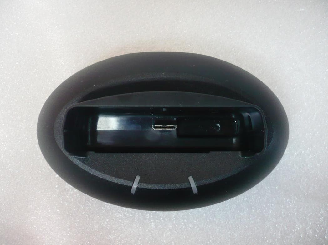
RNGM1503RFX
Jul 17, 2011ReFlex Telemetry Device
Equipment Class
JBP - Part 15 Class B Computing Device Peripheral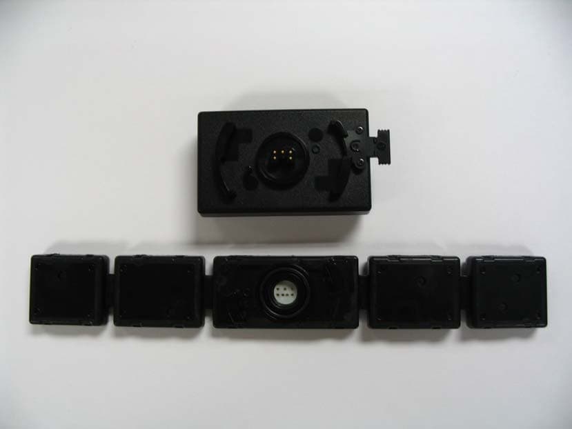
RNGPT100RX
Jul 17, 2007ReFlex Telemetry Device
Equipment Class
PCB - PCS Licensed Transmitter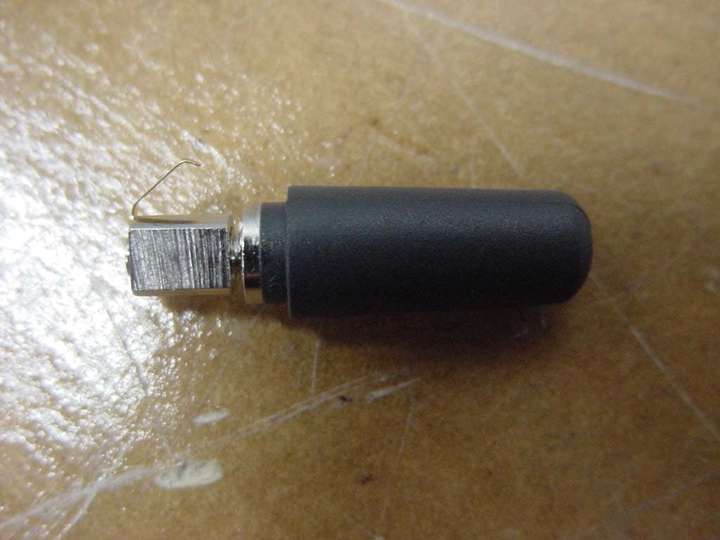
RNGM900RFX
Jan 29, 2006ReFlex Telemetry Device
Equipment Class
PCB - PCS Licensed Transmitter