Text extracted from the exhibit documents filed with the FCC. Open a document above to read the original.
15.214(d) Statement The DSS02 maintains wireless security and prevents electronic eavesdropping through multiple techniques. In addition to the difficult nature of decoding the spread spectrum signal a 24-bit security code resulting in over 16-million combinations is used between the handset and base. The ID is combined with control channel scrambling codes making it unmanageable for an eavesdropper to recover the signal to a usable form. The exact method for deriving the keys is considered proprietary.
Display messages The calling party is blocking name and number information. Your local phone company is unable to receive information about the callerβs name and number. You have received a new voice message in your Voice Mail service. The total number of new calls received. There is another phone off hook and in use utilizing the same phone line, or the telephone line cord is not connected to the base. Find handset To locate the handset, press the FIND key on the base. The handset will beep and FIND will appear on the display. When the handset is located, press the END key to cancel paging or press the END key on the base to cancel. If you receive an incoming call, FIND is cancelled. Cordless Phone Basics Date and time When not showing Caller ID information, the current date and time will appear on the display. There is no need to enter the date and time as it is transmitted automatically when Caller ID data is sent from your local phone company. (After receiving the first call, the current date and time will be entered and will automatically appear on the display.) Directory The phone book directory allows you to look up and dial a number previously stored in memory. Your phone stores up to 30 names and numbers that can be searched alphabetically and stored from Caller ID records. Storing from a Caller ID record 1.Using the ARROW keys (< or >), select a Caller ID record you would like to store in the directory. 2.Press the DIRECTORY key, and the display will show COPY and SEARCH options. Press the ARROW keys to toggle the arrow to either COPY the Caller ID record into the directory or SEARCH for a name previously stored in memory. See Figure N. 3. When the arrow is pointing to COPY, press the DIAL key. The display will show COPIED indicating the record was stored into memory. Adding a name and number 1.Press the DIRECTORY key. The display will show SEARCH and ADD options. Press the ARROW keys to toggle the arrow to either SEARCH for a name previously stored in memory or ADD a new name and phone number. 2.Enter the 10-digit Voice Mail access number (area code + phone number) you dial to retrieve your Voice Mail messages. If you would like to automatically enter your PIN code, press the REDIAL key to create a PAUSE then enter your PIN. Press the DIAL button to store the number in memory. The display will read NUMBER STORED. REDIAL key = PAUSE Note: PAUSE creates a 2-second delay before playing the PIN code. It may be necessary to add additional PAUSE entries to create a longer delay for some voice mail systems. For example, entering PAUSE three times before entering your PIN code will create a six-second pause. 3.To change your Voice Mail access number previously stored in memory, press the OPTIONS button and select MESSAGE BUTTON. The number currently programmed will be displayed. To change, press DIAL and enter a new number. To store, Press DIAL again. The display will show NUMBER STORED. Once the number is stored, simply press the MESSAGE button. The phone will automatically dial your Voice Mail access number. Step 1: Select the best location For the best reception, place the base in a high central location, away from other electrical devices such as a TV, personal computer, microwave or other cordless phones. Step 2: Install and charge the handset battery Before using the phone, you must first charge the battery pack continuously for at least 15 hours. 1.Remove the battery door cover on the telephone handset. See Figure A. 2.Connect the battery pack to the handset using the correct polarity. The plastic connector fits together in only one way. When you are certain the connector is inserted properly, insert the battery pack into the battery compartment. See Figure B. 3.Replace the battery door cover. 4.Place the handset in the charging cradle with the keypad facing up. Aero 2000 Cordless Phone Congratulations on purchasing your Aero 2000 cordless phone from Verizon. This product has been designed to provide a clear and crisp calling experience. It incorporates features that make phone company services like Caller ID, Call Waiting and Voice Mail easier to use. Start using your Aero 2000 quickly by reading the Getting Started section on the next page. Be sure to charge the battery for a minimum of 15 hours prior to the first use. This will insure a full battery charge and long battery life. Getting Started Telephone overview Check your package contents Select the best location Install and charge the handset battery Connect base to AC power Connect base to phone line Select the language Select dialing rule Select Tone/Pulse dialing mode Program your Voice Mail access number Cordless Phone Basics Adjusting handset volume Adjusting the ringer volume Belt clip installation Headset installation Making and receiving calls Range indicator Traveling out of range Flash key Message key Options key Handset and base speakerphone Redial key Caller ID service Arrow keys Delete key Dial key New call and message waiting light Display messages Find handset Date and time Directory Using network calling features Useful Information Pre-programmed calling features Battery replacement Troubleshooting tips Maintenance Hearing aid compatibility General information FCC information Limited warranty Industry Canada information Safety information Aero 2000 Cordless Phone Getting StartedGetting Started Features: Direct Band Digital Spread Spectrum Technology Call Waiting Caller ID* Dual keypad on base and handset Dual backlit display on base and handset Signal strength indicator Phone book directory One touch Voice Mail access key* New call indicator light Voice Mail message indicator light* Long lasting NiMH battery English/Spanish language option Headset jack 10-hour talk time 20-day standby time Redial Tone/Pulse dialing Hearing aid compatible *You must subscribe to service from your local telephone company. Step 5: Select the language (English or Spanish) The Language option can be used to select English or Spβ¦
Text truncated - open the document above for the full version.
DSS02 BLOCK DIAGRAM CLOCKS AND RF [HANDSET AND BASE ] RADIOASIC CODEC 19.2MHz 9.6MHz Reference Clock (sine wave) Synthesizer Clock 1.2 MHz Synthesizer Data 1.2 MHz RXIP 300kHz TX DATA 300kHz RXIN 300kHz RXQP 300kHz RXQN 300kHz NOTE: All clocks are square waves unless otherwise noted. 902MHz to 928MHz Spread Sprectrum 4 . 8 M H z M a s t e r c l o c k 1 . 2 M H z c l o c k S e r i a l D a t a 1 . 2 M H z S e r i a l D a t a 1 . 2 M H z Signals above 1 MHz
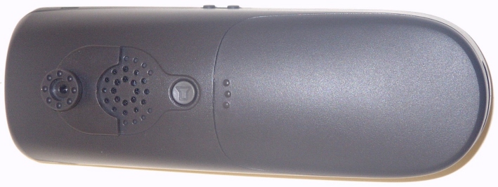
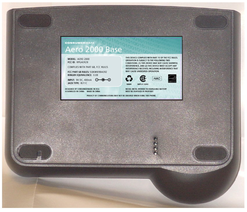
DSS02 BASE SIDES BOTTOM EDGE LEFT EDGE RIGHT EDGE TOP EDGE
BASE RADIO PCB COMPONENT SIDE
HANDSET RADIO PCB SOLDER SIDE
Page 1 of 111 Report No: FC03-043A ADDENDUM TO FC03-043 FOR THE 900 MHZ CORDLESS TELEPHONE, AERO 2000 FCC PART 15 SUBPART C SECTION 15.247 & CISPR 22 (1997) CLASS B COMPLIANCE DATE OF ISSUE: FEBRUARY 27, 2004 PREPARED FOR: Consumerware, Inc. 11730 118th Ave. NE, Ste A 300 Kirkland, WA 98034 PREPARED BY: Joyce Walker CKC Laboratories, Inc. 5473A Clouds Rest Mariposa, CA 95338 P.O. No.: W.O. No.: CW0307011 79460 Date of test:October 9, 2003 β February 26, 2004 Report No.: FC03-043A This report contains a total of 111 pages and may be reproduced in full only. Partial reproduction may only be done with the written consent of CKC Laboratories, Inc. The results in this report apply only to the items tested, as identified herein. Page 2 of 111 Report No: FC03-043A TABLE OF CONTENTS Administrative Information.................................................................................................4 Summary of Results............................................................................................................5 Conditions for Compliance..................................................................................................5 Approvals...........................................................................................................................5 Equipment Under Test (EUT) Description............................................................................6 FCC 15.31(e) Voltage Variation..........................................................................................6 FCC 15.31(m) Number Of Channels....................................................................................6 FCC 15.33(a) Frequency Ranges Tested..............................................................................6 FCC 15.35 Analyzer Bandwidth Settings..............................................................................6 FCC 15.203 Antenna Requirements.....................................................................................7 FCC 15.205 Restricted Bands..............................................................................................7 EUT Operating Frequency...................................................................................................7 Equipment Under Test........................................................................................................7 Peripheral Devices..............................................................................................................7 Measurement Uncertainty....................................................................................................7 Report of Measurements.....................................................................................................8 FCC 15.247(a)(2) Occupied Bandwidth - Base Station..............................................8 FCC 15.247(b)(3) Peak Output: Base Station............................................................11 FCC 15.247(b)(4) Directional Gain Reduction: Base Station.....................................11 FCC 15.247(c) Band Edge - Base Station.................................................................12 FCC 15.247(c) Six Highest Radiated Emission Levels: Base Station & Handset, 9kHz-30MHz..16 FCC 15.247(c) Six Highest Radiated Emission Levels: Base Station, 30-1000MHz.....17 FCC 15.247(c) Six Highest Radiated Emission Levels: Base Station, 1-10GHz...........18 FCC 15.247(d) Power Spectral Density Density-Base Station....................................19 FCC 2.1093 Maximum Permissible Exposure Calculations β Base Station..................22 FCC 15.247(a)(2) Occupied Bandwidth - Handset....................................................23 FCC 15.247(b)(3) Peak Output: Handset.................................................................26 FCC 15.247(b)(4) Directional Gain Reduction: Handset............................................26 FCC 15.247(c) Band Edge - Handset.......................................................................27 FCC 15.247(c) Six Highest Radiated Emission Levels: Handset, 30-1000MHz...........31 FCC 15.247(c) Six Highest Radiated Emission Levels: Handset, 1-10GHz.................32 FCC 15.247(d) Power Spectral Density Density-Handset..........................................33 FCC 2.1093 Maximum Permissible Exposure Calculations -Handset.........................36 CISPR 22 Six Highest Conducted Emission Levels: Base Station & Handset.............37 Temperature And Humidity During Testing..........................................................................38 EUT Setup.........................................................................................................................38 Correction Factors..............................................................................................................38 Table A: Sample Calculations..................................................................................38 Test Instrumentation and Analyzer Settings..........................................................................39 Spectrum Analyzer Detector Functions....................................................................39 Peak..........................................................................................................39 Quasi-Peak.................................................................................................39 Average.....................................................................................................39 EUT Testing.......................................................................................................................40 Mains Conducted Emissions....................................................................................40 Page 3 of 111 Report No: FC03-043A Antenna Conducted Emissions.................................................................................40 Radiated Emissions.........................................................................β¦
Text truncated - open the document above for the full version.
BASE STATION - PHOTOGRAPH SHOWING OCCUPIED BANDWIDTH BASE STATATION - PHOTOGRAPH SHOWING PEAK OUTPUT POWER BASE STATION - PHOTOGRAPH SHOWING LF RADIATED SPURIOUS EMISSIONS BASE STATATION - PHOTOGRAPH SHOWING HF RADIATED SPURIOUS EMISSIONS BASE STATION - PHOTOGRAPH SHOWING BAND EDGE BASE STATION - PHOTOGRAPH SHOWING POWER SPECTRAL DENSITY BASE STATION - PHOTOGRAPH SHOWING MAINS CONDUCTED EMISSIONS
5473A Clouds Rest Β· Mariposa, California Β· United States
| # | Rule Parts | Frequency Range | Power Output |
|---|---|---|---|
| 1 | 15C | 904.2 MHz - 926.02 MHz | 194.00 mW |

900 MHz Cordless Telephone Handset
Equipment Class
DTS - Digital Transmission System