FCCID.CO- FCC ID Database
HomeCompaniesEquipment ClassesSearch

© 2026 FCC ID Database. All rights reserved.

AboutContactData sourced from FCC public records
  1. Home/
  2. Consumerware Incorporated/
  3. RPGAER2H

RPGAER2H900 MHz Cordless Telephone Handset

Consumerware Incorporated
900 MHz Cordless Telephone Handset - FCC ID RPGAER2H - Consumerware Incorporated
Click to zoom

Application Details

Equipment Class
DTS - Digital Transmission System
Date of Grant
Mar 03, 2004
Application Purpose
Original Equipment
Date of Application
Mar 03, 2004
Equipment Note
900 MHz Cordless Telephone Handset
Frequency Range
904.20000000 - 926.20000000
Company
Consumerware Incorporated
Country
United States

Documents & Files

Select a file to view

Users Manual

↗
↗
↗
↗
↗

Block Diagram

↗

Cover Letter(s)

↗

External Photos

↗
↗
↗

ID Label/Location Info

↗
↗

Internal Photos

↗
↗
↗
↗

Operational Description

↗

RF Exposure Info

↗

Test Report

↗

Test Setup Photos

↗

Document Text

Text extracted from the exhibit documents filed with the FCC. Open a document above to read the original.

Users Manual

15.214(d) Statement The DSS02 maintains wireless security and prevents electronic eavesdropping through multiple techniques. In addition to the difficult nature of decoding the spread spectrum signal a 24-bit security code resulting in over 16-million combinations is used between the handset and base. The ID is combined with control channel scrambling codes making it unmanageable for an eavesdropper to recover the signal to a usable form. The exact method for deriving the keys is considered proprietary.

Users Manual

Warning! Changes or modifications to this unit not expressly approved by Consumerware could void the FCC authority to operate this equipment. This includes the addition of any external antenna device. To comply with FCC regulations, the following conditions must be met: This device complies with Part 68 of the FCC rules The label on the bottom of this device contains the FCC registration number and ringer equivalence number. If requested by the telephone company, the FCC registration number of this device and the ringer equivalence number must be reported. For reliable operation, the sum of the ringer equivalence numbers for devices connected to a single telephone line should not exceed five. This device must not be installed on coin operated telephone lines or party lines. This device complies with Part 15 of the FCC rules Operation is subject to the following two conditions: 1. This device may not cause harmful interference. 2. This device must accept any interference received, including interference that may cause undesired operation. These limits are designed to provide reasonable protection against harmful interference in a residential installation. Rights of the telephone company The FCC has granted the telephone company the right to disconnect service in the event that your phone causes problems on the telephone line. In addition, the telephone company may make changes in facilities and services which may affect the operation of your unit. Your telephone company must give adequate notice in writing prior to such actions to allow you time for making necessary arrangements to continue uninterrupted service. If you are having trouble with your telephone service, you must first disconnect your phone to determine if it is the cause of your problem. If you determine that it is the cause, you must leave it disconnected until the trouble has been corrected. Radio interference Some cordless telephones operate at frequencies that may cause interference to nearby TVs and VCRs. To minimize or prevent such interference, the system base should not be placed near or on top of a TV or VCR. Moving the base farther away from the TV or VCR will often reduce or eliminate the interference. There is no guarantee that interference will not occur in a particular installation. If this telephone does not cause harmful interference to radio or television reception, which can be determined by turning the system off an on, the user is encouraged to try to correct the interference by one or more of the following measures: 1. Increase the separation between base station and receiver. 2. Connect the base station into an outlet on a circuit different from that to which the receiver is connected. 3. Consult the dealer or an experienced radio/TV technician for help. Repair work on this device must be done by Consumerware, Inc. or an authorized repair station. FCC Radiation Exposure Statement This equipment complies with FCC radiation exposure limits set forth for an uncontrolled environment and should be installed and operated with a minimum separation distance of 1.18 cm from the back of the phone and the user’s body. Important: Evidence of original purchase is required for warranty service Warranty Term This limited, non-transferable warranty is provided to the original purchaser. The product is warranted to be free from defects in materials and workmanship under normal installation, use and service for a period of one (1) year from the date of purchase as shown on the purchaser’s receipt. If the unit should prove defective within the warranty period, please call the Consumerware Customer Service Center at 1-800-456-6076 for product return information. Statement of Remedy Consumerware’s obligation under this warranty is limited to repair or replacement (at Consumeware’s option) of the product or any part(s) which are defective provided that the product is returned to Consumeware’s Customer Care during the warranty period. A copy of the purchase receipt must accompany products returned. In the absence of a purchase receipt, the warranty period shall be one (1) year from the date of manufacture. Repair or replacement of the product is your sole and exclusive remedy. If the product is repaired, reconditioned component parts or materials may be used. If the product is replaced, Consumerware may chose to replace it with a new or reconditioned product of the same or similar design. The repaired or replacement product will be warranted for either (a) 90 days or (b) the remainder of the original one (1) year warranty period, whichever is longer. Batteries are warranted to be free from defects at the time of purchase. FCC InformationLimited Warranty Useful Information(continued) 3031

Users Manual

Display messages The calling party is blocking name and number information. Your local phone company is unable to receive information about the caller’s name and number. You have received a new voice message in your Voice Mail service. The total number of new calls received. There is another phone off hook and in use utilizing the same phone line, or the telephone line cord is not connected to the base. Find handset To locate the handset, press the FIND key on the base. The handset will beep and FIND will appear on the display. When the handset is located, press the END key to cancel paging or press the END key on the base to cancel. If you receive an incoming call, FIND is cancelled. Cordless Phone Basics Date and time When not showing Caller ID information, the current date and time will appear on the display. There is no need to enter the date and time as it is transmitted automatically when Caller ID data is sent from your local phone company. (After receiving the first call, the current date and time will be entered and will automatically appear on the display.) Directory The phone book directory allows you to look up and dial a number previously stored in memory. Your phone stores up to 30 names and numbers that can be searched alphabetically and stored from Caller ID records. Storing from a Caller ID record 1.Using the ARROW keys (< or >), select a Caller ID record you would like to store in the directory. 2.Press the DIRECTORY key, and the display will show COPY and SEARCH options. Press the ARROW keys to toggle the arrow to either COPY the Caller ID record into the directory or SEARCH for a name previously stored in memory. See Figure N. 3. When the arrow is pointing to COPY, press the DIAL key. The display will show COPIED indicating the record was stored into memory. Adding a name and number 1.Press the DIRECTORY key. The display will show SEARCH and ADD options. Press the ARROW keys to toggle the arrow to either SEARCH for a name previously stored in memory or ADD a new name and phone number. 2.Enter the 10-digit Voice Mail access number (area code + phone number) you dial to retrieve your Voice Mail messages. If you would like to automatically enter your PIN code, press the REDIAL key to create a PAUSE then enter your PIN. Press the DIAL button to store the number in memory. The display will read NUMBER STORED. REDIAL key = PAUSE Note: PAUSE creates a 2-second delay before playing the PIN code. It may be necessary to add additional PAUSE entries to create a longer delay for some voice mail systems. For example, entering PAUSE three times before entering your PIN code will create a six-second pause. 3.To change your Voice Mail access number previously stored in memory, press the OPTIONS button and select MESSAGE BUTTON. The number currently programmed will be displayed. To change, press DIAL and enter a new number. To store, Press DIAL again. The display will show NUMBER STORED. Once the number is stored, simply press the MESSAGE button. The phone will automatically dial your Voice Mail access number. Step 1: Select the best location For the best reception, place the base in a high central location, away from other electrical devices such as a TV, personal computer, microwave or other cordless phones. Step 2: Install and charge the handset battery Before using the phone, you must first charge the battery pack continuously for at least 15 hours. 1.Remove the battery door cover on the telephone handset. See Figure A. 2.Connect the battery pack to the handset using the correct polarity. The plastic connector fits together in only one way. When you are certain the connector is inserted properly, insert the battery pack into the battery compartment. See Figure B. 3.Replace the battery door cover. 4.Place the handset in the charging cradle with the keypad facing up. Aero 2000 Cordless Phone Congratulations on purchasing your Aero 2000 cordless phone from Verizon. This product has been designed to provide a clear and crisp calling experience. It incorporates features that make phone company services like Caller ID, Call Waiting and Voice Mail easier to use. Start using your Aero 2000 quickly by reading the Getting Started section on the next page. Be sure to charge the battery for a minimum of 15 hours prior to the first use. This will insure a full battery charge and long battery life. Getting Started Telephone overview Check your package contents Select the best location Install and charge the handset battery Connect base to AC power Connect base to phone line Select the language Select dialing rule Select Tone/Pulse dialing mode Program your Voice Mail access number Cordless Phone Basics Adjusting handset volume Adjusting the ringer volume Belt clip installation Headset installation Making and receiving calls Range indicator Traveling out of range Flash key Message key Options key Handset and base speakerphone Redial key Caller ID service Arrow keys Delete key Dial key New call and message waiting light Display messages Find handset Date and time Directory Using network calling features Useful Information Pre-programmed calling features Battery replacement Troubleshooting tips Maintenance Hearing aid compatibility General information FCC information Limited warranty Industry Canada information Safety information Aero 2000 Cordless Phone Getting StartedGetting Started Features: Direct Band Digital Spread Spectrum Technology Call Waiting Caller ID* Dual keypad on base and handset Dual backlit display on base and handset Signal strength indicator Phone book directory One touch Voice Mail access key* New call indicator light Voice Mail message indicator light* Long lasting NiMH battery English/Spanish language option Headset jack 10-hour talk time 20-day standby time Redial Tone/Pulse dialing Hearing aid compatible *You must subscribe to service from your local telephone company. Step 5: Select the language (English or Spanish) The Language option can be used to select English or Sp…

Text truncated - open the document above for the full version.

Users Manual

Display messages The calling party is blocking name and number information. Your local phone company is unable to receive information about the caller’s name and number. You have received a new voice message in your Voice Mail service. The total number of new calls received. There is another phone off hook and in use utilizing the same phone line, or the telephone line cord is not connected to the base. Find handset To locate the handset, press the FIND key on the base. The handset will beep and FIND will appear on the display. When the handset is located, press the END key to cancel paging or press the END key on the base to cancel. If you receive an incoming call, FIND is cancelled. Cordless Phone Basics Date and time When not showing Caller ID information, the current date and time will appear on the display. There is no need to enter the date and time as it is transmitted automatically when Caller ID data is sent from your local phone company. (After receiving the first call, the current date and time will be entered and will automatically appear on the display.) Directory The phone book directory allows you to look up and dial a number previously stored in memory. Your phone stores up to 30 names and numbers that can be searched alphabetically and stored from Caller ID records. Storing from a Caller ID record 1.Using the ARROW keys (< or >), select a Caller ID record you would like to store in the directory. 2.Press the DIRECTORY key, and the display will show COPY and SEARCH options. Press the ARROW keys to toggle the arrow to either COPY the Caller ID record into the directory or SEARCH for a name previously stored in memory. See Figure N. 3. When the arrow is pointing to COPY, press the DIAL key. The display will show COPIED indicating the record was stored into memory. Adding a name and number 1.Press the DIRECTORY key. The display will show SEARCH and ADD options. Press the ARROW keys to toggle the arrow to either SEARCH for a name previously stored in memory or ADD a new name and phone number. 2.Enter the 10-digit Voice Mail access number (area code + phone number) you dial to retrieve your Voice Mail messages. If you would like to automatically enter your PIN code, press the REDIAL key to create a PAUSE then enter your PIN. Press the DIAL button to store the number in memory. The display will read NUMBER STORED. REDIAL key = PAUSE Note: PAUSE creates a 2-second delay before playing the PIN code. It may be necessary to add additional PAUSE entries to create a longer delay for some voice mail systems. For example, entering PAUSE three times before entering your PIN code will create a six-second pause. 3.To change your Voice Mail access number previously stored in memory, press the OPTIONS button and select MESSAGE BUTTON. The number currently programmed will be displayed. To change, press DIAL and enter a new number. To store, Press DIAL again. The display will show NUMBER STORED. Once the number is stored, simply press the MESSAGE button. The phone will automatically dial your Voice Mail access number. Step 1: Select the best location For the best reception, place the base in a high central location, away from other electrical devices such as a TV, personal computer, microwave or other cordless phones. Step 2: Install and charge the handset battery Before using the phone, you must first charge the battery pack continuously for at least 15 hours. 1.Remove the battery door cover on the telephone handset. See Figure A. 2.Connect the battery pack to the handset using the correct polarity. The plastic connector fits together in only one way. When you are certain the connector is inserted properly, insert the battery pack into the battery compartment. See Figure B. 3.Replace the battery door cover. 4.Place the handset in the charging cradle with the keypad facing up. Aero 2000 Cordless Phone Congratulations on purchasing your Aero 2000 cordless phone from Verizon. This product has been designed to provide a clear and crisp calling experience. It incorporates features that make phone company services like Caller ID, Call Waiting and Voice Mail easier to use. Start using your Aero 2000 quickly by reading the Getting Started section on the next page. Be sure to charge the battery for a minimum of 15 hours prior to the first use. This will insure a full battery charge and long battery life. Getting Started Telephone overview Check your package contents Select the best location Install and charge the handset battery Connect base to AC power Connect base to phone line Select the language Select dialing rule Select Tone/Pulse dialing mode Program your Voice Mail access number Cordless Phone Basics Adjusting handset volume Adjusting the ringer volume Belt clip installation Headset installation Making and receiving calls Range indicator Traveling out of range Flash key Message key Options key Handset and base speakerphone Redial key Caller ID service Arrow keys Delete key Dial key New call and message waiting light Display messages Find handset Date and time Directory Using network calling features Useful Information Pre-programmed calling features Battery replacement Troubleshooting tips Maintenance Hearing aid compatibility General information FCC information Limited warranty Industry Canada information Safety information Aero 2000 Cordless Phone Getting StartedGetting Started Features: Direct Band Digital Spread Spectrum Technology Call Waiting Caller ID* Dual keypad on base and handset Dual backlit display on base and handset Signal strength indicator Phone book directory One touch Voice Mail access key* New call indicator light Voice Mail message indicator light* Long lasting NiMH battery English/Spanish language option Headset jack 10-hour talk time 20-day standby time Redial Tone/Pulse dialing Hearing aid compatible *You must subscribe to service from your local telephone company. Step 5: Select the language (English or Spanish) The Language option can be used to select English or Sp…

Text truncated - open the document above for the full version.

Block Diagram

DSS02 BLOCK DIAGRAM CLOCKS AND RF [HANDSET AND BASE ] RADIOASIC CODEC 19.2MHz 9.6MHz Reference Clock (sine wave) Synthesizer Clock 1.2 MHz Synthesizer Data 1.2 MHz RXIP 300kHz TX DATA 300kHz RXIN 300kHz RXQP 300kHz RXQN 300kHz NOTE: All clocks are square waves unless otherwise noted. 902MHz to 928MHz Spread Sprectrum 4 . 8 M H z M a s t e r c l o c k 1 . 2 M H z c l o c k S e r i a l D a t a 1 . 2 M H z S e r i a l D a t a 1 . 2 M H z Signals above 1 MHz

External Photos

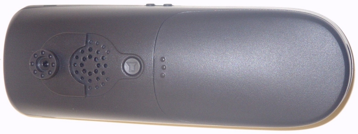
DSS02 HANDSET BACK

External Photos

HANDSET SIDES TOP LEFT SIDE RIGHT SIDE BOTTOM

ID Label/Location Info

AERO 2000 NICKEL METAL HYDRIDE RECHARGEABLE BATTERY MUST BE DISPOSED OF PROPERLY. CAUTION: FIRE RISK, USE ONLY CONSUMERWARE NM1500 REPLACEMENT BATTERY. NiMH www.cwbattery.com 1-800-456-6076 FCC ID: RPGAER2H PRIVACY OF COMMUNICATIONS MAY NOT BE ENSURED WHEN USING THIS PHONE.

ID Label/Location Info

COVER AND BATTERY REMOVED DSS02 HANDSET BACK

Internal Photos

BASE RADIO PCB COMPONENT SIDE

Internal Photos

DSS02 HANDSET BACK BATTERY COVER REMOVED

Internal Photos

HANDSET RADIO PCB SOLDER SIDE

Operational Description

Operational Description The DSS02 uses direct-sequence spread spectrum IQ modulation in the ISM band 902-928MHz. A time division duplexing rate of 1ms is used to switch between handset and base RX/TX frames. The RF output path starts at the baseband ASIC which is connected directly to the RF105 transceiver. The transmit path from the RF105 is a variable gain direct conversion modulator. The single ended output of the modulator in connected via a 33pF capacitor to the RF106 29dB gain PA. The PA is then capacitively connected through a transmit/receive (TR) switch to the antenna. The receive path starts at the antenna and is connected again through the TR switch and a ceramic bandpass filter to the RF105. The RF105 provides complete RF-to-baseband in-phase quadrature demodulation through a LNA, double-balanced quadrature mixer, channel selection filter, and baseband variable-gain amplifier. This output is then directly connected back to the input of the baseband ASIC.

RF Exposure Info

FCC 2.1093 MAXIMUM PERMISSIBLE EXPOSURE CALCULATIONS - HANDSET Calculations prepared for: Consumerware, Inc. 11730 118 th Ave. NE, STE A 300 Kirklan, WA 98034 Calculations prepared by: Andrew Pace 14797 NE 95 th ST Redmond, WA 98052 Model Number: Aero 2000 FCC Identification: Pending Fundamental Operating Frequency: 902-928 MHz Measured Maximum Output Power: 0.014 Watts (11.4 dBm) (OATS, 916.5 MHz) MPE limit in accordance with FCC part 1.1311, table 1 EIRP = Maximum Measured Output Power (dBm) + Antenna Gain (dBi) EIRP = 11.4 dBm + 1 dBi = 12.4 dBm (17 mWatt) Limit for Maximum permissible exposure: (B) Limit for General population/uncontrolled Exposure: For the frequency range of 1500-100,000 MHz , the MPE is 1 (mW/cm 2 ) EIRP (mW) Distance (cm) Power Density (mW/cm 2 ) Result 17.38 1.18 1.000 Pass Power Density (mW/cm 2 ) = EIRP 4*pi*d^2 EIRP is given in mW Distance (d) is given in centimeters Under normal operating conditions, the antenna is designed to maintain a separation distance of 3 cm from all persons. As shown in the MPE results above, this device passes the limits specified in 1.1311 at a distance of 3 cm and at the rated output power of 0.200 Watts. For the measured output power at the antenna terminal of 0.014 Watts, the EUT satisfies the requirement in the 1500 to 100000 MHz frequency range.

Test Report

Page 1 of 111 Report No: FC03-043A ADDENDUM TO FC03-043 FOR THE 900 MHZ CORDLESS TELEPHONE, AERO 2000 FCC PART 15 SUBPART C SECTION 15.247 & CISPR 22 (1997) CLASS B COMPLIANCE DATE OF ISSUE: FEBRUARY 27, 2004 PREPARED FOR: Consumerware, Inc. 11730 118th Ave. NE, Ste A 300 Kirkland, WA 98034 PREPARED BY: Joyce Walker CKC Laboratories, Inc. 5473A Clouds Rest Mariposa, CA 95338 P.O. No.: W.O. No.: CW0307011 79460 Date of test:October 9, 2003 – February 26, 2004 Report No.: FC03-043A This report contains a total of 111 pages and may be reproduced in full only. Partial reproduction may only be done with the written consent of CKC Laboratories, Inc. The results in this report apply only to the items tested, as identified herein. Page 2 of 111 Report No: FC03-043A TABLE OF CONTENTS Administrative Information.................................................................................................4 Summary of Results............................................................................................................5 Conditions for Compliance..................................................................................................5 Approvals...........................................................................................................................5 Equipment Under Test (EUT) Description............................................................................6 FCC 15.31(e) Voltage Variation..........................................................................................6 FCC 15.31(m) Number Of Channels....................................................................................6 FCC 15.33(a) Frequency Ranges Tested..............................................................................6 FCC 15.35 Analyzer Bandwidth Settings..............................................................................6 FCC 15.203 Antenna Requirements.....................................................................................7 FCC 15.205 Restricted Bands..............................................................................................7 EUT Operating Frequency...................................................................................................7 Equipment Under Test........................................................................................................7 Peripheral Devices..............................................................................................................7 Measurement Uncertainty....................................................................................................7 Report of Measurements.....................................................................................................8 FCC 15.247(a)(2) Occupied Bandwidth - Base Station..............................................8 FCC 15.247(b)(3) Peak Output: Base Station............................................................11 FCC 15.247(b)(4) Directional Gain Reduction: Base Station.....................................11 FCC 15.247(c) Band Edge - Base Station.................................................................12 FCC 15.247(c) Six Highest Radiated Emission Levels: Base Station & Handset, 9kHz-30MHz..16 FCC 15.247(c) Six Highest Radiated Emission Levels: Base Station, 30-1000MHz.....17 FCC 15.247(c) Six Highest Radiated Emission Levels: Base Station, 1-10GHz...........18 FCC 15.247(d) Power Spectral Density Density-Base Station....................................19 FCC 2.1093 Maximum Permissible Exposure Calculations – Base Station..................22 FCC 15.247(a)(2) Occupied Bandwidth - Handset....................................................23 FCC 15.247(b)(3) Peak Output: Handset.................................................................26 FCC 15.247(b)(4) Directional Gain Reduction: Handset............................................26 FCC 15.247(c) Band Edge - Handset.......................................................................27 FCC 15.247(c) Six Highest Radiated Emission Levels: Handset, 30-1000MHz...........31 FCC 15.247(c) Six Highest Radiated Emission Levels: Handset, 1-10GHz.................32 FCC 15.247(d) Power Spectral Density Density-Handset..........................................33 FCC 2.1093 Maximum Permissible Exposure Calculations -Handset.........................36 CISPR 22 Six Highest Conducted Emission Levels: Base Station & Handset.............37 Temperature And Humidity During Testing..........................................................................38 EUT Setup.........................................................................................................................38 Correction Factors..............................................................................................................38 Table A: Sample Calculations..................................................................................38 Test Instrumentation and Analyzer Settings..........................................................................39 Spectrum Analyzer Detector Functions....................................................................39 Peak..........................................................................................................39 Quasi-Peak.................................................................................................39 Average.....................................................................................................39 EUT Testing.......................................................................................................................40 Mains Conducted Emissions....................................................................................40 Page 3 of 111 Report No: FC03-043A Antenna Conducted Emissions.................................................................................40 Radiated Emissions.........................................................................…

Text truncated - open the document above for the full version.

Test Setup Photos

HANDSET - PHOTOGRAPH SHOWING OCCUPIED BANDWIDTH HANDSET - PHOTOGRAPH SHOWING PEAK OUTPUT POWER HANDSET - PHOTOGRAPH SHOWING LF RADIATED SPURIOUS EMISSIONS HANDSET - PHOTOGRAPH SHOWING HF RADIATED SPURIOUS EMISSIONS HANDSET - PHOTOGRAPH SHOWING BAND EDGE HANDSET - PHOTOGRAPH SHOWING POWER SPECTRAL DENSITY HANDSET - PHOTOGRAPH SHOWING MAINS CONDUCTED EMISSIONS

Contact Information

Applicant

Mark Gosselin(CTO)
[email protected](425)820-1431Fax: (425)820-0739

Technical Contact

CKC Laboratories, Inc.Mary Ellen Clayton
[email protected]209-966-5240

5437-A Clouds Rest · Mairposa, California · United States

Non-Technical Contact

CKC Laboratories, Inc.Mary Ellen Clayton
[email protected]209-966-5240

Test Firm

CKC Laboratories, Inc.Steve Behm
[email protected]209-966-5240Fax: 866 779 9776

Technical Specifications

#Rule PartsFrequency RangePower Output
115C904.2 MHz - 926.2 MHz14.00 mW
Confidentiality
Long Term
Grant Notes
Power listed is EIRP. End users must be provided with antenna installation instructions and transmitter operating conditions for satisfying RF exposure compliance.

Other Applications from Consumerware Incorporated
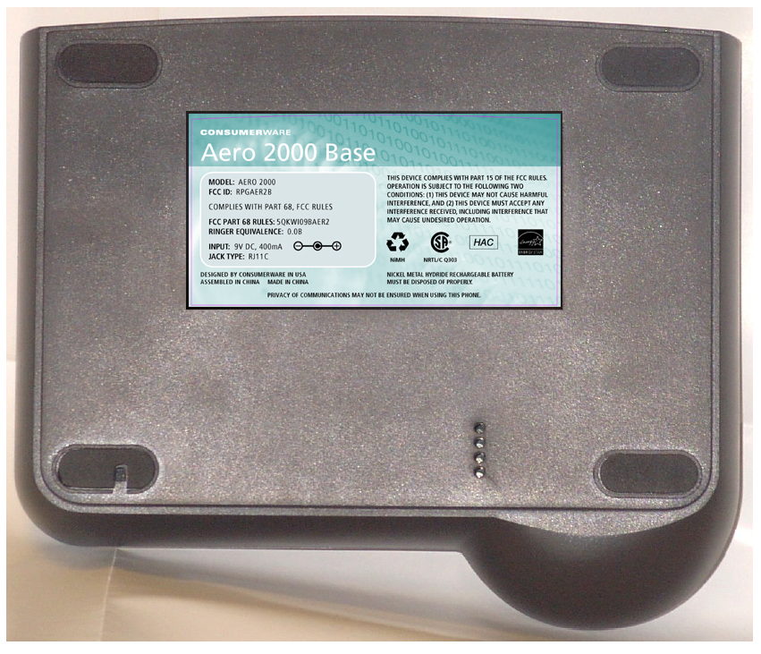
900 MHz Cordless Telephone Base - FCC ID RPGAER2B - Consumerware Incorporated
RPGAER2B

900 MHz Cordless Telephone Base

Mar 03, 2004

Equipment Class

DTS - Digital Transmission System