RQ2PI070H04CBTablet PC
XiangDe Electronics Technology (ShenZhen) CO., LTD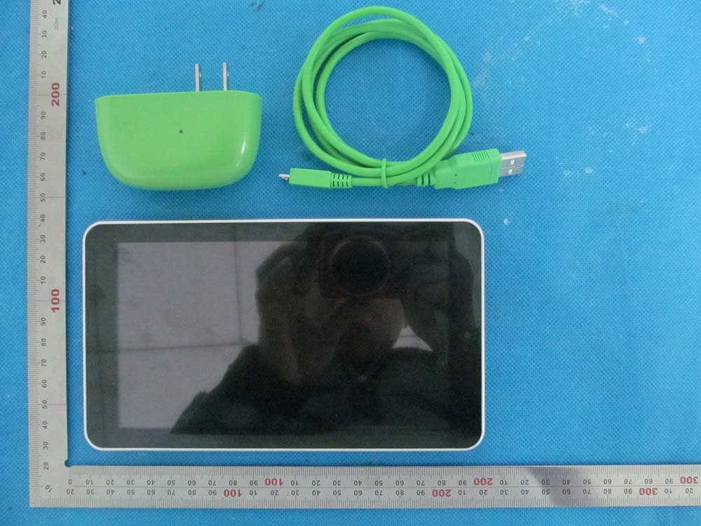
Click to zoom
Application Details
- Equipment Class
- DSS - Part 15 Spread Spectrum Transmitter
- Date of Grant
- May 05, 2014
- Application Purpose
- Original Equipment
- Date of Application
- May 05, 2014
- Equipment Note
- Tablet PC
- Frequency Range
- 2402.00000000 - 2480.00000000
- Country
- China
Documents & Files
Document Text
Text extracted from the exhibit documents filed with the FCC. Open a document above to read the original.
Users Manual
Ta b l e t P C Users Manual Brand name:Vivitar Model name:PI070H04CB FCC ID:RQ2PI070H04CB This manual is specially formulated for the users first using this MID with the purpose of providing the information about basic operations and important functions. 1 Appearance Description Function Description of Keys and Interfaces Volume+/Volume-: Short press the button to turn up/down the volume. Power Key:Long press it for 5 seconds to startup/shutdown; short press to lock the screen, and wake it up by short press again. Charge/USB interface: Used for connecting the computer, data transmission devices and external devices, such as mouse, USB flash disks, and OTG wires. At the same time, this interface is also the charger Front-facingCam era Vo l u m e + Vo l u m e _ - PowerKey Rear Camera TF Card Slot Loud Speaker EarphoneAperture Microphone HDMI Micro USB 2 interface. TF Card Slot: Externally connect the TF card. Basic Operations Startup/Shutdown In status of power-off, after long press the power key for 5 seconds, it will enter into the main screen after displaying the startup picture. In status of power-on, after long press the power key for 5 seconds, it will pop up the dialogue box, and select “OK” key to shutdown, and the “Cancel” key to keep the power-on state. PC Connection In status of power-on, after connecting with the computer using USB, select the connection method of “Media Transfer Protocol (MTP)” to achieve the removable disk function, which can upload and download data such as documents, etc. Notes: MTP is a part of Windows Media framework, therefore it closely connect with Windows Media Play. Supporting technology has been embedded in 3 Windows Vista, Windows 7 and the above versions, while Windows Media Play 10 or the above version need to be installed in Windows XP if need to support MTP. There are MTP-support software packages in Mac and Linux. Charging Please timely charge the MID when prompting the low-battery on the screen. Please use the charger provided by the manufacturer to charge. Charging can be conducted in status of power-off, and the whole charging process needs about 3.5 hours. (When in full battery, the charging indicator will light off.) Reset Function If the MID crashes or shows other abnormal problems in the process of using because of improper operation, please use the pen nib or something like to click the reset key in the reset aperture to reset the MID. Restore Factory Data Reset Settings----Factory Data Rest----Reset the MID----Erase All Data on MID Main Screen Introduction Long pressing the power key for 5 seconds, MID will enter the unlocking 4 interface after displaying the startup picture. Screen Lock: Drag the screen lock icon to the unlocking direction to unlock the screen. Then, enter into the main screen, which displays as follows: (Note: There’s not only one method to unlock the screen lock, and it can be selected through the operations: Settings----Safety----Screen Lock). Detailed Operating Instructions of Main Screen: Screens Switchover: There are several main screens installed in this MID, and the user can drag the screen right and left to view all the screens. 5 Create Shortcuts: By long pressing the applications and the widget icons for 3 seconds, the icons will be enlarged, then drag this icon to the main interface to create the shortcut. Delete Shortcuts: Long press the icon needs to be deleted on the main screen for 3 seconds, and then drag the icon to the X icon appears on the screen (see the picture below), thus the shortcut can be deleted. 6 Various touching functions are as follows: Return: Touch this icon can go back to the catalog one level up. Main Screen: Touch this icon can go back to the main screen. Multi-tasks List: Displays the application thumbnails latest operated, and the user can close a certain application to release the memory. Dragging the application thumbnails on the screen right or left can remove it from the multi-tasks list. Menu: In any interfaces, clicks the Menu icon, it will pop up the submenu, which contains many settings and other operating functions. Status Bar: Display the time, the strength or weakness of the network signal and the battery power. Click the icon in the top right corner of the main interface to enter into the application programs interface, see the picture below: 7 The application program interface displays all applications and widgets in this MID, and you can enter into the related application interface by touching any of the application icons. Widgets: Many widgets are installed in this MID, such as the calendar and Email, etc.. 8 Important Settings: WIFI network settings are as follows: Step 1: Open WIRELESS & NETWORKS. The system will automatically search the networks available. Step 2: Select the target network, and input the correct network password. And then select “Connect” to connect with WIFI networks. (Notes: If the network is not encrypted, the WIFI network will be connected by directly click “Connect”.) 9 Bluetooth Bluetooth is a short-range wireless communications technology that devices can use to exchange information over a distance of about 10 meters. The most common Bluetooth devices are headphones for making calls or listening to music, hands-free kits for cars, and other portable devices, including laptops and cell phones. Touch Settings > Bluetooth. Check Bluetooth to turn it on. You must pair your phone with a device before you can connect to it. Once you pair your phone with a device, they stay paired unless you unpair them. Your phone scans for and displays the IDs of all available Bluetooth devices in range. If the device you want to pair with isn’t in the list, make it discoverable. Language & Input Settings The user can download the input method from websites of the third party and installed into this MID through applications. The new-installed input method can be used after being chosen and clicked. Language setting: Settings----Language & Input----Languages--…
Text truncated - open the document above for the full version.
Cover Letter(s)
Apr.21, 2014 Federal Communication Commission Authorization and Evaluation Division FCC ID: RQ2PI070H04CB Re: Confidentiality Request Pursuant to Sections 0.457 and 0.459 of the Commission’s Rules, the applicant hereby requests confidential treatment of information applied this application as outlined below: 1: Block Diagram 2: Circuit Diagram 3: Operational Description 4: Parts List 5: Tune Up Procedure The above materials contain trade secrets and proprietary information not customarily released to the public. The public disclosure of these matters might be harmful to the applicant and provide unjustified benefits to its competitors. The Applicant understands that pursuant to Rules 0.457, disclosure of this Application and all accompanying documentation will not be made before the date of the Grant for this application. Sincerely, XiangDe Electronics Technology (ShenZhen) CO., LTD Contact person: Xiaobo Liu Title: Project Manager
External Photos
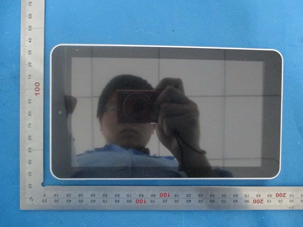
External Photos All VIEW OF EUT TOP VIEW OF EUT BOTTOM VIEW OF EUT FRONT VIEW OF EUT BACK VIEW OF EUT LEFT VIEW OF EUT RIGHT VIEW OF EUT
ID Label/Location Info
FCC ID Label Location Tablet PC Model: PI070H04CB Trade Name: Vivitar FCC ID: RQ2PI070H04CB PI070H04XA
Internal Photos
Internal Photos OPEN VIEW OF EUT BT Antenna WIFI Antenna INTERNAL VIEW OF EUT-1 INTERNAL VIEW OF EUT-2
Test Report
Report No.: AGC00892140203FE03 Page 1 of 62 FCC Test Report Report No.: AGC00892140203FE03 FCC ID : RQ2PI070H04CB APPLICATION PURPOSE : Original Equipment PRODUCT DESIGNATION : Tablet PC BRAND NAME : Vivitar MODEL NAME : PI070H04XA, PI070H04CB CLIENT : XiangDe Electronic (ShenZhen) CO.,LTD DATE OF ISSUE : Mar.15, 2014 STANDARD(S) : FCC Part 15 Rules REPORT VERSION : V1.0 Attestation of Global Compliance (Shenzhen) Co., Ltd CAUTION: This report shall not be reproduced except in full without the written permission of the test laboratory and shall not be quoted out of context. Report No.: AGC00892140203FE03 Page 2 of 62 Report Revise Record Report Version Revise Time Issued Date Valid VersionNotes V1.0 / Mar.15, 2014Valid Original Report Report No.: AGC00892140203FE03 Page 3 of 62 TABLE OF CONTENTS 1. VERIFICATION OF CONFORMITY ...................................................................................... 5 2. GENERAL INFORMATION .................................................................................................. 6 2.1. PRODUCT DESCRIPTION ........................................................................................................... 6 2.2. TABLE OF CARRIER FREQUENCYS .......................................................................................... 6 2.3. RECEIVER INPUT BANDWIDTH ................................................................................................. 7 2.4. EXAMPLE OF A HOPPING SEQUENCY IN DATA MODE ........................................................... 7 2.5. EQUALLY AVERAGE USE OF FREQUENCIES AND BEHAVIOUR ............................................ 7 2.6. RELATED SUBMITTAL(S) / GRANT (S) ....................................................................................... 8 2.7. TEST METHODOLOGY................................................................................................................ 8 2.8. SPECIAL ACCESSORIES ............................................................................................................ 8 2.9. EQUIPMENT MODIFICATIONS ................................................................................................... 8 3. MEASUREMENT UNCERTAINTY........................................................................................ 9 4. DESCRIPTION OF TEST MODES ........................................................................................ 9 5. SYSTEM TEST CONFIGURATION .................................................................................... 10 5.1. CONFIGURATION OF EUT SYSTEM ........................................................................................ 10 5.2. EQUIPMENT USED IN EUT SYSTEM ....................................................................................... 10 5.3. SUMMARY OF TEST RESULTS ................................................................................................ 10 6. TEST FACILITY .................................................................................................................. 11 7. PEAK OUTPUT POWER .................................................................................................... 12 7.1. MEASUREMENT PROCEDURE ................................................................................................ 12 7.2. TEST SET-UP (BLOCK DIAGRAM OF CONFIGURATION) ....................................................... 12 7.3. LIMITS AND MEASUREMENT RESULT .................................................................................... 13 8. 20DB BANDWIDTH ............................................................................................................ 19 8.1. MEASUREMENT PROCEDURE ................................................................................................ 19 8.2. TEST SET-UP (BLOCK DIAGRAM OF CONFIGURATION) ....................................................... 19 8.3. LIMITS AND MEASUREMENT RESULTS .................................................................................. 19 9. CONDUCTED SPURIOUS EMISSION ............................................................................... 26 9.1. MEASUREMENT PROCEDURE ................................................................................................ 26 9.2. TEST SET-UP (BLOCK DIAGRAM OF CONFIGURATION) ....................................................... 26 9.3. MEASUREMENT EQUIPMENT USED ....................................................................................... 26 9.4. LIMITS AND MEASUREMENT RESULT .................................................................................... 26 10. RADIATED EMISSION ..................................................................................................... 35 10.1. MEASUREMENT PROCEDURE .............................................................................................. 35 10.2. TEST SETUP ............................................................................................................................ 37 Report No.: AGC00892140203FE03 Page 4 of 62 10.3. TEST RESULT .......................................................................................................................... 38 11. BAND EDGE EMISSION .................................................................................................. 42 11.1. MEASUREMENT PROCEDURE .............................................................................................. 42 11.2. TEST SET-UP ........................................................................................................................... 42 11.3. TEST RESULT .......................................................................................................................... 43 12. NUMBER OF HOPPING FREQUENCY ............................................................................ 47 12.1. MEASUREMENT PROCEDURE .............................................................................................. 47 12.2. TEST SETUP …
Text truncated - open the document above for the full version.
Test Setup Photos
APPENDIX IV PHOTOGRAPHS OF TEST SETUP FCC LINE CONDUCTED EMISSION TEST SETUP FCC RADIATED EMISSION TEST SETUP
Contact Information
Applicant
Xiaobo Liu
Test Firm
Attestation of Global Compliance Shenzhen Co. Ltd.Forrest Lei
Technical Specifications
| # | Rule Parts | Frequency Range | Power Output |
|---|---|---|---|
| 1 | 15C | 2.40 GHz - 2.48 GHz | 2.00 mW |
Other Applications from XiangDe Electronics Technology (ShenZhen) CO., LTD
RQ2PA070H08XB1
Apr 30, 2014Tablet PC
Equipment Class
DTS - Digital Transmission System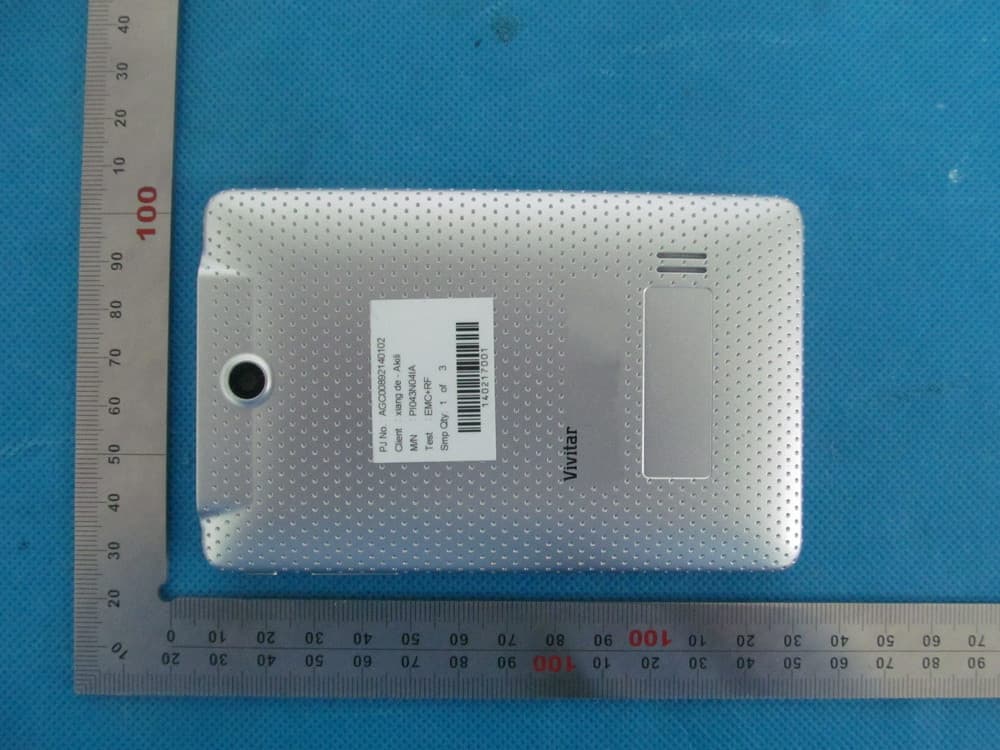
RQ2PI043N04IA
Apr 30, 2014Tablet PC
Equipment Class
DTS - Digital Transmission System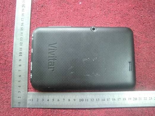
Jun 05, 2013
Equipment Class
DTS - Digital Transmission System