Text extracted from the exhibit documents filed with the FCC. Open a document above to read the original.
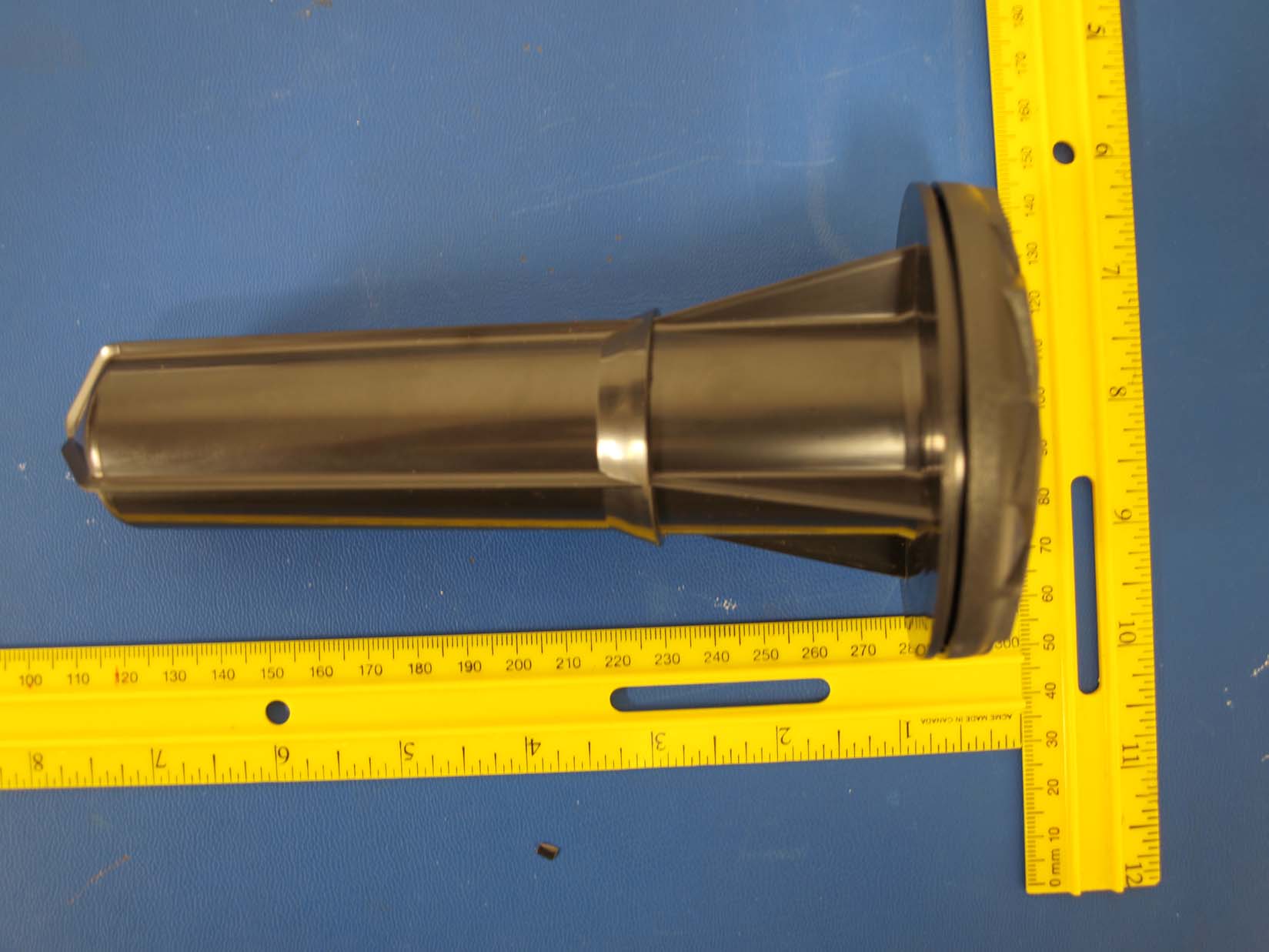
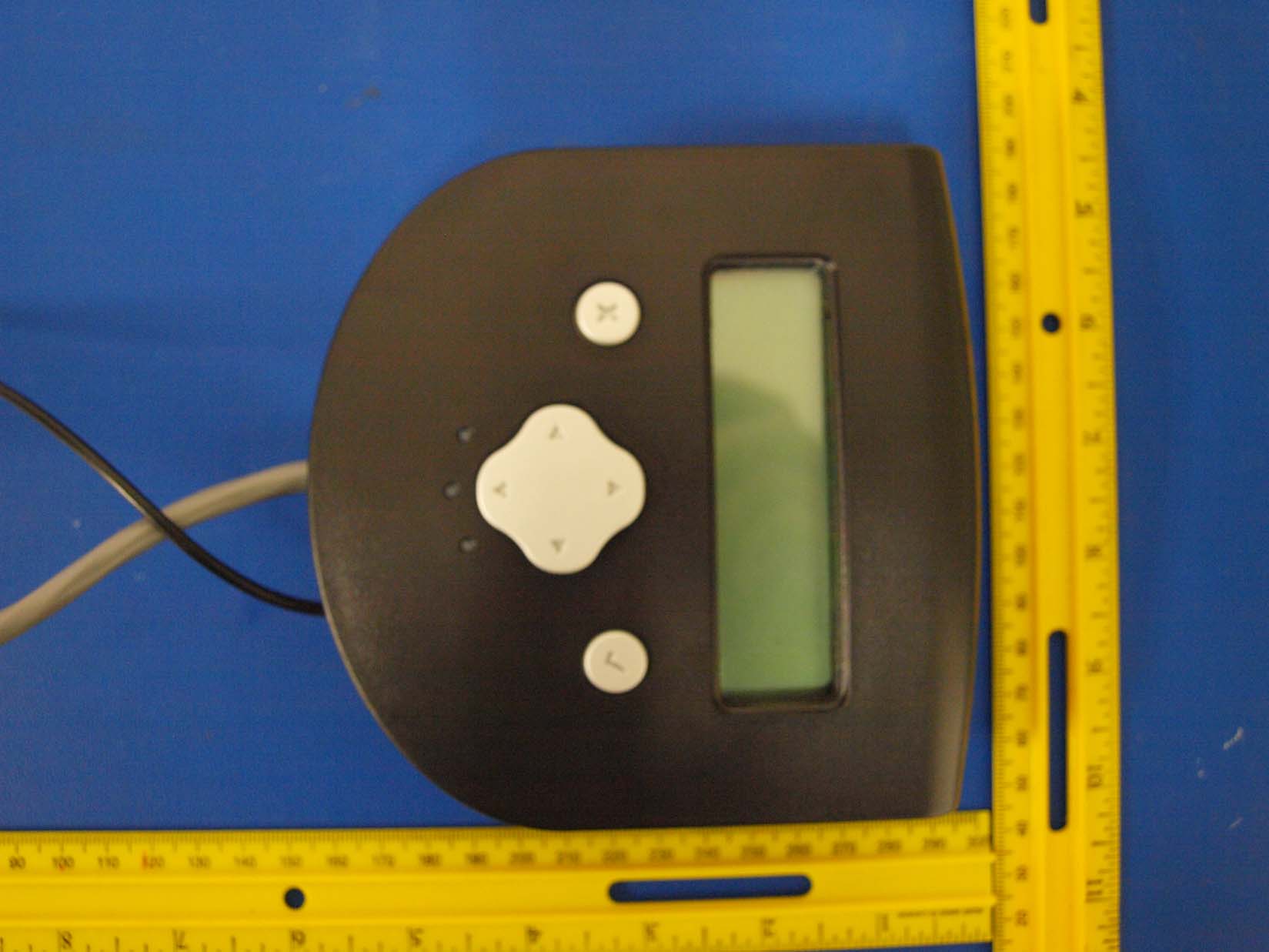
Parts of the S.Sense Network . Your Irrigation Controller The S.Sense System is designed to work with your existing Irrigation Controller. Most controllers, no matter the brand, tend to work in much the same way. In order to get the best results out of the system, your irrigation controller will need to be configured properly for cooperation with the S.Sense Receiver. The good news is, it will be a very simple configuration. Probably the same or close to the default setup of your controller. We will cover this a little later. . Sensors The S.Sense Sensor is a computer that you stick in the ground! It contains a sophisticated micro-controller, a radio transceiver, and sensors that monitor battery charge, soil temperature, and soil moisture levels. The purpose of a Sensor is to tell the Receiver what the conditions are at that location in your lawn and garden. It does this by periodically sending radio messages to the Receiver. Because we are running off a set of batteries for a year, the radio transceiver runs at a very low power level. Which is fine for the short distances involved if you are careful to install the Sensor is a location that “sees” the Receiver. We will cover this is detail in the section on “Planting Your Sensor.” The Receiver The Receiver is the “hub” of the S.Sense Network. It monitors the health and status of Sensors in its network, gathers data reported by its Sensors, monitors the watering cycles of the Controller, and analizes all these factors to decide when, and if, to irrigate. It also has the User Interface on its front that allows you to customize and adjust the settings for your particular garden and its plants. Installation Designing Your Yard Network This is all about placement. Putting the Receiver and Sensors in the right place will determine just how well, or if, your S.Sense System works. The critical items in Receiver placement are: . Controller Wires – Ideally the Receiver will be mounted next to the controller, but sometimes that location will not work. So you many need to extend the wires of the Receiver so they reach the controller from where the Receiver needs to be mounted. 0. Line of sight to the Sensor – This means the from the location you intend to mount the Receiver's Antenna, you should be able to see the area when you plan to put the Sensor. 0. Protection – The Receiver is not water-proof so the mounting location should be protected. Most home irrigation controllers are not waterproof, so it is already in a safe location that you can also use for the Receiver. If you must install the S.Sense Receiver outside, then put it inside a plastic controller box (available at the irrigation section of hardware stores) . . Access – The Front Panel Interface should be in a comfortable location when you use it. If your yard's soil or drainage vary a lot, you might be better served if you add additional sensors, putting one in each distinctive area. S.Sense will use the data from all the Sensors to determine how to water. One other note on your Yard Design – Write it down. After your Sensor has been in the ground for a year, it can be much harder to find that you expect. Your memory will not be enough and in any case grass and shrubs may have grown over the Sensor. Carefully measure the location from stable landmarks, such as a tree or irrigation standpipe, then write it down on the flyleaf of this manual. A year from now, when it's time to replace the Sensor's battery, you will be glad you did. Keep the manual in a safe place you will remember later. . Setting up your Controller Remember, the S.Sense System controls if a watering will occur, but it cannot turn the water on. The times, dates and duration of a watering cycle is still the responsibility of your controller. If your municipality has any watering date restrictions, then be sure to continue setting the Controller to not violate “no water” times. Currently, you probably adjust your controller's settings regularly, compensating for seasonal variations or rainfall. Or if you are like me, you set it up once being generous on the watering so nothing dies in the hottest part of the summer, then just leave it on that setting for all the year. For lazy people like me, there is good news – You are probably already setup perfectly for S.Sense cooperation! We want the Controller to try to water as often and as much as would be needed on the hottest, driest summer day. The Receiver will keep the Controller from over-watering. When the S.Sense data and analysis indicate that the lawn and garden have sufficient moisture to last to at least the next scheduled water cycle, it blocks the current water cycle from starting. So while the Controller will try to irrigate often, the end result is the watering only happens when it is needed. If you have carefully programmed your controller to do just the correct amount of watering, then you need to relax the settings a little. Change the Controller back to its hot summer watering schedule. . Installing the Receiver [ILLISTRATION - Receiver Bottom goes here – arrows point to: Power and Sense wire bundle with 4 wires separated and labeled as . Black - GROUND, . Red - POWER, . Green - COMMON and White - COMMON ] We begin with mounting the Receiver to the location you have selected. Attach the mounting plate to the wall or other surface. The Receiver slips down into the bracket and will lock in place. The Antenna is connected to the Receiver by a six foot long coaxial cable. Mount the Antenna as high as practical to give the best line of sight to the Sensors. Aluminum siding, stucco siding and metal downspouts tend to interfere with the radio transmissions from the antenna, so it is important to keeps metal items out of the path between the Receiver's antenna and the sensors. Next, connect one of the Common Wires to the Common on your Irrigation Controller's wiring strip. [ILLISTRATION – Arrow to Common on Controllers] There should already be a wire attached to the Comm…
Text truncated - open the document above for the full version.
@o,nnat sun, lnc. DATE: October 14,2009 Federal Communications Commission E quipment Authorization branch 7435 Oakland Mills Road Columbia, MD 21046 Re: Request for Confidentiality Gentlemen: In ref'erence to the application under t''CC ID : RQT-SSI0RA, and pursuant to Sections 0.457(dxl)(ii) and 0.459 of the Commission's Rules, the Applicant hereby requests confidential treatment of the accompanying information as outlined below: Schematics Block Diagrams Theory of Operation These documents contain detailed system and equipment description and related information about the product that Digital Sun, Inc. considers to be proprietary, confidential, and a custom design and, otherwise, would not release to the general public. Since this design is a basis from which future technological products will evolve, Digital Sun, Inc. considers that this information would be of benefit to its competitors, and that disclosure of the infbrmation in these documents would give competitors an unfair advantage in the market. Sincerely, - ,'4 'i,',.7 ./ / .2.- , '/ "/1'1 ' Dale Hitt CEO Digital Sun. Inc. Digital Sun, lnc. 5655 Silver Creek Valley Rd. #434, San Jose, CA 95138
MODEL:SS10-S FCC ID:RQT-SS10SA SNUM:50000 MADE IN USA MODEL:SS10-R FCC ID:RQT-SS10RA SNUM:10000 MADE IN USA This device complies with part 15 of the FCC Rules. Operation is subject to the following two conditions: (1) This device may not cause harmful interference, and (2) This device must accept any interference received, including interference that may cause undesired operation. label format for receiver: FCC ID:RQT-SS10RA SNUM:10000 MODEL:SS10-R FCC ID:RQT-SS10RA SNUM:10000 MADE IN USA Label format for the probe FCC ID:RQT-SS10SA SNUM:50000 Label Location for the Probe (Sensor FCC ID: RQT-SS10SA): Label location on Sensor is on the inside sensor assembly...along the side between the battery compartments. Label Location for the Receiver(FCC ID: RQT-SS10RA): Label location on Receiver is on the back, above the mounting bracket..in the middle.
Frequency Range2.4~2.5GHz Impedance50Ω V.S.W.R.≦ 2.0 RadiationOmni-directional Gain2 dBi PolarizationVertical Connector TypeSMA Plug (Reverse Polarity) MaterialPU / - Length88 mm Bushing Type- Water ProofIP65 Mechanical Mechanical WiFi Straight, Replacement Antenna Model No.: WJW-83310-IHX Electrical Water ProofIP65 Weight10 g Operating Temp -20 ~ +65 °C Storage Temp -30 ~ +70°C SubstanceMeets RoHs requirement Pattern Environmental Specification Unit : mm Joycell Enterprise Company Rev. 1.0 Date: May 01.2008 Hong Kong: Rm.No.1001, 10F, No.720-722, Nathen Road, Monkok, Kowloon H.K. Taiwan: 1F, No. 9, Lane 20, Dazhi Street, Taipei 104, Taiwan, R.O.C.
FCC CFR47 PART 15 SUBPART B FCC CFR47 PART 15 SUBPART C CERTIFICATION TEST REPORT FOR BASE STATION RECEIVER MODEL NUMBER: SS10-R FCC ID: RQT-SS10RA REPORT NUMBER: 09U12762-2 ISSUE DATE: AUGUST 21, 2009 Prepared for DIGITAL SUN, INC. 5655 SILVER CREEK VALLEY ROAD, SUIT 434 SAN JOSE, CA 95138, U.S.A. Prepared by COMPLIANCE CERTIFICATION SERVICES 47173 BENICIA STREET FREMONT, CA 94538, U.S.A. TEL: (510) 771-1000 FAX: (510) 661-0888 REPORT NO: 09U12762-2 DATE: AUGUST 21, 2009 FCC ID: RQT-SS10RA MODEL: SS10-R Page 2 of 61 COMPLIANCE CERTIFICATION SERVICES FORM NO: CCSUP4701C 47173 BENICIA STREET, FREMONT, CA 94538, USA TEL: (510) 771-1000 FAX: (510) 661-0888 This report shall not be reproduced except in full, without the written approval of CCS. Revision History Rev. Issue Date Revisions Revised By -- 08/21/09 Initial Issue F. Ibrahim REPORT NO: 09U12762-2 DATE: AUGUST 21, 2009 FCC ID: RQT-SS10RA MODEL: SS10-R Page 3 of 61 COMPLIANCE CERTIFICATION SERVICES FORM NO: CCSUP4701C 47173 BENICIA STREET, FREMONT, CA 94538, USA TEL: (510) 771-1000 FAX: (510) 661-0888 This report shall not be reproduced except in full, without the written approval of CCS. TABLE OF CONTENTS 1. ATTESTATION OF TEST RESULTS.................................................................................... 4 2. TEST METHODOLOGY ........................................................................................................ 5 3. FACILITIES AND ACCREDITATION.................................................................................... 5 4. CALIBRATION AND UNCERTAINTY .................................................................................. 5 4.1. MEASURING INSTRUMENT CALIBRATION ............................................................... 5 4.2. SAMPLE CALCULATION.............................................................................................. 5 4.3. MEASUREMENT UNCERTAINTY................................................................................ 5 5. EQUIPMENT UNDER TEST ................................................................................................. 6 5.1. DESCRIPTION OF EUT................................................................................................ 6 5.2. MAXIMUM OUTPUT POWER....................................................................................... 6 5.3. DESCRIPTION OF AVAILABLE ANTENNAS............................................................... 6 5.4. SOFTWARE AND FIRMWARE..................................................................................... 6 5.5. WORST-CASE CONFIGURATION AND MODE .......................................................... 7 5.6. DESCRIPTION OF TEST SETUP................................................................................. 8 6. TEST AND MEASUREMENT EQUIPMENT ....................................................................... 12 7. ANTENNA PORT TEST RESULTS .................................................................................... 13 7.1. 802.15.4 ZIGBEE MODE IN THE 2.4 GHz BAND ...................................................... 13 7.1.1. 6 dB BANDWIDTH .............................................................................................. 13 7.1.2. OUTPUT POWER ............................................................................................... 17 7.1.3. AVERAGE POWER ............................................................................................ 21 7.1.4. POWER SPECTRAL DENSITY .......................................................................... 22 7.1.5. CONDUCTED SPURIOUS EMISSIONS............................................................. 26 7.2. TRANSMITTER ABOVE 1 GHz .................................................................................. 33 7.3. WORST-CASE BELOW 1 GHz................................................................................... 42 7.4. DIGITAL DEVICE BELOW 1 GHz............................................................................... 45 8. AC POWER LINE CONDUCTED EMISSIONS ................................................................... 48 9. MAXIMUM PERMISSIBLE EXPOSURE ............................................................................. 52 10. SETUP PHOTOS ............................................................................................................ 55 REPORT NO: 09U12762-2 DATE: AUGUST 21, 2009 FCC ID: RQT-SS10RA MODEL: SS10-R Page 4 of 61 COMPLIANCE CERTIFICATION SERVICES FORM NO: CCSUP4701C 47173 BENICIA STREET, FREMONT, CA 94538, USA TEL: (510) 771-1000 FAX: (510) 661-0888 This report shall not be reproduced except in full, without the written approval of CCS. 1. ATTESTATION OF TEST RESULTS COMPANY NAME: DIGITAL SUN, INC. 5655 SILVER CREEK VALLEY ROAD, SUIT 434 SAN JOSE, CA 95138, U.S.A. EUT DESCRIPTION: BASE STATION RECEIVER MODEL: SS10-R SERIAL NUMBER: 60128 DATE TESTED: AUGUST 11 TO 13, 2009 APPLICABLE STANDARDS STANDARD TEST RESULTS CFR 47 Part 15 Subpart C Pass Compliance Certification Services, Inc. (CCS) tested the above equipment in accordance with the requirements set forth in the above standards. All indications of Pass/Fail in this report are opinions expressed by CCS based on interpretations and/or observations of test results. Measurement Uncertainties were not taken into account and are published for informational purposes only. The test results show that the equipment tested is capable of demonstrating compliance with the requirements as documented in this report. Note: The results documented in this report apply only to the tested sample, under the conditions and modes of operation as described herein. This document may not be altered or revised in any way unless done so by CCS and all revisions are duly noted in the revisions section. Any alteration of this document not carried out by CCS will constitute fraud and shall nullify the document. This report must not be used by the client to claim product certification, approval, or e…
Text truncated - open the document above for the full version.
REPORT NO: 09U12762-2 DATE: AUGUST 21, 2009 FCC ID: RQT-SS10RA MODEL: SS10-R Page 55 of 61 COMPLIANCE CERTIFICATION SERVICES FORM NO: CCSUP4701C 47173 BENICIA STREET, FREMONT, CA 94538, USA TEL: (510) 771-1000 FAX: (510) 661-0888 This report shall not be reproduced except in full, without the written approval of CCS. 10. SETUP PHOTOS ANTENNA PORT CONDUCTED RF MEASUREMENT SETUP ANTENNA PORT CONDUCTED PHOTO REPORT NO: 09U12762-2 DATE: AUGUST 21, 2009 FCC ID: RQT-SS10RA MODEL: SS10-R Page 56 of 61 COMPLIANCE CERTIFICATION SERVICES FORM NO: CCSUP4701C 47173 BENICIA STREET, FREMONT, CA 94538, USA TEL: (510) 771-1000 FAX: (510) 661-0888 This report shall not be reproduced except in full, without the written approval of CCS. RADIATED RF MEASUREMENT SETUP RADIATED FRONT PHOTO REPORT NO: 09U12762-2 DATE: AUGUST 21, 2009 FCC ID: RQT-SS10RA MODEL: SS10-R Page 57 of 61 COMPLIANCE CERTIFICATION SERVICES FORM NO: CCSUP4701C 47173 BENICIA STREET, FREMONT, CA 94538, USA TEL: (510) 771-1000 FAX: (510) 661-0888 This report shall not be reproduced except in full, without the written approval of CCS. RADIATED BACK PHOTO REPORT NO: 09U12762-2 DATE: AUGUST 21, 2009 FCC ID: RQT-SS10RA MODEL: SS10-R Page 58 of 61 COMPLIANCE CERTIFICATION SERVICES FORM NO: CCSUP4701C 47173 BENICIA STREET, FREMONT, CA 94538, USA TEL: (510) 771-1000 FAX: (510) 661-0888 This report shall not be reproduced except in full, without the written approval of CCS. DIGITAL DEVICE RADIATED EMISSIONS SETUP DIGITAL DEVICE FRONT PHOTO REPORT NO: 09U12762-2 DATE: AUGUST 21, 2009 FCC ID: RQT-SS10RA MODEL: SS10-R Page 59 of 61 COMPLIANCE CERTIFICATION SERVICES FORM NO: CCSUP4701C 47173 BENICIA STREET, FREMONT, CA 94538, USA TEL: (510) 771-1000 FAX: (510) 661-0888 This report shall not be reproduced except in full, without the written approval of CCS. DIGITAL DEVICE BACK PHOTO REPORT NO: 09U12762-2 DATE: AUGUST 21, 2009 FCC ID: RQT-SS10RA MODEL: SS10-R Page 60 of 61 COMPLIANCE CERTIFICATION SERVICES FORM NO: CCSUP4701C 47173 BENICIA STREET, FREMONT, CA 94538, USA TEL: (510) 771-1000 FAX: (510) 661-0888 This report shall not be reproduced except in full, without the written approval of CCS. POWERLINE CONDUCTED EMISSIONS MEASUREMENT SETUP LINE CONDUCTED FRONT PHOTO REPORT NO: 09U12762-2 DATE: AUGUST 21, 2009 FCC ID: RQT-SS10RA MODEL: SS10-R Page 61 of 61 COMPLIANCE CERTIFICATION SERVICES FORM NO: CCSUP4701C 47173 BENICIA STREET, FREMONT, CA 94538, USA TEL: (510) 771-1000 FAX: (510) 661-0888 This report shall not be reproduced except in full, without the written approval of CCS. END OF REPORT LINE CONDUCTED BACK PHOTO
| # | Rule Parts | Frequency Range | Power Output |
|---|---|---|---|
| 1 | 15C | 2.40 GHz - 2.48 GHz | 107.40 mW |

Sensor Probe
Equipment Class
DTS - Digital Transmission System