RRK20031200281High Speed 2.4GHz WLAN Mini PCI Card
Alpha Networks Inc.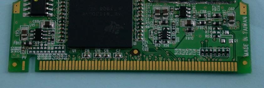
Click to zoom
Application Details
- Equipment Class
- DTS - Digital Transmission System
- Date of Grant
- Mar 18, 2004
- Application Purpose
- Original Equipment
- Date of Application
- Mar 18, 2004
- Equipment Note
- High Speed 2.4GHz WLAN Mini PCI Card
- Frequency Range
- 2412.00000000 - 2462.00000000
- Company
- Alpha Networks Inc.
- Country
- Taiwan
Documents & Files
Document Text
Text extracted from the exhibit documents filed with the FCC. Open a document above to read the original.
Users Manual
Manual 2.4GHz up to 54Mbps D-Link WMP-G04 Wireless Mini PCI Card 2 Contents Introduction ......................................................................................................3 Wireless Basics ...............................................................................................56 Getting Started ................................................................................................. 9 Using the Configuration Utility .................................................................... 12 Networking Basics ....................................................................................... 18 Warranty and Registration............................................................................. 31 3 Introduction The Alpha Networks WMP-G04 Wireless Mini PCI Card is an enhanced 802.11g high-performance, wireless adapter that supports high-speed wireless networking at home, at work or in public places. Unlike most network cards, the WMP-G04 provides speeds of up to 54 Mbps (compared to the standard 11 Mbps) This means that you do not need to change your entire network to maintain connectivity. You may sacrifice some of 802.11g’s speed when you mix 802.11b and 802.11g devices, but you will not lose the ability to communicate when you incorporate the 802.11g standard into your 802.11b network. You may choose to slowly change your network by replacing the 802.11b devices with 802.11g devices gradually. In addition to offering faster data transfer speeds when used with other 802.11g products, the WMP-G04 has the newest, strongest, most advanced security features available today. For home users that will not incorporate a radius server in their network, the security for the WMP-G04, used in conjunction with other 802.11g products, will be much stronger than ever before. No longer will you have to manually input a new WEP key frequently to ensure security, with the WMP-G04, you will automatically receive a new key every time you connect, vastly increasing the safety of your communications. 4 The WMP-G04 is compatible with existing 802.11b devices such as the AirPlus, AirPlusXtremeG and AirPremier family of products including the DWL-520, DWL-520+ and the DWL-AG530 Wireless PCI Adapter, the DI-624 Wireless Router/Access Point and the DWL-120 Wireless USB Adapter. (When used with 802.11b devices, the WMP-G04 will reach speeds at up to 11Mbps.) It is an ideal way to connect one laptop computer to a Wireless Local Area Network (WLAN.) After completing the steps outlined in the Quick Installation Guide (included in the package) you will have the ability to share information and resources, such as files and printers, and take full advantage of a “connected” environment for work or play! The WMP-G04 includes software drivers for the most popular Microsoft Windows operating systems (Windows XP, Windows 2000, Windows Me, Windows 98(SE)) and can be integrated into a larger network, running, in either Peer-to-Peer mode (without an Access Point) or mode (with an Access Point.) Please take a look at our Getting Started section in this manual to see examples of typical network setups using the WMP-G04 in both Access Point and Peer-to-Peer modes. This manual provides a quick introduction to wireless technology and its application as it relates to networking. Take a moment to read through this manual and get acquainted with wireless technology. Access Point 5 Alpha wireless products are based on industry standards to provide easy-to- use and compatible high-speed wireless connectivity within your home, business or public access wireless networks. Strictly adhering to the IEEE standard, the Alpha wireless family of products will allow you to securely access the data you want, when and where you want it. You will be able to enjoy the freedom that wireless networking delivers. A wireless local area network (WLAN) is a cellular computer network that transmits and receives data with radio signals instead of wires. Wireless LANs are used increasingly in both home and office environments, and public areas such as airports, coffee shops and universities. Innovative ways to utilize WLAN technology are helping people to work and communicate more efficiently. Increased mobility and the absence of cabling and other fixed infrastructure have proven to be beneficial for many users. Wireless Basics Wireless users can use the same applications they use on a wired network. Wireless adapter cards used on laptop and desktop systems support the same protocols as Ethernet adapter cards. Under many circumstances, it may be desirable for mobile network devices to link to a conventional Ethernet LAN in order to use servers, printers or an Internet connection supplied through the wired LAN. A Wireless Router is a device used to provide this link. 6 Wireless Basics (continued) People use wireless LAN technology for many different purposes: Mobility - Productivity increases when people have access to data in any location within the operating range of the WLAN. Management decisions based on real-time information can significantly improve worker efficiency. Low Implementation Costs – WLANs (Wireless Local Area Networks) are easy to set up, manage, change and relocate. Networks that frequently change, both physically and logically, can benefit from WLANs ease of implementation. WLANs can operate in locations where installation of wiring may be impractical. Installation Speed and Simplicity - Installing a wireless LAN system can be fast and easy and can eliminate the need to pull cable through walls and ceilings. Network Expansion - Wireless technology allows the network to go where wires cannot. Scalability – Wireless Local Area Networks (WLANs) can be configured in a variety of topologies to meet the needs of specific applications or existing infrastructures. Configurations are easily changed and range from peer-to- peer networks suitable for a small number of users to larger infrastructure networks to acc…
Text truncated - open the document above for the full version.
Cover Letter(s)
FCC ID: RRK20031200281 Report No.: RF930305R01 Modular Approval Request Letter Advance Data Technology Mar. 12, 2004 Dear Application Examiner, Alpha Networks Inc., It’s High-Speed 2.4GHz WLAN Mini PCI Card, FCC ID: RRK20031200281, would like to have your authorization as a limited modular approval specific to the mobile device such as Access Point. The requirements of Public Notice DA00-1407 have been met and shown on the following statements. 1. “The modular transmitter must have its own RF shielding.”: The radio portion of this module has been shielded, please see exhibition External Photo. 2. “The modular transmitter must have buffered modulation/data inputs.” The EUT has buffered data inputs, it is integrated in chip TNET1130GHV BGA288. 3. “The modular transmitter must have its own power supply regulation.” The chips IF converter and RF/IF converter which will influence the frequency radiation, have to be 2.25V DC powered. The mini-pci interface provides 3.3VDC, so there are regulators in front of these chips, the part number of this regulator is TPS793285. 4. “The modular transmitter must comply with the antenna requirements of section 15.203 and 15.204(C).” The EUT meets the FCC antenna requirements. The spurious emission, unique antenna connector and photo of antennas are shown in the test report. 5. “The modular transmitter must be tested in a stand-alone configuration” The EUT was tested in a stand-alone configuration via a PCMCIA to mini-PCI extender. Please see section Photographs of Test Configuration in the test report, the EUT was plugged in this extender. 6. “The modular transmitter must be labeled with its own FCC ID number.” Please see exhibition Label Sample for the FCC ID of this module. And also in the exhibition Users Manual, there are instructions give to the OEM on how to label the end product. FCC ID: RRK20031200281 Report No.: RF930305R01 7. “The modular transmitter must comply with any specific rule or operating requirements applicable to the transmitter and the manufacturer must provide adequate instructions along with the module to explain any such requirements.” The EUT is compliant with all applicable FCC rules. Detail instructions for maintaining compliance are given in the Users Manual. 8. “The modular transmitter must comply with any applicable RF exposure requirements.” The EUT is compliant with all applicable RF exposure requirements. RF Exposure is addressed in the RF exposure exhibition. Please contact me if you have any further questions. Thanks for your attention. Best Regards, Ellis Wu Manager Advance Data Technology
External Photos
Page 1 CONSTRUCTION PHOTOS OF EUT Alpha Networks Inc. WMP-G04 Alpha Networks Inc. WMP-G04 Page 2 Alpha Networks Inc. WMP-G04 Alpha Networks Inc. WMP-G04 Page 3 Alpha Networks Inc. WMP-G04 Alpha Networks Inc. WMP-G04 Page 4
ID Label/Location Info
Label Location
Internal Photos
Page 5 Alpha Networks Inc. WMP-G04 Alpha Networks Inc. WMP-G04 Page 6 Page 7
Operational Description
FCC ID: RRK20031200281 Report No. 930305R01 Operational Description This device is a High-Speed 2.4GHz WLAN Mini PCI Card which operates in the 2.4GHz frequency spectrum with throughput of up to 54Mbps which OFDM technique will be applied. If the signal to noise radio is too poor which could not support 54Mbps, the 11Mbps data rate with CCK technique will be applied. The transmitter of the EUT is powered by host equipment via mini-PCI interface. The antennas are PIFA antenna (Internal) and Swivel Dipole antenna (External) with UFL connector. Under normal use condition, the user has to keep at least 20cm separation distance between radiator and the body of the user. The other instruction, please have a look at the users manual.
RF Exposure Info
FCC ID: RRK20031200281 Report No: SA930305R01 1 RF EXPOSURE REPORT REPORT NO.: SA930305R01 MODEL NO.: WMP-G04 ACCORDING: FCC Guidelines for Human Exposure IEEE C95.1 APPLICANT: Alpha Networks Inc. ADDRESS: No.8, Li-shing 7th Rd., Science-based Industrial Park, Hsinchu, Taiwan ISSUED BY: Advance Data Technology Corporation LAB LOCATION: 47 14th Lin, Chiapau Tsun, Linko, Taipei, Taiwan, R.O.C. FCC ID: RRK20031200281 Report No: SA930305R01 2 RF Exposure Measurement (Mobile Device) 1. Introduction In this document, we try to prove the safety of radiation harmfulness to the human body for our product. The limit for Maximum Permissible Exposure (MPE) specified in FCC 1.1310 is followed. The Gain of the antenna used in this product is measured in a Fully Anechoic Chamber (FAC) calibrated for antenna measurement in ADT, and also the maximum total power input to the antenna is measured. Through the Friis transmission formula and the maximum gain of the antenna, we can calculate the distance, away from the product, where the limit of MPE is reached. Although the Friis transmission formula is a far field assumption, the calculated result of that is an over-prediction for near field power density. We will take that as the worst case to specify the safety range. 2. RF Exposure Limit According to FCC 1.1310: The criteria listed in the following table shall be used to evaluate the environmental impact of human exposure to radio-frequency (RF) radiation as specified in 1.1307(b) LIMITS FOR MAXIMUM PERMISSIBLE EXPOSURE (MPE) Frequency Range (MHz) Electric Field Strength (V/m) Magnetic Field Strength (A/m) Power Density (mW/cm 2 ) Average Time (minutes) (A)Limits For Occupational / Control Exposures 300-1500......F/3006 1500-100,000......56 (B)Limits For General Population / Uncontrolled Exposure 300-1500......F/15006 1500-100,000......1.030 F = Frequency in MHz FCC ID: RRK20031200281 Report No: SA930305R01 3 3. Friis Formula Friis transmission formula : Pd = (Pout*G) / (4*pi*r 2 ) where Pd = power density in mW/cm 2 Pout = output power to antenna in mW G = gain of antenna in linear scale Pi = 3.1416 R = distance between observation point and center of the radiator in cm If we know the maximum Gain of the antenna and the total power input to the antenna, through the calculation, we will know the MPE value at distance r. Ref. : David K. Cheng, Field and Wave Electromagnetics, Second Edition, Page 640, Eq. (11-133). 4. EUT Operating condition The software provided by Manufacturer enabled the EUT to transmit and receive data at lowest, middle and highest channel individually. 5. Classification This modular is specified to be installed in access point which is connected with host through wire. So it is easy to be re-located in the place where at least 20cm far away from the body of the user. Warning statement to the user for keeping at least 20cm or more separation distance with the antenna should be included in users manual. So, this device is classified as Mobile Device. FCC ID: RRK20031200281 Report No: SA930305R01 4 6. Test Results 6.1 Antenna Gain The maximum Gain measured in Fully Anechoic Chamber is 2dBi or 1.585 (numeric) 6.2 Output Power Into Antenna & RF Exposure value at distance 20cm: For CCK technique: Channel Channel Frequency (MHz) Output Power to Antenna (mW) Power Density (mW/cm 2 ) Limit of Power Density (mW/cm 2 ) 1241256.2340.0181.0 6243756.2340.0181.0 11246254.9540.0181.0 For OFDM technique: Channel Channel Frequency (MHz) Output Power to Antenna (mW) Power Density (mW/cm 2 ) Limit of Power Density (mW/cm 2 ) 1241222.3870.0071.0 6243721.8780.0071.0 11246222.3870.0071.0
Test Report
FCC ID: RRK20031200281 Report No.: RF930305R011Issued: Mar. 12, 2004 FCC TEST REPORT REPORT NO.: RF930305R01 MODEL NO.: WMP-G04 RECEIVED: Mar. 5, 2004 TESTED: Mar. 8 ~ Mar. 10, 2004 APPLICANT: Alpha Networks Inc. ADDRESS: No. 8, Li-shing 7th Rd, Science-based Industrial Park, Hsinchu, Taiwan, R.O.C. ISSUED BY: Advance Data Technology Corporation LAB LOCATION: 47 14th Lin, Chiapau Tsun, Linko, Taipei, Taiwan, R.O.C. This test report consists of 67 pages in total. It may be duplicated completely for legal use with the approval of the applicant. It should not be reproduced except in full, without the written approval of our laboratory. The client should not use it to claim product endorsement by CNLA or any government agencies. The test results in the report only apply to the tested sample. 0528 ILAC MRA FCC ID: RRK20031200281 Report No.: RF930305R012Issued: Mar. 12, 2004 Table of Contents 1CERTIFICATION ........................................................................................... 4 2SUMMARY OF TEST RESULTS................................................................... 5 3GENERAL INFORMATION ........................................................................... 6 3.1GENERAL DESCRIPTION OF EUT.............................................................. 6 3.2DESCRIPTION OF TEST MODES................................................................ 7 3.3GENERAL DESCRIPTION OF APPLIED STANDARDS ............................... 7 3.4DESCRIPTION OF SUPPORT UNITS .......................................................... 8 3.5CONFIGURATION OF SYSTEM UNDER TEST........................................... 8 4TEST TYPES AND RESULTS....................................................................... 9 4.1CONDUCTED EMISSION MEASUREMENT ................................................ 9 4.1.1LIMITS OF CONDUCTED EMISSION MEASUREMENT.............................. 9 4.1.2TEST INSTRUMENTS .................................................................................. 9 4.1.3TEST PROCEDURES................................................................................. 10 4.1.4DEVIATION FROM TEST STANDARD ....................................................... 10 4.1.5TEST SETUP ...............................................................................................11 4.1.6EUT OPERATING CONDITIONS.................................................................11 4.1.7TEST RESULTS.......................................................................................... 12 4.2RADIATED EMISSION MEASUREMENT ................................................... 18 4.2.1LIMITS OF RADIATED EMISSION MEASUREMENT................................. 18 4.2.2TEST INSTRUMENTS ................................................................................ 19 4.2.3TEST PROCEDURES................................................................................. 20 4.2.4DEVIATION FROM TEST STANDARD ....................................................... 20 4.2.5TEST SETUP .............................................................................................. 21 4.2.6EUT OPERATING CONDITIONS................................................................ 21 4.2.7.TEST RESULTS.......................................................................................... 22 4.36dB BANDWIDTH MEASUREMENT .......................................................... 30 4.3.1LIMITS OF 6dB BANDWIDTH MEASUREMENT ........................................ 30 4.3.2TEST INSTRUMENTS ................................................................................ 30 4.3.3TEST PROCEDURE ................................................................................... 30 4.3.4DEVIATION FROM TEST STANDARD ....................................................... 30 4.3.5TEST SETUP .............................................................................................. 30 4.3.6EUT OPERATING CONDITIONS................................................................ 30 4.3.7TEST RESULTS.......................................................................................... 31 4.4MAXIMUM PEAK OUTPUT POWER .......................................................... 39 FCC ID: RRK20031200281 Report No.: RF930305R013Issued: Mar. 12, 2004 4.4.1LIMITS OF MAXIMUM PEAK OUTPUT POWER MEASUREMENT ........... 39 4.4.2TEST INSTRUMENTS ................................................................................ 39 4.4.3TEST PROCEDURES................................................................................. 40 4.4.4DEVIATION FROM TEST STANDARD ....................................................... 40 4.4.5TEST SETUP .............................................................................................. 40 4.4.6EUT OPERATING CONDITIONS................................................................ 40 4.4.7TEST RESULTS.......................................................................................... 41 4.5POWER SPECTRAL DENSITY MEASUREMENT...................................... 42 4.5.1LIMITS OF POWER SPECTRAL DENSITY MEASUREMENT ................... 42 4.5.2TEST INSTRUMENTS ................................................................................ 42 4.5.3TEST PROCEDURE ................................................................................... 42 4.5.4DEVIATION FROM TEST STANDARD ....................................................... 42 4.5.5TEST SETUP .............................................................................................. 42 4.5.6EUT OPERATING CONDITIONS................................................................ 42 4.5.7TEST RESULTS.......................................................................................... 43 4.6BAND EDGES MEASUREMENT ................................................................ 51 4.6.1LIMITS OF BAND EDGES MEASUREMENT ............................................. 51 4.6.2TEST INSTRUMENTS ...............................…
Text truncated - open the document above for the full version.
Test Report
FCC ID: RRK20031200281 Report No.: RF930305R0141Issued: Mar. 12, 2004 4.4.7 TEST RESULTS EUT High-Speed 2.4GHz WLAN Mini PCI Card MODEL WMP-G04 ENVIRONMENTAL CONDITIONS 22deg. C, 68%RH, 991 hPa INPUT POWER (SYSTEM) 120Vac, 60 Hz TEST MODEA TESTED BY Steven Lu CHANNEL CHANNEL FREQUENCY (MHz) PEAK POWER OUTPUT (dBm) PEAK POWER LIMIT (dBm) PASS/FAIL 1241217.5030PASS 6243717.5030PASS 11246217.4030PASS EUT High-Speed 2.4GHz WLAN Mini PCI Card MODEL WMP-G04 ENVIRONMENTAL CONDITIONS 22deg. C, 68%RH, 991 hPa INPUT POWER (SYSTEM) 120Vac, 60 Hz TEST MODEB TESTED BY Steven Lu CHANNEL CHANNEL FREQUENCY (MHz) PEAK POWER OUTPUT (dBm) PEAK POWER LIMIT (dBm) PASS/FAIL 1241213.5030PASS 6243713.4030PASS 11246213.5030PASS FCC ID: RRK20031200281 Report No.: RF930305R0142Issued: Mar. 12, 2004 4.5 POWER SPECTRAL DENSITY MEASUREMENT 4.5.1 LIMITS OF POWER SPECTRAL DENSITY MEASUREMENT The Maximum of Power Spectral Density Measurement is 8dBm. 4.5.2 TEST INSTRUMENTS Description & ManufacturerModel No.Serial No.Calibrated Until SPECTRUM ANALYZERFSEK30100049Aug. 12, 2004 NOTE: The calibration interval of the above test instruments is 12 months and the calibrations are traceable to NML/ROC and NIST/USA. 4.5.3 TEST PROCEDURE The transmitter output was connected to the spectrum analyzer through an attenuator, the bandwidth of the fundamental frequency was measured with the spectrum analyzer using 3kHz RBW and 30kHz VBW, set sweep time=span/3kHz. The power spectral density was measured and recorded. The sweep time is allowed to be longer than span/3KHz for a full response of the mixer in the spectrum analyzer. 4.5.4 DEVIATION FROM TEST STANDARD No deviation 4.5.5 TEST SETUP 4.5.6 EUT OPERATING CONDITIONS Same as 4.3.6 EUT SPECTRUM ANALYZER FCC ID: RRK20031200281 Report No.: RF930305R0143Issued: Mar. 12, 2004 4.5.7 TEST RESULTS EUT High-Speed 2.4GHz WLAN Mini PCI Card MODEL WMP-G04 INPUT POWER (SYSTEM) 120Vac, 60 Hz ENVIRONMENTAL CONDITIONS 22deg. C, 68%RH, 991 hPa TEST MODE A TESTED BYSteven Lu CHANNEL NUMBER CHANNEL FREQUENCY (MHz ) RF POWER LEVEL IN 3 KHz BW (dBm) MAXIMUM LIMIT (dBm) PASS/FAIL 12412-9.048PASS 62437-9.778PASS 112462-8.208PASS FCC ID: RRK20031200281 Report No.: RF930305R0144Issued: Mar. 12, 2004 CH1 FCC ID: RRK20031200281 Report No.: RF930305R0145Issued: Mar. 12, 2004 CH6 FCC ID: RRK20031200281 Report No.: RF930305R0146Issued: Mar. 12, 2004 CH11 FCC ID: RRK20031200281 Report No.: RF930305R0147Issued: Mar. 12, 2004 EUT High-Speed 2.4GHz WLAN Mini PCI Card MODEL WMP-G04 INPUT POWER (SYSTEM) 120Vac, 60 Hz ENVIRONMENTAL CONDITIONS 22deg. C, 68%RH, 991 hPa TEST MODE B TESTED BYJamison Chan CHANNEL NUMBER CHANNEL FREQUENCY (MHz ) RF POWER LEVEL IN 3 KHz BW (dBm) MAXIMUM LIMIT (dBm) PASS/FAIL 12412-15.888PASS 62437-16.368PASS 112462-17.908PASS FCC ID: RRK20031200281 Report No.: RF930305R0148Issued: Mar. 12, 2004 CH1 FCC ID: RRK20031200281 Report No.: RF930305R0149Issued: Mar. 12, 2004 CH6 FCC ID: RRK20031200281 Report No.: RF930305R0150Issued: Mar. 12, 2004 CH11 FCC ID: RRK20031200281 Report No.: RF930305R0151Issued: Mar. 12, 2004 4.6 BAND EDGES MEASUREMENT 4.6.1 LIMITS OF BAND EDGES MEASUREMENT Below –20dB of the highest emission level of operating band (in 100KHz Resolution Bandwidth). 4.6.2 TEST INSTRUMENTS Description & ManufacturerModel No.Serial No.Calibrated Until SPECTRUM ANALYZERFSEK30100049Aug. 12, 2004 NOTE: The calibration interval of the above test instruments is 12 months and the calibrations are traceable to NML/ROC and NIST/USA. 4.6.3 TEST PROCEDURE The transmitter output was connected to the spectrum analyzer via a low lose cable. Set both RBW and VBW of spectrum analyzer to 100kHz and 100kHz with suitable frequency span including 100MHz bandwidth from band edge. The band edges was measured and recorded. 4.6.4 DEVIATION FROM TEST STANDARD No deviation 4.6.5 EUT OPERATING CONDITION Same as Item 4.3.6 FCC ID: RRK20031200281 Report No.: RF930305R0152Issued: Mar. 12, 2004 4.6.6 TEST RESULTS TEST MODE A The spectrum plots are attached on the following 4 pages. D2 line indicates the highest level, D1 line indicates the 20dB offset below D2. It shows compliance with the requirement in part 15.247(C). NOTE: The band edge emission plot on the following 1 ~ 2 pages shows 60.1dB delta between carrier maximum power and local maximum emission in restrict band (2.3868GHz). The emission of carrier strength list in the test mode A of channel 1 at the item 4.2.7 is 101.92dBuV/m, so the maximum field strength in restrict band is 101.92 – 60.1 = 41.82dBuV/m which is under 54 dBuV/m limit. NOTE: The band edge emission plot on the following 3 ~ 4 pages shows 56.85dB delta between carrier maximum power and local maximum emission in restrict band (2.4835GHz). The emission of carrier strength list in the test mode A of channel 11 at the item 4.2.7 is 99.45dBuV/m, so the maximum field strength in restrict band is 99.45 –56.85 = 42.6dBuV/m which is under 54 dBuV/m limit. FCC ID: RRK20031200281 Report No.: RF930305R0153Issued: Mar. 12, 2004 FCC ID: RRK20031200281 Report No.: RF930305R0154Issued: Mar. 12, 2004 FCC ID: RRK20031200281 Report No.: RF930305R0155Issued: Mar. 12, 2004 FCC ID: RRK20031200281 Report No.: RF930305R0156Issued: Mar. 12, 2004 FCC ID: RRK20031200281 Report No.: RF930305R0157Issued: Mar. 12, 2004 TEST MODE B The spectrum plots are attached on the following 4 pages. D2 line indicates the highest level, D1 line indicates the 20dB offset below D2. It shows compliance with the requirement in part 15.247(C). NOTE: The band edge emission plot on the following 1 ~ 2 pages shows 52.44dB delta between carrier maximum power and local maximum emission in restrict band (2.3900GHz). The emission of carrier strength list in the test mode B of channel 1 at the item 4.2.7 is 94.25dBuV/m, so the maximum field strength in restrict band is 94.25 – 52.44 = 41.81dBuV/m which is under 54 dBuV/m limit. NOTE: The band edge emission plot on the following 3 ~ 4 pages shows 53.41dB delta between carrier maximum power and local…
Text truncated - open the document above for the full version.
Test Setup Photos
FCC ID: RRK20031200281 Report No.: RF930305R0163Issued: Mar. 12, 2004 5 PHOTOGRAPHS OF THE TEST CONFIGURATION CONDUCTED EMISSION TEST FCC ID: RRK20031200281 Report No.: RF930305R0164Issued: Mar. 12, 2004 RADIATED EMISSION TEST FCC ID: RRK20031200281 Report No.: RF930305R0165Issued: Mar. 12, 2004
Contact Information
Applicant
Kelly Tsai(Director)
Technical Contact
Advance Data Technology CorporationEllis Wu
[email protected]+886 3318 3232
No. 19 Hwa Ya 2nd rd. Kueishan · Taoyuan · Taiwan
Test Firm
Bureau Veritas CPS (H.K.) Ltd. Taoyuan BranchRichard Chen
Technical Specifications
| # | Rule Parts | Frequency Range | Power Output |
|---|---|---|---|
| 1 | 15C | 2.41 GHz - 2.46 GHz | 56.00 mW |
Other Applications from Alpha Networks Inc.
RRK-MSSS2571
Jul 22, 2026Z-Wave 800 module
Equipment Class
DTS - Digital Transmission SystemRRK-W1700A3
Jul 22, 2026Wi-Fi 7 Router
Equipment Class
6ID - 15E 6 GHz Low Power Indoor Access Point
RRK-BW1600A
Oct 10, 2023LTE Data and Voice (ATA) In-Home Gateway
Equipment Class
NII - Unlicensed National Information Infrastructure TX
RRK-ARSSM01
Feb 08, 202179G Radar
Equipment Class
VRD - Part 95 Vehicular Radar Systems
RRK-ARSSA07
Feb 08, 2021Radar (UART), Radar (CAN)
Equipment Class
VRD - Part 95 Vehicular Radar Systems