RRKWMPD18IEEE 802.11a MiniPCI Card
Alpha Networks Inc.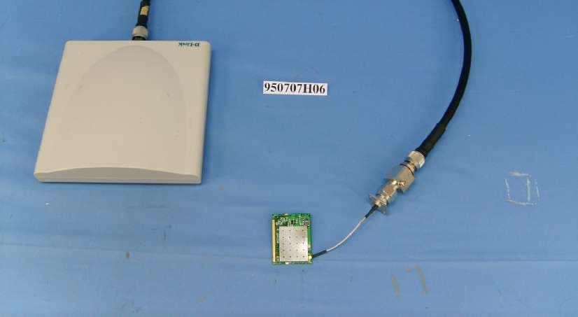
Click to zoom
Application Details
- Equipment Class
- NII - Unlicensed National Information Infrastructure TX
- Date of Grant
- Jul 18, 2006
- Application Purpose
- Original Equipment
- Date of Application
- Jul 18, 2006
- Equipment Note
- IEEE 802.11a MiniPCI Card
- Frequency Range
- 5180.00000000 - 5320.00000000
- Company
- Alpha Networks Inc.
- Country
- Taiwan
Documents & Files
Document Text
Text extracted from the exhibit documents filed with the FCC. Open a document above to read the original.
Users Manual
Installation Guide For WMP-D18 IEEE 802.11a MiniPCI Card 申請DGT使用手冊必須包含之資訊: 經型式認證合格之低功率射頻電機,非經許可,公司、商號或使用者均不得擅自 變更頻率、加大功率或變更原設計之特性及功能。 低功率射頻電機之使用不得影響飛航安全及干擾合法通信;經發現有干擾現象 時,應立即停用,並改善至無干擾時方得繼續使用。 前項合法通信,指依電信法規定作業之無線電通信。 低功率射頻電機須忍受合法通信或工業、科學及醫療用電波輻射性電機設備之干 擾。 在5.25~5.35秭赫(GHz)頻帶內操作之無線資訊傳輸設備,限於室內使用。 Federal Communication Commission Interference Statement This equipment has been tested and found to comply with the limits for a Class B digital device, pursuant to Part 15 of the FCC Rules. These limits are designed to provide reasonable protection against harmful interference in a residential installation. This equipment generates, uses and can radiate radio frequency energy and, if not installed and used in accordance with the instructions, may cause harmful interference to radio communications. However, there is no guarantee that interference will not occur in a particular installation. If this equipment does cause harmful interference to radio or television reception, which can be determined by turning the equipment off and on, the user is encouraged to try to correct the interference by one of the following measures: - Reorient or relocate the receiving antenna. - Increase the separation between the equipment and receiver. - Connect the equipment into an outlet on a circuit different from that to which the receiver is connected. - Consult the dealer or an experienced radio/TV technician for help. This device complies with Part 15 of the FCC Rules. Operation is subject to the following two conditions: (1) This device may not cause harmful interference, and (2) this device must accept any interference received, including interference that may cause undesired operation. FCC Caution: Any changes or modifications not expressly approved by the party responsible for compliance could void the user's authority to operate this equipment. IMPORTANT NOTE: FCC Radiation Exposure Statement: This equipment complies with FCC radiation exposure limits set forth for an uncontrolled environment. This transmitter module is authorized only for use in device where the antenna may be installed so that 20 cm may be maintained between the antenna and users and must not be co-located or operating in conjunction with any other antenna or transmitter. For operation within 5.15 ~ 5.25GHz frequency range, it is restricted to indoor environment. This device is intended only for OEM integrators under the following conditions: 1) This product features the selection of different antennas and adjustments of output power according to the final application and the final product which incorporates this product must be installed by a professional installer who has been properly trained by the supplier. Selling of this product in public retail store is prohibited. 2) Professional installer must carefully consult the professional installation manual and program the conducted output power no more than tested maximum conducted power for each antenna as documented in the manual 3) The antenna of end product must be installed so that at least 20 cm is maintained between the antenna and users, and 4) The transmitter module may not be co-located with any other transmitter or antenna. 5) The module must be completely embedded inside the final product and there is no direct access from outside to remove the module without opening the product chases with a tool. 6) OEM shall not display or instruct the user how to install or remove the module. As long as 6 conditions above are met, a further transmitter test will not be required. However, the OEM integrator is still responsible for testing their end-product for any additional compliance requirements required with this module installed (for example, digital device emissions, PC peripheral requirements, etc.). End Product Labeling The final end product must be labeled in a visible area with the following: “Contains TX FCC ID: RRKWMPD18”. Manual Information The OEM integrator has to be aware not to provide information to the end user regarding how to install or remove this RF module in the users manual of the end product which integrate this module. The users manual for OEM integrators must include the following information in a prominent location (a) RF exposure warning as below: IMPORTANT NOTE: To comply with FCC RF exposure compliance requirements, the antenna used for this transmitter must be installed to provide a separation distance of at least 20 cm from all persons and must not be co-located or operating in conjunction with any other antenna or transmitter. (b) Manual must include tested maximum compliance eirp power as documented in the manual and FCC filling for each supplied antenna. (c) Warning to the installer that final eirp radiated power must adjusted to lower or equal to tested maximum eirp as documented in the manual. If the end product integrating this module is going to be operated in 5.15 ~ 5.25GHz frequency range, the user’s manual of end product must include following statement: “The 5.15 ~ 5.25GHz frequency band in US/Canada is restricted to indoor use only.” Industry Canada Statement Operation is subject to the following two conditions: 1) this device may not cause interference and 2) this device must accept any interference, including interference that may cause undesired operation of the device This device has been designed to operate with an antenna having a maximum gain of 18 dBi. Antenna having a higher gain is strictly prohibited per regulations of Industry Canada. The required antenna impedance is 50 ohms. To reduce potential radio interference to other users, the antenna type and its gain should be so chosen that the EIRP is not more than required for successful communication. Because high power radars are allocated as primary users (meaning they have priority) in 5250-5350 MHz, these radars could cause interference and/or damage to license exempt LAN devices. IMPORTANT NOTE: IC Radiation Exposure Statement: This equipment complies with Canada radiation exposur…
Text truncated - open the document above for the full version.
Cover Letter(s)
Federal Communications Commission Authorization and Evaluation Division Confidentiality Request FCC ID: RRKWMPD18 Pursuant to Sections 0.457 and 0.459 of the Commission’s Rules, the Applicant hereby requests confidential treatment of information accompanying this Application as outlined below: Schematics Block Diagram The above materials contain trade secrets and proprietary information not customarily released to the public. The public disclosure of these matters might be harmful to the Applicant and provide unjustified benefits to its competitors. The Applicant understands that pursuant to Rule 0.457, disclosure of this Application and all accompanying documentation will not be made before the date of the Grant for this application. Sincerely yours, ------------------------------------------ Leeming Li / Manager Alpha Networks Inc. Tel: 886-3-563-6666 ext.6613 Fax: 886-3-566-5091 E-mail: [email protected]
Cover Letter(s)
From: [email protected] [mailto:[email protected]] Sent: Wednesday, July 19, 2006 12:04 AM To: [email protected] Cc: [email protected]; [email protected]; [email protected] Subject: TCB Review Comments for (B06-0717a- RRKWMPD18- Alpha 11a mini PCI module)~ 補件 Dear Steve: Q1-->This product is for professional installed only. Uploaded the revised manual and professional installation attestation Q2-->revised the manual Q3-->(Antenna 1 revise to Antenna 2) Q4&Q5-->revise the 15.407 test report and uploaded Please help us check. May/陳瓊美 Tel: +886-3-593-5343*1713 Fax:+886-3-593-5342 Mail-to: [email protected] From: steve.cheng [mailto:[email protected]] Sent: Monday, July 17, 2006 7:51 PM To: '[email protected]' Cc: '[email protected]'; '[email protected]'; '[email protected]'; '[email protected]' Subject: RE: Three FCC & three IC projects TCB Review Comments for (B06-0717a- RRKWMPD18- Alpha 11a mini PCI module) -EMC- Question #1: This application includes 2 antennas, one of general use (5dBi) and the other high gain antenna (18dBi) for point to point usage. Please address the following questions. 1. As stated in the test report, high gain antenna is for outdoor point to point application in 5.25-5.35G and 5.725-5.825G band. Please explain what measure will be taken to avoid end user or installer to misuse the high gain antenna in 5.15-5.25G band. 2. Since conducted power varies with two antennas, please explain if both antennas will be shipped to end user and if yes, how applicant can be sure that end user will not operate with the wrong power or antenna. Question #2: P7 of user manual: it seems that output power stated in the manual does not agree with test data. (Embedded image moved to file: pic03885.gif) Question #3 P53 of test report; it seems confusion that ant 1 has gain of 18 dBi, please clarify. Question #4: P10 of test report; there are 4 channels within the band and only high channel was tested for bend edge? Please explain. (Embedded image moved to file: pic15582.gif) Best regards, Steve Cheng Curtis-Straus LLC
Cover Letter(s)
POWER OF ATTORNEY To whom it may concern: We, the undersigned Alpha Networks Inc. hereby authorize Advance Data Technology Corporation (ADT) of Taiwan to act on our behalf in all matters relating to all processes required in the FCC Part 15C approval and any communication needed with the national authority. Any and all acts carried out by ADT on our behalf shall have the same effects as acts of our own. If you have any questions regarding the authorization, please don’t hesitate to contact us. Thank you! Sincerely yours, ------------------------------------------ Leeming Li / Manager Alpha Networks Inc. Tel: 886-3-563-6666 ext.6613 Fax: 886-3-566-5091 E-mail: [email protected]
Cover Letter(s)
FCC ID: RRKWMPD18 Report No. RF950707H06 Modular Approval Request Letter Advance Data Technology July 17, 2006 Dear Application Examiner, Alpha Networks Inc.’s IEEE 802.11a MiniPCI Card, FCC ID: RRKWMPD18 , would like to have your authorization as a modular approval. The requirements of Public Notice DA00-1407 have been met and shown on the following statements. 1. “The modular transmitter must have its own RF shielding.” The radio portion of this module has been shielded, please see exhibition External Photo. 2. “The modular transmitter must have buffered modulation/data inputs.” The EUT has buffered data inputs, it is integrated in chip AR5414A. 3. “The modular transmitter must have its own power supply regulation.” The chips RF converter which will influence the frequency radiation, have to be 1.8VDC powered. The MiniPCI interface provides 3.3VDC, so there are regulators in front of these chips, the part number of this regulator is AR5414A. 4. “The modular transmitter must comply with the antenna requirements of section 15.203 and 15.204(C).” The EUT meets the FCC antenna requirements. The spurious emission, unique antenna connector and photo of antennas are shown in the test report. 5. “The modular transmitter must be tested in a stand-alone configuration” The EUT was placed on an extended card which connected to Notebook Computer as a stand-alone configuration. The EUT was tested via the outside a Notebook Computer. Please see section Photographs of Test Configuration in the test report. 6. “The modular transmitter must be labeled with its own FCC ID number.” Please see exhibition Label Sample for the FCC ID of this module. And also in the exhibition Users Manual, there are instructions give to the OEM on how to label the end product. FCC ID: RRKWMPD18 Report No. RF950707H06 7. “The modular transmitter must comply with any specific rule or operating requirements applicable to the transmitter and the manufacturer must provide adequate instructions along with the module to explain any such requirements.” The EUT is compliant with all applicable FCC rules. Detail instructions for maintaining compliance are given in the Users Manual. 8. “The modular transmitter must comply with any applicable RF exposure requirements.” The EUT is compliant with all applicable RF exposure requirements. RF Exposure is addressed in the RF exposure exhibition. Please contact me if you have any further questions. Thanks for your attention. Best Regards, Eric Lin Manager of Hsinchu Certification Service Div. Advance Data Technology
Cover Letter(s)
Professional Installation Attestation Date: 2006/07/18 To Whom It May Concern: Please be advised that due to the unique Market and function targeted by this product, this product will need special trained professional in configuring and installing the product. We hereby declare that the product will be distributed through controlled distribution channel which has special trained professional to install this product and will not be sold directly to the general public through retail store.
External Photos
Page 1 CONSTRUCTION PHOTOS OF EUT With model: SAA04-220080 With model: ANT70-1800
ID Label/Location Info
FCC ID:RRKWMPD18 FCC LABEL LOCATION The label will be permanently affixed at a conspicuous location on the device. LABEL
Internal Photos
Page 2 Model: SAA04-220080 Page 3 Page 4 Page 5 Model: ANT70-1800 Page 6 Page 7 Page 8 Page 9
Operational Description
FCC ID: RRKWMPD18 Report No. 950707H06 Technical Description This device is an IEEE 802.11a MiniPCI Card operates in the 5GHz band with OFDM technique. The transmitter rate could be 6/9/12/18/24/36/48/54Mbps. The transmitter of the EUT is powered by DC 3.3V from host equipment. The antenna are as following: No.Model No.Gain (dBi) Cable Loss (dB) Net Gain (dB) Antenna TypeConnector 1SAA04-22008051.83.2Dipole RP-N plug 2ANT70-1800182.9615.04PanelN Jack Note: 1. The antenna 2 is outdoor Antenna it can only be used in point-to-point applications. Under normal use condition, the user has to keep at least 20 cm separation distance between radiator and the body of the user. For more detailed instruction, please refer to the user’s manual. FCC 15.407(c) states : The device shall automatically discontinue transmission in case of either absence of information to transmit or operational failure. These provisions are not intended to preclude the transmission of control or signaling information or the use of repetitive codes used by certain digital technologies to complete frame or burst intervals. Applicants shall include in their application for equipment authorization a description of hoe this requirement is met. Data transmission is always initiated by software, which is then pass down through the MAC, through the digital and analog baseband, and finally to the RF chip. Several special packets (ACKs, CTS, PSPoll, etc...) are initiated by the MAC. There are the only ways the digital baseband portion will turn on the RF transmitter, which it then turns off at the end of the packet. Therefore, the transmitter will be on only while one of the aforementioned packets are being transmitted.
RF Exposure Info
Report No.: SA950707H061Issued: July 14, 2006 RF EXPOSURE REPORT REPORT NO.: SA950707H06 MODEL NO.: WMP-D18 ACCORDING: FCC Guidelines for Human Exposure IEEE C95.1 APPLICANT:Alpha Networks Inc. ADDRESS:No.8 Li-shing 7th Rd., Science-based Industrial Partk, Hsinchu, Taiwan, R.O.C. ISSUED BY:Advance Data Technology Corporation LAB LOCATION:No. 81-1, Lu Liao Keng, 9 Ling, Wu Lung Tsuen, Chiung Lin Hsiang, Hsin Chu Hsien, Taiwan, R.O.C. Report No.: SA950707H062Issued: July 14, 2006 RF Exposure Measurement 1. Introduction In this document, we try to prove the safety of radiation harmfulness to the human body for our product. The limit for Maximum Permissible Exposure (MPE) specified in FCC 1.1310 is followed. The Gain of the antenna used in this product is measured in a Fully Anechoic Chamber (FAC) calibrated for antenna measurement in ADT, and also the maximum total power input to the antenna is measured. Through the Friis transmission formula and the maximum gain of the antenna, we can calculate the distance, away from the product, where the limit of MPE is reached. Although the Friis transmission formula is a far field assumption, the calculated result of that is an over-prediction for near field power density. We will take that as the worst case to specify the safety range. 2. RF Exposure Limit According to FCC 1.1310: The criteria listed in the following table shall be used to evaluate the environmental impact of human exposure to radio-frequency (RF) radiation as specified in 1.1307(b) LIMITS FOR MAXIMUM PERMISSIBLE EXPOSURE (MPE) Frequency Range (MHz) Electric Field Strength (V/m) Magnetic Field Strength (A/m) Power Density (mW/cm 2 ) Average Time (minutes) (A)Limits For Occupational / Control Exposures 300-1500......F/3006 1500-100,000......56 (B)Limits For General Population / Uncontrolled Exposure 300-1500......F/15006 1500-100,000......1.030 F = Frequency in MHz Report No.: SA950707H063Issued: July 14, 2006 3. Friis Formula Friis transmission formula : Pd = (Pout*G) / (4*pi*r 2 ) where Pd = power density in mW/cm 2 Pout = output power to antenna in mW G = gain of antenna in linear scale Pi = 3.1416 R = distance between observation point and center of the radiator in cm Pd is the limit of MPE, 1 mW/cm 2 . If we know the maximum Gain of the antenna and the total power input to the antenna, through the calculation, we will know the MPE value at distance 20cm. Ref. : David K. Cheng, Field and Wave Electromagnetics, Second Edition, Page 640, Eq. (11-133). 4 EUT Operating condition The software provided by Manufacturer enabled the EUT to transmit and receive data at lowest, middle and highest channel individually. 5. Classification The antenna of this product, under normal use condition, is at least 20cm away from the body of the user. Warning statement to the user for keeping at least 20cm or more separation distance with the antenna should be included in users manual. So, this device is classified as Mobile Device Report No.: SA950707H064Issued: July 14, 2006 6 Test Results 6.1 Antenna Gain Antenna 1: The maximum Gain of the antenna with cable loss is 3.2dBi. Antenna 2: The maximum Gain of the antenna with cable loss is 15.04dBi. No.Model No.Gain (dBi) Cable Loss (dB) Net Gain (dB) Antenna TypeConnector 1SAA04-22008051.83.2Dipole RP-N plug 2ANT70-1800182.9615.04PanelN Jack Note: 1. The antenna 2 is outdoor Antenna it can only be used in point-to-point applications. 6.2 Output Power Into Antenna & RF Exposure value at distance 20cm: Operated in 5150MHz ~ 5350MHz: (15.407) Antenna 1 Channel Channel Frequency (MHz) Output Power to Antenna (mW) Power Density (mW/cm 2 ) Limit of Power Density (mW/cm 2 ) 1518044.8750.01871.0 4524048.6410.02021.0 55260153.1090.06361.0 85320106.6600.04431.0 Turbo 1521043.1520.01791.0 Turbo 2525042.0730.01751.0 Turbo 35290128.5290.05341.0 Antenna 2 Channel Channel Frequency (MHz) Output Power to Antenna (mW) Power Density (mW/cm 2 ) Limit of Power Density (mW/cm 2 ) 5526014.2230.09031.0 7530013.8040.08761.0 8532014.7910.09391.0 Turbo 3529013.9640.08871.0 Report No.: SA950707H065Issued: July 14, 2006 Operated in 5725 ~ 5850MHz band: (15.247) Antenna 1 Channel Channel Frequency (MHz) Output Power to Antenna (mW) Power Density (mW/cm 2 ) Limit of Power Density (mW/cm 2 ) 1574583.1760.03461.0 3578583.1760.03461.0 5582589.1250.03701.0 Turbo 15760141.2540.05871.0 Turbo 25800141.2540.05871.0 Antenna 2 Channel Channel Frequency (MHz) Output Power to Antenna (mW) Power Density (mW/cm 2 ) Limit of Power Density (mW/cm 2 ) 1574519.0550.12101.0 3578519.0550.12101.0 5582515.8490.10061.0 Turbo 15760141.2540.89691.0 Turbo 25800141.2540.89691.0
Test Report
Report No.: RF950707H061Report Format Version 2.0.5 FCC TEST REPORT (15.407) REPORT NO.: RF950707H06 MODEL NO.: WMP-D18 RECEIVED: July 07, 2006 TESTED: July 07, 2006 ISSUED: July 14, 2006 APPLICANT:Alpha Networks Inc. ADDRESS:No.8 Li-shing 7th Rd., Science-based Industrial Partk, Hsinchu, Taiwan, R.O.C. ISSUED BY:Advance Data Technology Corporation TEST LOCATION:No. 81-1, Lu Liao Keng, 9 Ling, Wu Lung Tsuen, Chiung Lin Hsiang, Hsin Chu Hsien, Taiwan, R.O.C. This test report consists of 109 pages in total. It may be duplicated completely for legal use with the approval of the applicant. It should not be reproduced except in full, without the written approval of our laboratory. The client should not use it to claim product endorsement by CNLA, A2LA or any government agencies. The test results in the report only apply to the tested sample. The test results in this report are traceable to the national or international standards. No. 2177-01 Report No.: RF950707H062Report Format Version 2.0.5 Table of Contents 1.CERTIFICATION........................................................................................... 4 2.SUMMARY OF TEST RESULTS .................................................................. 5 3.GENERAL INFORMATION ........................................................................... 6 3.1GENERAL DESCRIPTION OF EUT........................................................................6 3.2DESCRIPTION OF TEST MODES..........................................................................8 3.2.1 TEST MODE APPLICABILITY AND TESTED CHANNEL DETAIL:..........................9 3.3GENERAL DESCRIPTION OF APPLIED STANDARDS ....................................... 11 3.4DESCRIPTION OF SUPPORT UNITS..................................................................12 3.5CONFIGURATION OF SYSTEM UNDER TEST...................................................12 4.TEST TYPES AND RESULTS .................................................................... 13 4.1CONDUCTED EMISSION MEASUREMENT........................................................13 4.1.1 LIMITS OF CONDUCTED EMISSION MEASUREMENT......................................13 4.1.2 TEST INSTRUMENTS ..........................................................................................13 4.1.3 TEST PROCEDURES ..........................................................................................14 4.1.4 DEVIATION FROM TEST STANDARD .................................................................14 4.1.5 TEST SETUP........................................................................................................15 4.1.6 EUT OPERATING CONDITIONS..........................................................................15 4.1.7 TEST RESULTS ...................................................................................................16 4.2RADIATED EMISSION MEASUREMENT .............................................................18 4.2.1 LIMITS OF RADIATED EMISSION MEASUREMENT ...........................................18 4.2.2 LIMITS OF UNWANTED EMISSION OUT OF THE RESTRICTED BANDS..........19 4.2.3 TEST INSTRUMENTS ..........................................................................................20 4.2.4 TEST PROCEDURES ..........................................................................................21 4.2.5 DEVIATION FROM TEST STANDARD .................................................................21 4.2.6 TEST SETUP........................................................................................................22 4.2.7 EUT OPERATING CONDITION ............................................................................22 4.2.8 TEST RESULTS –ANTENNA 1.............................................................................23 4.2.9 TEST RESULTS –ANTENNA 2.............................................................................31 4.3PEAK TRANSMIT POWER MEASUREMENT ......................................................36 4.3.1 LIMITS OF PEAK TRANSMIT POWER MEASUREMENT ....................................36 4.3.2 TEST INSTRUMENTS ..........................................................................................36 4.3.3 TEST PROCEDURE.............................................................................................37 4.3.4 DEVIATION FROM TEST STANDARD .................................................................37 4.3.5 TEST SETUP........................................................................................................37 4.3.6 EUT OPERATING CONDITIONS..........................................................................37 4.3.7 TEST RESULTS-ANTENNA 1...............................................................................38 Report No.: RF950707H063Report Format Version 2.0.5 4.3.8 TEST RESULTS-ANTENNA 2...............................................................................48 4.4PEAK POWER EXCURSION MEASUREMENT ...................................................56 4.4.1 LIMITS OF PEAK POWER EXCURSION MEASUREMENT .................................56 4.4.2 TEST INSTRUMENTS ..........................................................................................56 4.4.3 TEST PROCEDURE.............................................................................................57 4.4.4 DEVIATION FROM TEST STANDARD .................................................................57 4.4.5 TEST SETUP........................................................................................................57 4.4.6 EUT OPERATING CONDITIONS..........................................................................57 4.4.7 TEST RESULTS –ANTENNA 1.............................................................................58 4.4.8 TEST RESULTS –ANTENNA 2.............................................................................64 4.5PEAK POWER SPECTRAL DENSITY MEASUREMENT .....................................69 4.5.1 LIMITS OF PEAK POWER SPECTRAL DENSI…
Text truncated - open the document above for the full version.
Test Setup Photos
Report No.: RF950707H0671Report Format Version 2.0.5 5. PHOTOGRAPHS OF THE TEST CONFIGURATION CONDUCTED EMISSION TEST 950707H06 950707H06 Report No.: RF950707H0672Report Format Version 2.0.5 RADIATED EMISSION TEST (With Antenna 1) 950707H06 950707H06 Report No.: RF950707H0673Report Format Version 2.0.5 RADIATED EMISSION TEST (With Antenna 2) 950707H06 950707H06
Contact Information
Applicant
Kelly Tsai(Director)
Technical Contact
Advance Data Technology Corporation (Hsin Chu)Eric Lin
[email protected]886-3-593-5343
81-1 Luliaoken, 9th Lin, Wulung Tsuen Chiunglin · Hsinchu · Taiwan
Non-Technical Contact
Advance Data Technology CorporationEric Lin
[email protected]886-3-593-5343
Test Firm
Bureau Veritas CPS (H.K.) Ltd. Taoyuan BranchRichard Chen
Technical Specifications
| # | Rule Parts | Frequency Range | Power Output |
|---|---|---|---|
| 1 | 15E | 5.18 GHz - 5.32 GHz | 153.00 mW |
Other Applications from Alpha Networks Inc.
RRK-MSSS2571
Jul 22, 2026Z-Wave 800 module
Equipment Class
DTS - Digital Transmission SystemRRK-W1700A3
Jul 22, 2026Wi-Fi 7 Router
Equipment Class
6ID - 15E 6 GHz Low Power Indoor Access Point
RRK-BW1600A
Oct 10, 2023LTE Data and Voice (ATA) In-Home Gateway
Equipment Class
NII - Unlicensed National Information Infrastructure TX
RRK-ARSSM01
Feb 08, 202179G Radar
Equipment Class
VRD - Part 95 Vehicular Radar Systems
RRK-ARSSA07
Feb 08, 2021Radar (UART), Radar (CAN)
Equipment Class
VRD - Part 95 Vehicular Radar Systems