RRKWUSN10A1WIRELESS 150 USB ADAPTER
Alpha Networks Inc.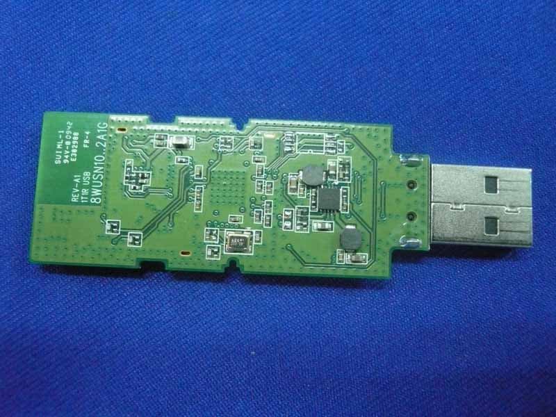
Click to zoom
Application Details
- Equipment Class
- DTS - Digital Transmission System
- Date of Grant
- Apr 20, 2010
- Application Purpose
- Original Equipment
- Date of Application
- Apr 19, 2010
- Equipment Note
- WIRELESS 150 USB ADAPTER
- Frequency Range
- 2422.00000000 - 2452.00000000
- Company
- Alpha Networks Inc.
- Country
- Taiwan
Documents & Files
Document Text
Text extracted from the exhibit documents filed with the FCC. Open a document above to read the original.
Users Manual
Adapter Installation 1. Turn on the computer and Insert the Alpha WUS-N10 Driver CD in the CD-ROM drive 2. When the auto run screen appears, click Install Drivers. The InstallShield Wizard window will appear. 3. By default setup will install to the default location: To install to a different location click Browse and specify the location. 4. Select the Program Files folder location 5. Insert the adapter into an available USB port on your computer. 6. The Wireless Connection Wizard will now appear. 7. To connect to your network using the WPS push button configuration method, click the virtual button as shown in the screenshot. Federal Communication Commission Interference Statement This equipment has been tested and found to comply with the limits for a Class B digital device, pursuant to Part 15 of the FCC Rules. These limits are designed to provide reasonable protection against harmful interference in a residential installation. This equipment generates uses and can radiate radio frequency energy and, if not installed and used in accordance with the instructions, may cause harmful interference to radio communications. However, there is no guarantee that interference will not occur in a particular installation. If this equipment does cause harmful interference to radio or television reception, which can be determined by turning the equipment off and on, the user is encouraged to try to correct the interference by one of the following measures: - Reorient or relocate the receiving antenna. - Increase the separation between the equipment and receiver. - Connect the equipment into an outlet on a circuit different from that to which the receiver is connected. - Consult the dealer or an experienced radio/TV technician for help. This device complies with Part 15 of the FCC Rules. Operation is subject to the following two conditions: (1) This device may not cause harmful interference, and (2) this device must accept any interference received, including interference that may cause undesired operation. FCC Caution: Any changes or modifications not expressly approved by the party responsible for compliance could void the user's authority to operate this equipment. IMPORTANT NOTE: FCC Radiation Exposure Statement: This equipment complies with FCC radiation exposure limits set forth for an uncontrolled environment. End users must follow the specific operating instructions for satisfying RF exposure compliance. IEEE 802.11b or 802.11g operation of this product in the U.S.A. is firmware-limited to channels 1 through 11. Antennas must be installed to provide 20 cm separation distance from the transmitting antenna to the body of the user during normal operating condition. This device must not be co-located or operating in conjunction with any other antenna or transmitter. Only those antennas filed under FCC ID: RRKWUSN10A1 can be used with this device. When the module is installed in the final system where the antenna location is less than 20 cm separation distance to the body of user, additional equipment authorization must be applied. FCC ID label on the final system must be labeled with “Contains FCC ID: RRKWUSN10A1” or “Contains transmitter module FCC ID: RRKWUSN10A1”. In the user guide, final system integrator must be ensure that there is no instruction provided in the user guide to install or remove the transmitter module. The transmitter module must be installed and used in strict accordance with the manufacturer's instructions as described in the user documentation that comes with the product. This device complies with the following radio frequency and safety standards.
Cover Letter(s)
AGENCY AUTHORIZATION LETTER Date: 2010/3/31 To whom it may concern: We, the undersigned, hereby authorize Audix Technology (Shenzhen) Co., Ltd (No. 6, Ke Feng Rd., 52 Block, Shenzhen Science & Industrial Park, Nantou, Shenzhen, Guangdong, China) to act on our behalf, as our agent, in the following matters related to the FCC approval of our products: report submittal, related correspondence, the signing of all documents relating to these matters, and any other lawful activity necessary to obtain such certification. Any act carried out by Audix within the scope of this authorization shall have the same effects as our own. This authorization shall expire 6 months form original date. If you have any Questions regarding the authorization, please don’t hesitate to contact us. Thank you. Sincerely, (Original written signature of authorized signer) ------------------------------------------ Kelly Tsai / Senior Manager Alpha Networks Inc. TEL: 886-3-5636666 FAX: 886-3-5665091 E-mail: [email protected]
Cover Letter(s)
Modular Approval Request Letter Dear Application Examiner, Alpha Networks Inc.,It’s Wireless 150 USB Adapter,FCC ID:RRKWUSN10A1 , would like to have your authorization as a full modular approval specific to the computer device such as desktop/laptop computer. The requirements of section 15.212 have been met and shown on the following statements. 1, “The modular transmitter must have it’s own RF shielding.” The radio portion of this module has been shielded, please see exhibition External Photo. 2, “The modular transmitter must have buffered modulation data inputs.” The EUT has buffered data inputs; it is integrated in chip RT3070. 3,“The modular transmitter must have it’s own power supply regulation.” The USB interface provides 5V DC, the on board power IC UP6381 convert 5V DC to 3.3V and 1.5V DC. 4,“The modular transmitter must comply with antenna requirements of section 15.203 and 15.204(c).” The EUT meets the FCC antenna requirements, it’s have I-PEX antenna connector that no antenna other than that furnished by the responsible party shall be used with the device, the spurious emissions are shown in the test report. 5, “The modular transmitter must be tested in a stand-alone configuration.” The EUT was tested in a stand-alone configuration via a PCB to Notebook, please see section photographs of test configuration in the test report. 6, “The modular transmitter must be labeled with it’s own FCC ID number.” Please see exhibition Label Sample for the FCC ID of this module. 7, “The modular transmitter must comply with any specific rule or operating requirements applicable to the transmitter and the manufacture must provide adequate instructions along with module to explain any such requirement.” The EUT is compliant with all applicable FCC rules, detail instructions for maintaining compliance are given in the users Manual. 8, “The modular transmitter must comply with any applicable RF exposure requirements.” The EUT is compliant with all applicable RF exposure requirements. RF exposure is addressed in the test report. Best Regards, ------------------------------------------ Kelly Tsai / Senior Manager Alpha Networks Inc. TEL: 886-3-5636666 FAX: 886-3-5665091 E-mail: [email protected] 2010/3/31
Cover Letter(s)
For the following information Ref. File No.: C1M1004098 Product : Wireless 150 USB Adapter Model Number : WUS-N10 Applicant : Alpha Networks Inc. Manufacturer : Alpha Networks Inc. Standards : FCC 47 CFR Part 15 Subpart B/Oct 2009 (Class B Limit) and ICES-003 Issue 4 Feb. 2004 We hereby certify that the above product has been tested by us and complied with the FCC official limits. These products might be marketed at the US accordance to FCC Rule based on the standard 47 CFR Part 2 and Part 15 Class B Equipment Regulations. The test was performed accordance to the procedures from ANSI C63.4-2003. The test data & results are issued on the test report no. EM-F990309. Signature _____________________________ Leon Liu/Deputy General Manager Date: Apr. 10, 2010 Test Laboratory: AUDIX Technology Corporation, EMC Department NVLAP Lab. Code: 200077-0 FCC OET Designation: TW1004 Web Site: www.audixtech.com The statement is based on a single evaluation of one sample of the above-mentioned products. It does not imply an assessment of the whole production and does not permit the use of the test lab logo. Lab. Code: 200077-0
Cover Letter(s)
Date: 2010/3/31 Federal Communications Commission Authorization and Evaluation Division FCC ID: RRKWUSN10A1 Confidentiality Request Pursuant to Sections 0.457 and 0.459 of the Commission’s Rules, the Applicant hereby requests confidential treatment of information accompanying this application as outlined below: 1. Block diagram 2. Schematics 3. Operation Description The above materials contain trade secrets and proprietary information not customarily released to the public. The public disclosure of these matters might to harmful to the applicant and provide unjustified benefits to its competitors. The applicant understands that pursuant to Rule 0.457, disclosure of this application and all accompanying documentation will not be made before the date of the grant for this application. Sincerely, (Original written signature of authorized signer) ------------------------------------------ Kelly Tsai / Senior Manager Alpha Networks Inc. TEL: 886-3-5636666 FAX: 886-3-5665091 E-mail: [email protected]
External Photos
FCC ID:RRKWUSN10A1 Page 13-1 Audix Technology (Shenzhen) Co., Ltd. Report No. ACS-F10066 13. PHOTOGRAPH OF EUT Figure 1 General Appearance of the EUT Figure 2 General Appearance of the EUT
ID Label/Location Info
FCC Label and Location
Internal Photos
FCC ID:RRKWUSN10A1 Page 13-1 Audix Technology (Shenzhen) Co., Ltd. Report No. ACS-F10066 13.PHOTOGRAPH OF EUT Figure 1 General Appearance of the EUT Figure 2 General Appearance of the EUT FCC ID:RRKWUSN10A1 Page 13-2 Audix Technology (Shenzhen) Co., Ltd. Report No. ACS-F10066 Figure 3 General Appearance of the EUT
RF Exposure Info
MPE ESTIMATION Limit for General Population/ Uncontrolled Exposures Frequency Power density (mW/ cm 2 ) Averaging time(minutes) 300MHz----1.5GHz F/1500 30 1.5GHz---100GHz1.0 30 Frequency(MHz) Power density (mW/ cm 2 ) Averaging time(minutes) 2412 1 30 2437 1 30 2462 1 30 Note: F= Frequency in MHz Estimation Result Mode CH Frequency (MHz) PK Output power (dBm) Output power (mW) Antenna Gain (dBi) antenna Gain (linear) MPE 11b 1 2412 20.16 103.75 0 1.00 0.0207 6 2437 19.92 98.17 0 1.00 0.0195 11 2462 20.12 102.80 0 1.00 0.0205 11b 1 2412 26.22 418.79 0 1.00 0.0834 6 2437 25.92 390.84 0 1.00 0.0778 11 2462 25.78 378.44 0 1.00 0.0753 11n HT20 1 2412 26.32 428.55 0 1.00 0.0853 6 2437 25.98 396.28 0 1.00 0.0789 11 2462 25.89 388.15 0 1.00 0.0773 11n HT40 1 2422 24.52 283.14 0 1.00 0.0564 4 2437 24.51 282.49 0 1.00 0.0562 7 2452 24.36 272.90 0 1.00 0.0543 Note: The estimation distance is 20cm
Test Report
FCC ID:RRKWUSN10A1 Audix Technology (Shenzhen) Co., Ltd. Report No. ACS-F10066 APPLICATION FOR CERTIFICATION On Behalf of Alpha Network Inc. Wireless 150 USB Adapter Model Number: WUS-N10 FCC ID: RRKWUSN10A1 Prepared for : Alpha Network Inc. NO.8 Li-shing Rd. VII, Science-based Industrial Park, Hsinchu, Taiwan. Prepared By : Audix Technology (Shenzhen) Co., Ltd. No. 6, Ke Feng Rd., 52 Block, Shenzhen Science & Industrial Park, Nantou, Shenzhen, Guangdong, China Tel: (0755) 26639496 Report Number : ACS-F10066 Date of Test : Mar.29~30, 2010 Date of Report : Apr.01, 2010 FCC ID:RRKWUSN10A1 Audix Technology (Shenzhen) Co., Ltd. Report No. ACS-F10066 TABLE OF CONTENTS Description Page 1. SUMMARY OF STANDARDS AND RESULTS................................................................... 1-1 1.1. Description of Standards and Results ............................................................................................1-1 2. GENERAL INFORMATION .................................................................................................. 2-1 2.1. Description of Device (EUT) .........................................................................................................2-1 2.2. Test Information.............................................................................................................................2-2 2.3. Tested Supporting System Details .................................................................................................2-2 2.4. Test Facility ...................................................................................................................................2-3 2.5. Measurement Uncertainty (95% confidence levels, k=2) ..............................................................2-3 3. POWER LINE CONDUCTED EMISSION TEST ................................................................ 3-1 3.1. Test Equipments.............................................................................................................................3-1 3.2. Block Diagram of Test Setup .........................................................................................................3-1 3.3. Power Line Conducted Emission Test Limits................................................................................3-1 3.4. Configuration of EUT on Test .......................................................................................................3-1 3.5. Operating Condition of EUT..........................................................................................................3-2 3.6. Test Procedure................................................................................................................................3-2 3.7. Power Line Conducted Emission Test Results ..............................................................................3-2 4. RADIATED EMISSION TEST ............................................................................................... 4-1 4.1. Test Equipment ..............................................................................................................................4-1 4.2. Block Diagram of Test Setup .........................................................................................................4-1 4.3. Radiated Emission Limit................................................................................................................4-2 4.4. EUT Configuration on Test............................................................................................................4-3 4.5. Operating Condition of EUT..........................................................................................................4-3 4.6. Test Procedure................................................................................................................................4-3 4.7. Radiated Emission Test Results .....................................................................................................4-4 5. CONDUCTED SPURIOUS EMISSIONS............................................................................... 5-1 5.1. Test Equipment ..............................................................................................................................5-1 5.2. Limit...............................................................................................................................................5-1 5.3. Test Procedure................................................................................................................................5-1 5.4. Test result .......................................................................................................................................5-1 6. BAND EDGE COMPLIANCE TEST ..................................................................................... 6-1 6.1. Test Equipment ..............................................................................................................................6-1 6.2. Limit...............................................................................................................................................6-1 6.3. Test Produce ...................................................................................................................................6-1 6.4. Test Results ....................................................................................................................................6-1 7. 6dB Bandwidth Test.................................................................................................................. 7-1 7.1. Test Equipment ..............................................................................................................................7-1 7.2. Limit...............................................................................................................................................7-1 7.3. Test Procedure...........................................................................…
Text truncated - open the document above for the full version.
Test Setup Photos
FCC ID:RRKWUSN10A1 Page 12-1 Audix Technology (Shenzhen) Co., Ltd. Report No. ACS-F10066 12. PHOTOGRAPH OF TEST 12.1.Photos of Power Line Conducted Emission Test FCC ID:RRKWUSN10A1 Page 12-2 Audix Technology (Shenzhen) Co., Ltd. Report No. ACS-F10066 12.2.Photos of Radiated Emission Test (30-1000MHz) FCC ID:RRKWUSN10A1 Page 12-3 Audix Technology (Shenzhen) Co., Ltd. Report No. ACS-F10066 (Above 1000MHz)
Contact Information
Applicant
Kelly Tsai(Director)
Test Firm
Audix Technology ( Shanghai ) Co., Ltd.Byron Kwo
Technical Specifications
| # | Rule Parts | Frequency Range | Power Output |
|---|---|---|---|
| 2 | 15C | 2.42 GHz - 2.45 GHz | 283.00 mW |
Other Applications from Alpha Networks Inc.
RRK-MSSS2571
Jul 22, 2026Z-Wave 800 module
Equipment Class
DTS - Digital Transmission SystemRRK-W1700A3
Jul 22, 2026Wi-Fi 7 Router
Equipment Class
6ID - 15E 6 GHz Low Power Indoor Access Point
RRK-BW1600A
Oct 10, 2023LTE Data and Voice (ATA) In-Home Gateway
Equipment Class
NII - Unlicensed National Information Infrastructure TX
RRK-ARSSM01
Feb 08, 202179G Radar
Equipment Class
VRD - Part 95 Vehicular Radar Systems
RRK-ARSSA07
Feb 08, 2021Radar (UART), Radar (CAN)
Equipment Class
VRD - Part 95 Vehicular Radar Systems