RS6BT-4A-CK-CKSBLUETOOTH HEADSET/HANDFREE KIT
Halfa Enterprise Co.,Ltd.
Click to zoom
Application Details
- Equipment Class
- DSS - Part 15 Spread Spectrum Transmitter
- Date of Grant
- Mar 11, 2004
- Application Purpose
- Original Equipment
- Date of Application
- Mar 11, 2004
- Equipment Note
- BLUETOOTH HEADSET/HANDFREE KIT
- Frequency Range
- 2402.00000000 - 2480.00000000
- Company
- Halfa Enterprise Co.,Ltd.
- Country
- Taiwan
Documents & Files
Document Text
Text extracted from the exhibit documents filed with the FCC. Open a document above to read the original.
Users Manual
BT-CK USER MANUAL Accessories A.Headset B. Control Base C. Pouch(Optional) D. Cigarette Cable for DC plug E.Speaker and Its accessories F.Interchangeable DC Adapter(Optional) G.3M Double Side Tape H. Interchangeable Adapter for Headset (Optional) I. USB Retractable Cable (Optional) J. USB AC Adapter-US Type(Optional) K.USB AC Adapter-EU Type(Optional) L. Spring Plate(Optional). INSTALLATION for car use 1. Position the Control Base on the right position of dashboard by 3M double side tape or clip on the sun visor by Spring Plate. 2. Plug the DC PLUG of the Power Cable and PHONE PLUG of the external speaker into the jack on the CONTROL BASE (see the picture as below). 3. Plugging the cigarette plug of the Charging Cable into cigarette lighter for power source (in car use). INSTALLATION for indoor use 1. Position the Control Base on the right position inside your room or office. 2. Clip the CONTROL BASE on the proper position inside your room or office or release the clip from the Control Base for putting the Control Base on the desk. 3. Plug the DC PLUG of the Power Cable and PHONE PLUG of the external speaker into the jacks B and A on the CONTROL BASE (see the picture as below). - 1 - A. Jack for speaker B. DC Power Inlet 4. Plugging the USB AC Adapter into the inlet of AC power source on the wall while use indoors.. Remark: Please keep the external speaker at least 80cm away from the Control Base. TURN THE UNIT ON/OFF HEADSET ON: zTake the headset from the CONTROL BASE, pressing down the multifunction button for 2 seconds. The BT-4A headset will turn ON. When it is ON, a low-high tone is heard and a continuous green light indicator A will be on. After releasing the multifunction button, the light will blink that indicates the unit is waiting for a callstandby mode. zIf the indicator B turns red, it means that the battery on the headset is low. RE-CHARGE THE HEADSET immediately by putting it back to the CONTROL BASE dock for charging. HEADSET OFF: zPressing the multifunction button for about 2 seconds will turn it OFF. A high-low tone will be heard and the indicator lights will be off. Turning off the headset is necessary to conserve battery life if the headset will not be used for a long time. PAIRING TO THE PHONE zBefore use, the headset MUST BE PAIRED with the phone. Pairing needs to be done only once. When the phone and the unit have been paired, connecting to the phone will be automatic every time the phone is used. Enter into Pairing Mode aThis unit is first set under stand-by mode –Indicator A blinks every 4 seconds. bTo enter into pairing mode, (1) First, set this unit under OFF mode.To enter into OFF mode, please press the function key for 2 seconds until Indicator A is off. A short beep will sound if it is off. (2) Press function key for 4 secondsapprox.until Indicator - 2 - A is on & Indicator B is blinking. Meanwhile, two beeps Come after and the Headset is in “Headset” mode. (3) Press function key again (while in headset mode) until two beeps coming, the Indicator A & B will be distinguished very shortly. Then the Indicator A (green) is on & Indicator B (red) is blinking and the mode is in “car” mode. ANSWERING/RECEIVING A CALL VIA BT-CK CAR KIT zSimply dock the headset on the control unit as a car kit with mute function. When phone is receiving a call, the phone ring tone will be heard via the speaker; you need only to press the multifunction button on the headset once to answer the call. Pressing the button again will automatically hang-up and terminate the call MAKING A CALL (VOICE DIALING) Calling through the headset of the BT-CK car kit can be done by using voice dialing. The steps are: zPress the headset button to activate the voice dialing. zA beep will then be heard prompting the user to say the name of the person to call. zSay the name. zThe phone will then place the call automatically. In case the phone does not recognize the name spoken, the steps above may be repeated. zPress the headset button again to terminate the call. zIf the desired number to be dialed has no voice tag, normal dialing can also be done using the keypad on the Bluetooth phone. When connected, pressing the button of the headset will hang-up and terminate the call. SETTING THE VOLUME Rotate the potentiometer in clockwise direction , it means volume up In counterclockwise means volume down PRIVATE CONVERSATION Simply take the headset from the Control Base and wear it on your ear for private conversation. The conversation can continue with interruption even though you leave your car for office or home. CHARGING Simply dock the headset on the Control Base. (See picture below). While in charging condition, the red light indicator will be on continuously. When the red indicator goes off, it means the unit is completely charged. - 3 - Power Indicator (Red) Control Base Power Inlet Indicator A (Green) Indicator B (Red) Volume Up ( + ) Volume Down ( - ) Ear Hook Multifunction Button (function key) Talk/Hang-up/Voice Dial/Power On-Off Bluetooth Headset and BT-CK Control Base Flange DC Jack for 5.1V Fillisters Hook Bottom view of the main unit - 4 - Put the fillisters of the ear hook into the flange of the main unit and keep alignment as the picture shown. For wearing on left ear For wearing on right ear Charging Plug Power indicator Audio Input Rotate the ear hook to the proper position as the picture shown above. Volume Control DC Jack for 12V CONTROL BASE Headset is docked at Control Base . INSTRUCTION –ERICSSON PHONES: Enter into Pairing Mode aThis unit is first set under stand-by mode –Indicator A blinks every 4 seconds. bTo enter into pairing mode, (1) First, set this unit under OFF mode.To enter into OFF mode, please press the function key for 2 seconds until Indicator A is off. A short beep will sound if it is off. (2) Press function key for 4 secondsapprox.until Indicator A & Indicator B (red green LEDS) blink in turn. Meanwhile, a short beep will sound. Pairing Between Phones and Headset aInitia…
Text truncated - open the document above for the full version.
Cover Letter(s)
Halfa Enterprise Co., Ltd. Jan.09.2004 Federal Communications Commission Authorization and Evaluation Division FCC IDRS6BT-4A-CK-CKS Confidentiality Request Pursuant to Sections 0..457 and 0.459 of the Commission’s Rules, the Applicant Hereby requests confidential treatment of information accomparrting this Application As outlined below: 1. Block Diagram, 2. Schematic Diagram, The above materials contain trade secrets and proprietary information not customarily Released to the public. The public disclosure of these matters might be harmful to the Applicant and provide unjustified benefits to its competitors. The Applicant understands that pursuant to Rule 0.457, disclosure of this Application and all accompanying documentation will not be made before the date of the Grant for this application Sincerely, Johnny Yen / R&D Manager Applicant: Halfa Enterprise Co., ltd. ADDRESS: 5F,No.102, Ming Chuan Road, Hsin Tien, Taipei, Taiwan 231 R.O.C TEL: 886-2-2219-7929 FAX: 886-2-2219-7931
External Photos
FCC TEST REPORT REPORT NO. : F392411 APPENDIX A. Photographs of EUT SPORTON International Inc. PAGE NUMBER : A1 OF A7 TEL : 886-2-2696-2468 ISSUED DATE : Dec. 25, 2003 FAX : 886-2-2696-2255 FCC TEST REPORT REPORT NO. : F392411 SPORTON International Inc. PAGE NUMBER : A2 OF A7 TEL : 886-2-2696-2468 ISSUED DATE : Dec. 25, 2003 FAX : 886-2-2696-2255 FCC TEST REPORT REPORT NO. : F392411 SPORTON International Inc. PAGE NUMBER : A3 OF A8 TEL : 886-2-2696-2468 ISSUED DATE : Dec. 25, 2003 FAX : 886-2-2696-2255 FCC TEST REPORT REPORT NO. : F392411 SPORTON International Inc. PAGE NUMBER : A4 OF A7 TEL : 886-2-2696-2468 ISSUED DATE : Dec. 25, 2003 FAX : 886-2-2696-2255 FCC TEST REPORT REPORT NO. : F392411 SPORTON International Inc. PAGE NUMBER : A5 OF A8 TEL : 886-2-2696-2468 ISSUED DATE : Dec. 25, 2003 FAX : 886-2-2696-2255 FCC TEST REPORT REPORT NO. : F392411 SPORTON International Inc. PAGE NUMBER : A6 OF A8 TEL : 886-2-2696-2468 ISSUED DATE : Dec. 25, 2003 FAX : 886-2-2696-2255 FCC TEST REPORT REPORT NO. : F392411 SPORTON International Inc. PAGE NUMBER : A7 OF A8 TEL : 886-2-2696-2468 ISSUED DATE : Dec. 25, 2003 FAX : 886-2-2696-2255 FCC TEST REPORT REPORT NO. : F392411 SPORTON International Inc. PAGE NUMBER : A8 OF A9 TEL : 886-2-2696-2468 ISSUED DATE : Dec. 25, 2003 FAX : 886-2-2696-2255
ID Label/Location Info
FCC ID: RS6BT-4A-CK-CKS Label Location
Operational Description
FCC ID: RS6BT-4A-CK-CKS Model:BT-4A Model: BT-CK
Test Report
FCC ID: RS6BT-4A-CK-CKS Issued on Feb. 17, 2004 Report No.: F392411 SPORTON International Inc. TEL : 886-2-2696-2468 FCC TEST REPORT CATEGORY: Outdoor Mobile End Product PRODUCT NAME: Bluetooth headset/handfree kit FCC ID.: RS6BT-4A-CK-CKS FILING TYPE: Certification BRAND NAME: Halfa MODEL NAME: BT-4A, BT-CKS, BT-CK APPLICANT: Halfa Enterprise Co., Ltd. 5F, No. 102, Ming Chuan Road, Hsin Tien, Taipei, Taiwan 231, R.O.C. MANUFACTURER: The same as Applicant. ISSUED BY: SPORTON INTERNATIONAL INC. 6F, No. 106, Sec. 1, Hsin Tai Wu Rd., His Chih, Taipei Hsien, Taiwan, R.O.C. Statements: The test result in this report refers exclusively to the presented test model / sample. Without written approval of SPORTON International Inc., the test report shall not be reproduced except in full. Certificate or Test Report could not be used by the applicant to claim the product endorsement by CNLA, NVLAP or any agency of U.S. government. The test equipment used to perform the test are calibrated and traceable to NML/ROC or NIST/USA. Lab Code: 200079-0 FAX : 886-2-2696-2255 FCC ID: RS6BT-4A-CK-CKS Issued on Feb. 17, 2004 Report No.: F392411 Table of Contents History of this test report.....................................................................................................ii 1. General Description of Equipment under Test...............................................................1 1.1. General Description.........................................................................................................................................................................1 1.2. List of EUT Accessories..................................................................................................................................................................1 1.3. Technical Features..........................................................................................................................................................................1 2. TEST CONFIGURATION OF THE EQUIPMENT UNDER TEST........................................3 2.1. Description of the Test....................................................................................................................................................................3 2.2. Frequency Range Investigated.......................................................................................................................................................3 2.3. Details of the Supporting Units........................................................................................................................................................4 2.4. Connection Diagram of Test System..............................................................................................................................................4 3. TEST SOFTWARE..............................................................................................................5 4. TEST LOCATION AND STANDARDS...............................................................................6 4.1. Test Location...................................................................................................................................................................................6 4.2. Test Standards................................................................................................................................................................................6 4.3. DoC Statement................................................................................................................................................................................6 5. TEST RESULT AND DETAILS...........................................................................................7 5.1. Summary of the Test Results..........................................................................................................................................................7 5.2. Hopping Channel Bandwidth...........................................................................................................................................................8 5.3. Number of Hopping Frequency.....................................................................................................................................................11 5.4. Hopping Channel Separation........................................................................................................................................................13 5.5. Dwell Time of Each Frequency within a 30 Seconds Period.........................................................................................................16 5.6. Output Power................................................................................................................................................................................19 5.7. 100KHz Bandwidth of Frequency Band Edges.............................................................................................................................22 5.8. Conducted Emission.....................................................................................................................................................................26 5.9. Test of Radiated Emission............................................................................................................................................................30 5.10.Antenna Requirements.................................................................................................................................................................42 5.11.RF Exposure.................................................................................................................................................................................43 6. List of Measuring Equipments Used.............................................................................45 Appendix A. Photographs of EUT..................................…
Text truncated - open the document above for the full version.
Test Setup Photos
Photographs of Conducted Emission Test Configuration z The photographs show the configuration that generates the maximum emission. <Mode 1~6> FRONT VIEW REAR VIEW SIDE VIEW <Mode 7~9> FRONT VIEW REAR VIEW SIDE VIEW
Contact Information
Applicant
Charles Hong(President)
Test Firm
SPORTON International IncKathy Lin
Technical Specifications
| # | Rule Parts | Frequency Range | Power Output |
|---|---|---|---|
| 1 | 15C | 2.40 GHz - 2.48 GHz | 2.24 mW |
Other Applications from Halfa Enterprise Co.,Ltd.
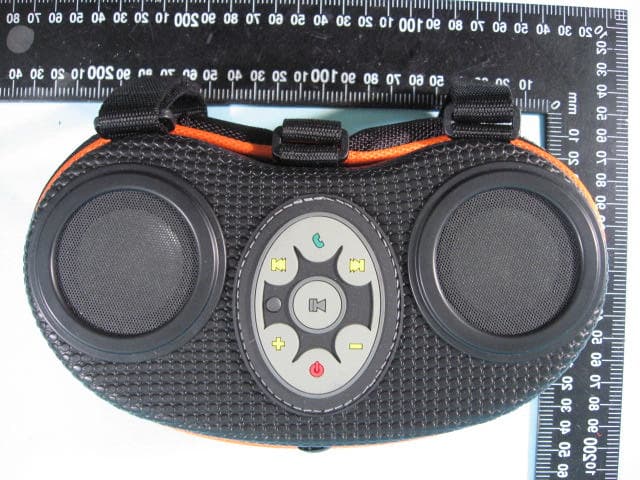
RS6BOOMBOX88E
Sep 13, 2010Bluetooth Boom Box
Equipment Class
DSS - Part 15 Spread Spectrum Transmitter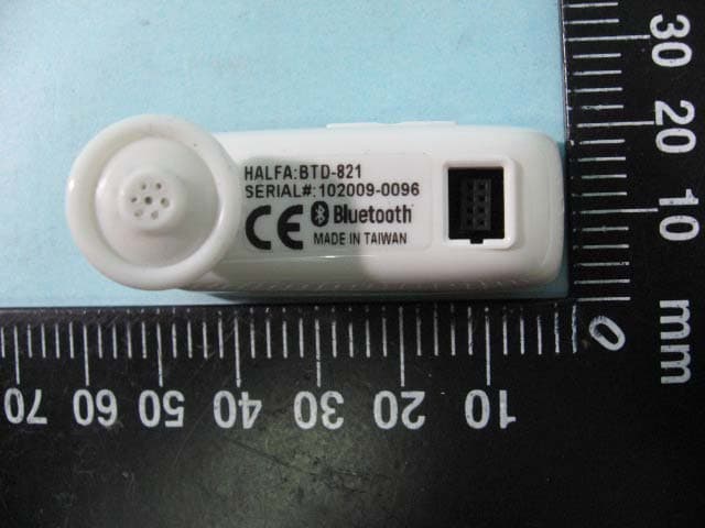
RS6IDOCK12BTD821
Mar 10, 2010iDock-12 Bluetooth Conference Combo Kit
Equipment Class
DSS - Part 15 Spread Spectrum Transmitter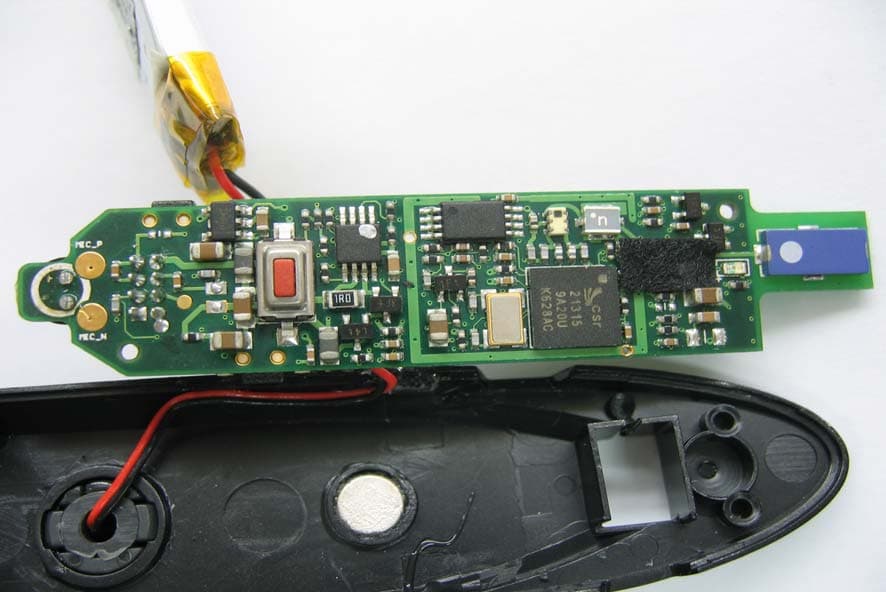
RS6BTD621CKDTSP
Apr 23, 2007BLUETOOTH HEADSET
Equipment Class
DSS - Part 15 Spread Spectrum Transmitter