RS6IDOCK12BTD821iDock-12 Bluetooth Conference Combo Kit
Halfa Enterprise Co.,Ltd.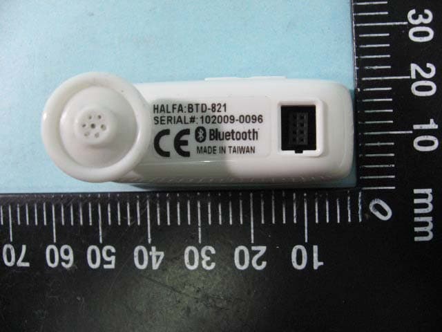
Click to zoom
Application Details
- Equipment Class
- DSS - Part 15 Spread Spectrum Transmitter
- Date of Grant
- Mar 10, 2010
- Application Purpose
- Original Equipment
- Date of Application
- Mar 10, 2010
- Equipment Note
- iDock-12 Bluetooth Conference Combo Kit
- Frequency Range
- 2402.00000000 - 2480.00000000
- Company
- Halfa Enterprise Co.,Ltd.
- Country
- Taiwan
Documents & Files
Document Text
Text extracted from the exhibit documents filed with the FCC. Open a document above to read the original.
Users Manual
1. Please fully charge the batt ery of the Headset and the Docking Base for approximately 6 hours before initial use. 2. Pair the headset with a Bluetooth-enabled mobile phone. 3. Adjust the volume to a pref er red listening level by adjusting volume on the headset, the docking base and the mobile phone. 4. For optimal sound quality when using speakerphone, we recommend the range between user and microphone not to exceed 12 inches. Note: If the multifunction button is not responding or headset is not working, please reset by inserting a thin it em into the reset hole . The docking base and headset can be charged together or separately, using the included car adapter or USB charging cable. Additionally, the docking base can recharge the headset without any external power source. 1. Connect the charging cable to the headset or connect the USB cable to charge the docking base or headset with docking base. 2. Dock the headset into the docking base if you wish to charge the headset without the USB cable. Switch the charging switch on the Side of the docking base. 3. Connect to other end of the charging cable to the car adapter or the USB port of your PC. Charging is indicated by a Sta tus LED (red) on the docking base or the Indicator A (red) on the headset. 4. Allow the headset and/or docking base to Before use, the headset must be paired with the mobile phone. The pairing procedure only needs to be done once. To pair the headset to a mobile phone mode. 2. Ensure the Bluetooth radio on your mobile phone is power ed on. Please ref er to the phone user manual for details. 3. Hold the multifunction button on the headset for 8 seconds. the Indicator A, B will blink once, blue. The headset is ready to pair. 4. Set the mobile phone to search for Bluetooth devices and follow the instructions on the phone’s screen. Please ref er to the phone user manual for details. You will recognize the headset by its Bluetooth name ”iDock-12”. 5. Select the ”iDock-12” f or pairing. When prompted for a passkey, enter “1234”. 6. Within a few seconds connection is complete Note: A warning tone is heard when the paired and connected cellular phone is out of service. charge completely. Charging is complete when the LED is dimmed. when you are not using it to conserve batt ery power. 2. It may have charging buzz while the headset is charging during converstion. 3. The Mini USB cable is for power charging only, it will not provide data transfer function while connected to your PC. Headset On 1. Hold the multifunction button to turn ON your headset. 2. A low-high tone is heard and the Indicator A, B will blink once. 3. After releasing the multifunction button the Indicator B (blue LED) r apidly blinks every few seconds indicating that the unit is in standby mode. red and tone sounds every 30 seconds, the headset batt ery is low. Re-charge the headset immediately. (Please refer to Charging section) 1. Press the multifunction button for 3 seconds to 2. A high-low tone is heard and the Indicator A, B will blink once. for power saving when the Bluetooth is not connected. CHARGING GETTING STARTED TURN ON/OFF THE BLUETOOTH HEADSET PAIRING TO A MOBILE PHONE iDock-12 User Manual 1. Install the Metal Clip into the Docking Base. 2. Install the Docking Base under the Sun Visor. 3. Dock the headset into the docking base 4. The closer you speak to the microphone, the clearer your voice will be to the other party. 5. Adjust the volume to your preferred listening level. 1. During the conversation, unplug the headset from the docking base and plug into either right or left ear for private conversation. 2. You can also attach the ear hook on the headset, and place it on your left or right ear. Reset the Headset Use a stick (diameter less than 1.6 mm) insert into the reset hole at the right side of the headset to make reset. Answering a call 1. Press the multifunction button briefly and release. Call is answered. 2. Press the button again to end the call. Reject a call Hold the multifunction button for 2 seconds. Call is rejected. Make a call You may make a call in the normal way and press SEND, or use voice dialing if your mobile phone supports it and is properly set up. Please refer to your mobile phone user manual for voice dial set up detail. Activate voice dialing (Dependent on your phone supporting) 1. Press the headset multifunction button to activate the voice dialing. 2. A beep will be heard then prompting the user to say the name of the person to call. 3. The phone will place the call automatically. In case the phone does not recognize the name spoken, the steps above may be repeated. 4. Press the button again to end the call Last Call Redial (Dependent on your phone supporting) 1. Unplug the headset from the Docking Base and hold down the volume down(-) button for 2 seconds 2. Release after a low-high. The redial will be in process. Hold Function (Dependent on your phone supporting) 1. Hold the volume down (-) button for 2 seconds to put the active call on hold. 2. Hold the volume down (-) button again for 2 seconds to switch back to the call. Mute Function (Dependent on your phone supporting) 1. Simultaneously press both the volume down (-) and up (+) buttons to enable the mute function 2. Press both buttons again to disable the mute function. Transfer Function (Dependent on your phone supporting) 1. Hold the volume up (+) button for 2 seconds to transfer the call from headset to phone. 2. Hold the volume up (+) button for 2 seconds again to transfer the call back to the headset. SAFETY AND APPROVALS AND CERTIFICATION Users are advised not to make changes or modify the device in any way. Changes or modifications not expressly approved by Halfa will void the warranty. FCC Notices This device complies with part 15 of the FCC rules. Operation is subject to the following two conditions: (1)This device may not cause harmful interference, and (2)This device must accept any interference received, including interference that may cause…
Text truncated - open the document above for the full version.
External Photos
ETC Report No. : 10-01-RBF-138-01 FCC ID.: RS6IDOCK12BTD821 Sheet 1 of 5 Sheets Rev. No 2.1 CONSTRUCTED PHOTOS of EUT 1. Top View of EUT 2. Bottom View of EUT ETC Report No. : 10-01-RBF-138-01 FCC ID.: RS6IDOCK12BTD821 Sheet 2 of 5 Sheets Rev. No 2.1 CONSTRUCTED PHOTOS of EUT 3. Side View of EUT 4. Side View of EUT ETC Report No. : 10-01-RBF-138-01 FCC ID.: RS6IDOCK12BTD821 Sheet 3 of 5 Sheets Rev. No 2.1 CONSTRUCTED PHOTOS of EUT 5. Side View of EUT
ID Label/Location Info
910805 1 LABEL 32mm 22mm HaIfa Enterprise Co.,Ltd. Model :BTD-821 FCC ID :RS6IDOCK12BTD821
Internal Photos
ETC Report No. : 10-01-RBF-138-01 FCC ID.: RS6IDOCK12BTD821 Sheet 4 of 5 Sheets Rev. No 2.1 CONSTRUCTED PHOTOS of EUT 6. Internal View of EUT 7. Internal View of EUT ETC Report No. : 10-01-RBF-138-01 FCC ID.: RSIDOCK12BTD821 Sheet 5 of 5 Sheets Rev. No 2.1 CONSTRUCTED PHOTOS of EUT 8. Component View of PCB 9. Solder View of PCB
Parts List/Tune Up Info
ACX Advanced Ceramic X Features Monolithic SMD with small, low-profile and light-weight type. Wide bandwidth Applications 2.4GHz WLAN, Home RF, Bluetooth Modules, etc. Specifications Part Number Frequency Range (MHz) Peak Gain (dBi typ.) Average Gain (dBi typ.) VSWR Impedance AT8010 -E2R9HAA_ 2400~2500 2.5 (XZ-V) 0.5 (XZ-V) 2 max. 50 Ω Q’ty/Reel (pcs) : 1,000 pcs Operating Temperature Range : -40 ~ +85 o C Storage Temperature Range : +5 ~ +35 o C, Humidity 45~75%RH Storage Period : 12 months max. Power Capacity : 2W max. Part Number c Type AT : Antenna d Dimensions ( L × W ) 8.0 × 1.0 mm e Material Code E f Frequency Range 2R9=2900MHz g Specification Code HAA h Packaging T: Tape & Reel B: Bulk Terminal Configuration No. Terminal Name No. Terminal Name c Feeding Point d NC AT8010 Series Multilayer Chip Antenna AT 8010 - E 2R9 HAA c d e fhg c d KAUSHENG ELECTRONICS CO.,LTD. TEL:886-2-8522-7008 FAX:886-2-8522-7009 www.kaushen g.com.tw ACX Advanced Ceramic X Dimensions and Recommended PC Board Pattern Mark L W T a1 a2 Dimensions 8.00.2 1.00.2 1.00.2 0.50.2 1.00.2 The Recommended PC Board layout – Type A With Matching Circuits (Unit in mm) *Line width should be designed to match 50Ω characteristic impedance, depending on PCB material and thickness. Unit : mm L W a1 T a2 (Matching circuit and component values will be different, depending on PCB layout) 1 1.5 7 1 1 2.7 nH 1 pF Ground No Ground Feeding line KAUSHENG ELECTRONICS CO.,LTD. TEL:886-2-8522-7008 FAX:886-2-8522-7009 www.kaushen g.com.tw ACX Advanced Ceramic X Typical Electrical Characteristics (T=25 o C) Test Board – Type A (Unit in mm) Return Loss / With Matching Circuits 40 No Ground Antenna 12 20 Ground Matching circuits Feeding line KAUSHENG ELECTRONICS CO.,LTD. TEL:886-2-8522-7008 FAX:886-2-8522-7009 www.kaushen g.com.tw ACX Advanced Ceramic X Radiation Patterns XZ cut @2.45GHz Vertical Horizontal YZ cut @2.45GHz Vertical Horizontal XZ-V/XZ-H YZ-V/YZ-H XY cut @2.45GHz Vertical Horizontal XY-V/XY-H 180 o 270 o 0 o 90 o X Z Y XY-cut scanning direction 180 o 270 o 0 o 90 o X Z Y XZ-cut scanning direction 180 o 270 o 0 o 90 o X Z Y YZ-cut scanning direction KAUSHENG ELECTRONICS CO.,LTD. TEL:886-2-8522-7008 FAX:886-2-8522-7009 www.kaushen g.com.tw ACX Advanced Ceramic X The Recommended PC Board layout – Type B With Matching Circuits (Unit in mm) *Line width should be designed to match 50Ω characteristic impedance, depending on PCB material and thickness. (Matching circuit and component values will be different, depending on PCB layout) 1.8 1.5 7 1 1 1.8 pF 1.5 nH Ground No Ground Feeding line 1 KAUSHENG ELECTRONICS CO.,LTD. TEL:886-2-8522-7008 FAX:886-2-8522-7009 www.kaushen g.com.tw ACX Advanced Ceramic X Typical Electrical Characteristics (T=25 o C) Test Board – Type B (Unit in mm) Return Loss / With Matching Circuits 52 No Groun d Antenna 20 Ground Matching circuits Feeding line 10.7 4.0 KAUSHENG ELECTRONICS CO.,LTD. TEL:886-2-8522-7008 FAX:886-2-8522-7009 www.kaushen g.com.tw ACX Advanced Ceramic X Radiation Patterns XZ cut @2.45GHz Vertical Horizontal YZ cut @2.45GHz Vertical Horizontal XZ-V/XZ-H YZ-V/YZ-H XY cut @2.45GHz Vertical Horizontal XY-V/XY-H 180 o 270 o 0 o 90 o X Z Y XY-cut scanning direction 180 o 270 o 0 o 90 o X Z Y XZ-cut scanning direction 180 o 270 o 0 o 90 o X Z Y YZ-cut scanning direction KAUSHENG ELECTRONICS CO.,LTD. TEL:886-2-8522-7008 FAX:886-2-8522-7009 www.kaushen g.com.tw
Test Report
Rev. No 1.0 FCC Part 15 EMI TEST REPORT of E.U.T. : iDock-12 Bluetooth Conference Combo Kit Model : BTD-821 FCC ID : RS6IDOCK12BTD821 for APPLICANT : Halfa Enterprise Co., Ltd. ADDRESS : 5F No. 102 MING CHUAN RD, HSINTIEN CITY, TAIPEI COUNTY, TAIWAN Test Performed by ELECTRONICS TESTING CENTER, TAIWAN NO.34, LIN 5, DINGFU TSUEN, LINKOU SHIANG TAIPEI COUNTY, TAIWAN, 24442, R.O.C. Tel:(02)26023052 Fax:(02)26010910 http://www.etc.org.tw ; e-mail : [email protected] Report Number : 10-01-RBF-138-01 ETC Report No. : 10-01-RBF-138-01 FCC ID.: RS6IDOCK12BTD821 Rev. No 1.1 TEST REPORT CERTIFICATION Applicant : Halfa Enterprise Co., Ltd. 5F No. 102 MING CHUAN RD, HSINTIEN CITY, TAIPEI COUNTY, TAIWAN Manufacture : Halfa Enterprise Co., Ltd. 5F No. 102 MING CHUAN RD, HSINTIEN CITY, TAIPEI COUNTY, TAIWAN Description of Device : a) Type of EUT : iDock-12 Bluetooth Conference Combo Kit b) Trade Name : Halfa c) Model No. : BTD-821 d) Power : Earphone: DC 3.7V 85mAh Charger: DC 3.7V 570mAh Regulation Applied : FCC Rules and Regulations Part 15 Subpart C (2008) I HEREBY CERTIFY THAT: The data shown in this report were made in accordance with the procedures given in ANSI C63.4(2003), and the energy emitted by the device was founded to be within the limits applicable. I assume full responsibility for accuracy and completeness of these data. Note: 1. The result of the testing report relate only to the item tested. 2. The testing report shall not be reproduced expect in full, without the written approval of ETC. ETC Report No. : 10-01-RBF-138-01 FCC ID.: RS6IDOCK12BTD821 Rev. No 1.1 Date Test Item Received : Jan. 26, 2010 Date Test Campaign Completed : Feb. 02, 2010 Date of Issue : Feb. 03, 2010 Test Engineer : ( Vincent Chang, Engineer ) Check By : ( Charles Wang, Supervisor ) Approve & Authorized : Will Yauo, Manager EMC Dept. II of ELECTRONICS TESTING CENTER, TAIWAN ETC Report No. : 10-01-RBF-138-01 FCC ID.: RS6IDOCK12BTD821 Rev. No 1.1 Table of Contents Page 1 GENERAL INFORMATION ...................................................................................................... 1 1.1 Product Description...................................................................................................................... 1 1.2 Test Methodology ........................................................................................................................ 1 1.3 Test Facility.................................................................................................................................. 1 2 PROVISIONS APPLICABLE ..................................................................................................... 2 2.1 Definition ..................................................................................................................................... 2 2.2 Requirement for Compliance ....................................................................................................... 3 2.3 Restricted Bands of Operation ..................................................................................................... 5 2.4 Labeling Requirement .................................................................................................................. 6 2.5 User Information .......................................................................................................................... 6 3 SYSTEM TEST CONFIGURATION ......................................................................................... 7 3.1 Justification .................................................................................................................................. 7 3.2 Devices for Tested System........................................................................................................... 7 4 RADIATED EMISSION MEASUREMENT ............................................................................. 8 4.1 Applicable Standard ..................................................................................................................... 8 4.2 Measurement Procedure............................................................................................................... 8 4.3 Measuring Instrument ................................................................................................................ 10 4.4 Radiated Emission Data ............................................................................................................. 11 4.5 Field Strength Calculation.......................................................................................................... 16 4.6 Photos of Radiation Measuring Setup........................................................................................ 17 5 CONDUCTED EMISSION MEASUREMENT ....................................................................... 19 5.1 Description ................................................................................................................................. 19 6 ANTENNA REQUIREMENT ................................................................................................... 20 6.1 Standard Applicable ................................................................................................................... 20 6.2 Antenna Construction................................................................................................................. 20 7 HOPPING CHANNEL SEPARATION .................................................................................... 21 7.1 Standard Applicable ................................................................................................................... 21 7.2 Measurement Procedure............................................................................................................. 21 7.3 Measurement Equipment ........................................................................................................... 22 7.4 Measurement Data .........................................…
Text truncated - open the document above for the full version.
Test Setup Photos
ETC Report No. : 10-01-RBF-138-01 FCC ID.: RS6IDOCK12BTD821 Sheet 17 of 62 Sheets Rev. No 2.1 4.6 Photos of Radiation Measuring Setup BT mode ETC Report No. : 10-01-RBF-138-01 FCC ID.: RS6IDOCK12BTD821 Sheet 18 of 62 Sheets Rev. No 2.1 Charging mode
Contact Information
Applicant
Charles Hong(President)
Test Firm
Electronics Testing Center, TaiwanWill Yauo
Technical Specifications
| # | Rule Parts | Frequency Range | Power Output |
|---|---|---|---|
| 1 | 15C | 2.40 GHz - 2.48 GHz | 1.00 mW |
Other Applications from Halfa Enterprise Co.,Ltd.
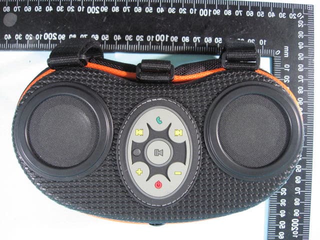
RS6BOOMBOX88E
Sep 13, 2010Bluetooth Boom Box
Equipment Class
DSS - Part 15 Spread Spectrum Transmitter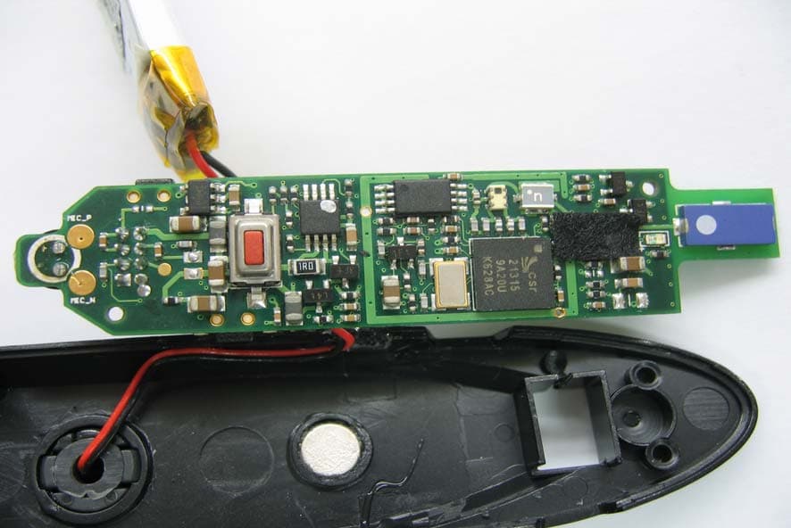
RS6BTD621CKDTSP
Apr 23, 2007BLUETOOTH HEADSET
Equipment Class
DSS - Part 15 Spread Spectrum Transmitter
RS6BT-4A-CK-CKS
Mar 11, 2004BLUETOOTH HEADSET/HANDFREE KIT
Equipment Class
DSS - Part 15 Spread Spectrum Transmitter