RSD-50418RX2.4G Helicopter
Interactive Toy Concepts Limited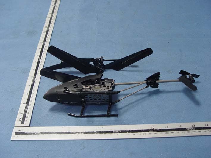
Click to zoom
Application Details
- Equipment Class
- DXX - Part 15 Low Power Communication Device Transmitter
- Date of Grant
- Apr 24, 2014
- Application Purpose
- Original Equipment
- Date of Application
- Apr 23, 2014
- Equipment Note
- 2.4G Helicopter
- Frequency Range
- 2414.00000000 - 2473.00000000
- Country
- Hong Kong
Documents & Files
Document Text
Text extracted from the exhibit documents filed with the FCC. Open a document above to read the original.
Users Manual
The transmitter is a digital proportional radio, therefore small movements in the control sticks produce precise control.ON / OFF SWITCH - Turns the transmitter ON and OFF. LED - Turns on when the transmitter is on. PRO / NORMAL SWITCH - In normal mode, the helicopter will fly forward and backward, and turn left and right at normal speed. In Pro mode the helicopter will fly forward and backward, and turn left and right with a faster speed.LEFT STICK - UP / DOWN - Controls the altitude/throttle. The further you push the left stick up, the higher the helicopter will fly. RIGHT STICK - UP / DOWN - Controls the forward/backward movement and speed of the helicopter. Move the stick away from you - the helicopter flies forward. Move the stick towards you - the helicopter flies backwards.RIGHT STICK - LEFT / RIGHT - Controls left/right steering direction of the helicopter. Move the stick to the left to turn the helicopter to the left.Move the stick to the right to turn the helicopter to the right. As the Triumph helicopter is flying towards you, you will naturally experience a phenomenon called “Control Reversal”. Thus moving the right stick to the right will make the helicopter fly to your left side. Moving the right stick to the left wil l make the helicopter fly to your right side. ATTENTION:Check the condition of all the rotor blades prior to each flight. Do not try to operate the Triumph helicopter if any rotor bla de has been damaged. Broken or damaged rotor blades may have sharp edges or corners and they will be spinning fast with a potential for injury! Flying the Triumph helicopter with broken rotor blades can also make the helicopter fly in an unstable or uncontrollable manner. This may cause damage to furniture and other property, as well as injury to plants, animals and people. Broken rotor blades can be easily replaced as described in the “REPLACING DAMAGED ROTOR BLADES” section below.1. Insert Antenna into controller and turn it until it is securely in place.2. Extend Transmitter Antenna.3. Turn on the Transmitter.4. Select either the normal mode or the pro mode on the Transmitter by sliding the Pro/Normal switch to the desired setting. In normal mode, the helicopter will fly forward and backward, and turn left and right at normal speed. In Pro mode the helicopter will fly forward and backward, and turn left and right with a faster speed. Normal mode is recommended for beginners and intermediate users, while Pro mode is recommended for advanced users.5. Turn on the fully charged helicopter. Note, the red LED at the bottom front of the helicopter will turn on.6. Set helicopter on a horizontal flat surface for the best take off.7. Push left stick (UP / DOWN) completely to UP, then back to DOWN to initialize the radio link between the transmitter and the helicopter.8. Gently push the right stick (UP / DOWN - throttle) up to increase the throttle and ensure that the rotors start spinning. No w that you know your helicopter is functioning as it should - RELAX! -DO NOT TAKE OFF! Be sure to read the next section on "FIRST FLIGHT - TRIMMING YOUR HELICOPTER" before your first flight! GET IN THE AIR FAST!!! THE BLADERUNNER TRIUMPH HELICOPTER IS PARTIALLY CHARGED SO YOU CAN FLY IMMEDIATELY OUT OF THE BOX. CHARGE TIME VARIES BASED ON HELICOPTER’S INTERNAL BATTERY CHARGE CONDITIONS. TYPICALLY AFTER A 4 - 6 MINUTE FLIGHT THE HELICOPTER WILL NEED A 30 – 60 MINUTE CHARGE. YOU DO NOT NEED TO WAIT FOR THE CHARGE TO BE COMPLETE TO FLY. SHORTER CHARGE TIMES = SHORTER FLIGHT TIMES. CHARGING YOUR TRIUMPH HELICOPTER: Red LED is ON: Helicopter is either turned ON, or is turned OFF but is charging. Red LED is OFF: Triumph helicopter is turned OFF and is either not charging, or finished charging or Triumph helicopter is turned ON but the battery is depleted. Red LED Dim: The battery voltage is low. Color LED showing battery power and charging status Your BladeRunner Triumph helicopter has a built-in, non-removable, non-replaceable, rechargeable Lithium-Polymer battery. Do not tamper with this battery. Tampering with this battery is dangerous and will void the warranty.The BladeRunner Triumph controller requires one 9-volt battery (not included). Install the battery as shown: INSTALLING BATTERIES: 1. Open the battery compartment door on the back of the BladeRunner Triumph controller by sliding it down. (Note, there is no screwdriver required). 2. Insert the 9-Volt battery as shown. Make sure to respect the polarity.3. Replace the battery compartment door and slide it up until it clicks to be sure it is closed. 1. Ensure the BladeRunner Triumph helicopter's ON/OFF switch is in the OFF position. The red LED at the bottom front of the BladeRunner Triumph helicopter will turn off when the helicopter is turned off.2. Note the USB charging cable has two USB connectors. Plug both of these USB connectors into the USB power source. Always insert the 2 USB connectors to the 2 USB power sources before inserting the circular charging plug to the Helicopter.3. Once the 2 USB connectors are securely plugged into the power source, connect the circular charging plug into the charging port located at the left side of the helicopter.Make sure the electronic device (USB power source) is turned on and is delivering power through the USB charging cable. 4. Charging will start automatically. Note, the red LED at the bottom front of the Triumph helicopter will turn on during charging even though the helicopter is turned off. Charging will take 30 – 60 minutes for 4-6 minutes of flight. 5. Once the charging is complete, the red LED on the bottom front of the T riumph helicopter will turn off. 6. Make sure to unplug the USB charging cable from the 2 USB ports on the power source first. Secondly, unplug the circular charging plug from the helicopter’s charging port.7. The T riumph helicopter is now ready to fly. CHOOSING YOUR FLYING LOCATION: GETTING TO KNOW THE TRIUMPH TRANSMITTER: PRE-FLIGHT CHECKLIST FIRST FLIGHT - TRIMMING YOUR H…
Text truncated - open the document above for the full version.
Cover Letter(s)
Interactive Toy Concepts Limited April 21, 2014 To: SIEMIC, INC. 775 Montague Expressway Milpitas , CA 95035 USA Dear Sir/Madam, Re: Project and Product Certification Representative Authorization Letter We , Interactive Toy Concepts Limited hereby authorize SIEMIC, INC. to act as a Certification Body for certifying for the following project(s): Product Description: 2.4G Helicopter Model name: 50418 FCC ID: RSD-50418RX We affirm that between SIEMIC and Interactive Toy Concepts Limited , any difference in understanding, including test plan, measurement methods, applicable standards and relevant procedures and processes have been resolved prior to commencement of testing activities. Sincerely, Client’s signature: Client’s name / title: Virginia Yeung / General Manager Contact information / address: Unit 709, 7/F., Tower 2, Cheung Sha Wan Plaza, No. 833 Cheung Sha Wan Rd., Kowloon, Hong Kong
Cover Letter(s)
SCS-F19: Confidentiality Request Letter Page 1 of 1 Rev 2.0 Interactive Toy Concepts Limited April 21, 2014 To: Federal Communications Commission Authorization and Evaluation Division 7435 Oakland Mills Road Columbia, MD Confidentiality Request regarding application for certification of FCC ID: RSD-50418RX We hereby request confidential treatment of information accompanying this application as outlined below: - Block Diagram - Operational Description - Schematic The above materials contain trade secrets and proprietary information not customarily released to the public. The public disclosure of these materials may be harmful to the applicant and provide unjustified benefits to its competitors. The applicant understands that pursuant to Section 0.457 & 0.459 of the Rules, disclosure of this application and all accompanying documentation will not be made before the date of the Grant for this application. Client’s signature: Client’s name / title: Virginia Yeung / General Manager Contact information / address: Unit 709, 7/F., Tower 2, Cheung Sha Wan Plaza, No. 833 Cheung Sha Wan Rd., Kowloon, Hong Kong
ID Label/Location Info
FCC Certification label location Sample Label location
ID Label/Location Info
FCC Certification label Sample FCC ID: RSD-50418RX This device complies with Part 15 of the FCC Rules. Operation is subject to the following two conditions: (1) This device may not cause harmful interference, and (2) This device must accept any interference received, including interference that may cause undesired operation.
Internal Photos
Antenna
Test Report
Page 1 of 57 FCC ID: RSD-50418RX ACCURATE TECHNOLOGY CO. LTD REPORT NO. ATE20140501 FCC CERTIFICATION On Behalf of Interactive Toy Concepts Limited 2.4G Helicopter Model No.: 50418 FCC ID: RSD-50418RX Prepared for : Interactive Toy Concepts Limited Address : Unit 709, 7/F., Tower 2, Cheung Sha Wan Plaza, No.833 Cheung Sha Wan Rd., Kowloon, Hong Kong Prepared by : ACCURATE TECHNOLOGY CO. LTD Address : F1, Bldg. A, Changyuan New Material Port, Keyuan Rd. Science & Industry Park, Nanshan, Shenzhen, Guangdong P.R. China Tel: (0755) 26503290 Fax: (0755) 26503396 Report Number : ATE20140501 Date of Test : April 10-15, 2014 Date of Report : April 19, 2014 Page 2 of 57 FCC ID: RSD-50418RX ACCURATE TECHNOLOGY CO. LTD REPORT NO. ATE20140501 TABLE OF CONTENTS Description Page Test Report Certification 1. GENERAL INFORMATION .......................................................................................................... 4 1.1. Description of Device (EUT)....................................................................................................................4 1.2. Description of Test Facility ......................................................................................................................4 1.3. Measurement Uncertainty.........................................................................................................................5 2. MEASURING DEVICE AND TEST EQUIPMENT ..................................................................... 6 3. SUMMARY OF TEST RESULTS................................................................................................... 7 4. FUNDAMENTAL AND HARMONICS RADIATED EMISSION FOR SECTION 15.249(A) 8 4.1. Block Diagram of Test Setup....................................................................................................................8 4.2. The Emission Limit ..................................................................................................................................9 4.3. Configuration of EUT on Measurement ...................................................................................................9 4.4. Operating Condition of EUT ....................................................................................................................9 4.5. Test Procedure ........................................................................................................................................10 4.6. The Field Strength of Radiation Emission Measurement Results ..........................................................11 5. SPURIOUS RADIATED EMISSION FOR SECTION 15.249(D) ............................................. 14 5.1. Block Diagram of Test Setup..................................................................................................................14 5.2. The Emission Limit For Section 15.249(d) ............................................................................................14 5.3. EUT Configuration on Measurement .....................................................................................................15 5.4. Operating Condition of EUT ..................................................................................................................15 5.5. Test Procedure ........................................................................................................................................16 5.6. The Emission Measurement Result ........................................................................................................17 6. BAND EDGES ................................................................................................................................. 20 6.1. The Requirement ....................................................................................................................................20 6.2. EUT Configuration on Measurement .....................................................................................................20 6.3. Operating Condition of EUT ..................................................................................................................20 6.4. Test Procedure ........................................................................................................................................20 6.5. The Measurement Result ........................................................................................................................21 7. AC POWER LINE CONDUCTED EMISSION FOR FCC PART 15 SECTION 15.207(A) .. 23 7.1. Block Diagram of Test Setup..................................................................................................................23 7.2. The Emission Limit ................................................................................................................................23 7.3. Configuration of EUT on Measurement .................................................................................................24 7.4. Operating Condition of EUT ..................................................................................................................24 7.5. Test Procedure ........................................................................................................................................24 7.6. Power Line Conducted Emission Measurement Results ........................................................................25 8. ANTENNA REQUIREMENT........................................................................................................ 26 8.1. The Requirement ....................................................................................................................................26 8.2. Antenna Construction .............................................................................................................................26 APPENDIX I ( TEST CURVES) (27 pages) Page 3 of 57 FCC ID: RSD-50418RX ACCURATE TECHNOLOGY CO. LTD REPORT NO. ATE20140501 Test Rep…
Text truncated - open the document above for the full version.
Test Setup Photos
Radiated emissions test 30MHz- 1GHz Radiated emissions test > 1GHz Conducted emissions test
Contact Information
Applicant
Virginia Yeung(General Manager)
Test Firm
Accurate Technology Co., Ltd.Sean Liu
Technical Specifications
| # | Rule Parts | Frequency Range | Power Output |
|---|---|---|---|
| 1 | 15C | 2.41 GHz - 2.47 GHz | - |
Other Applications from Interactive Toy Concepts Limited
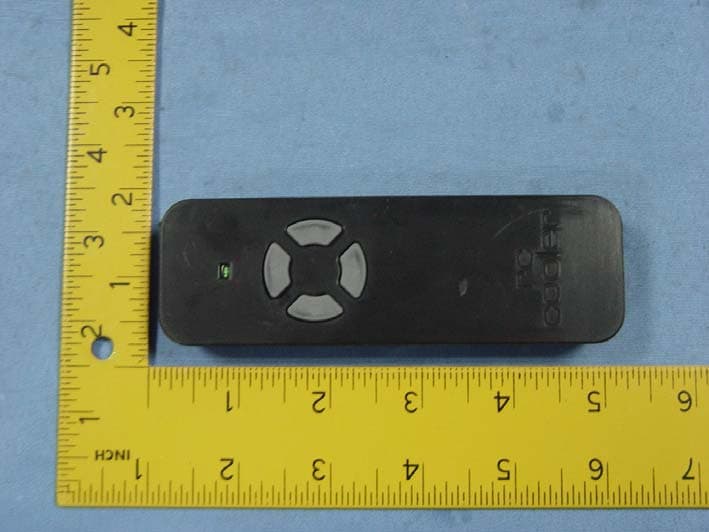
RSD-22029TX
Aug 11, 2014R/C Vehicle
Equipment Class
DXX - Part 15 Low Power Communication Device Transmitter
RSD-425XXTX
May 26, 20142.4G VECHICLE
Equipment Class
DXX - Part 15 Low Power Communication Device Transmitter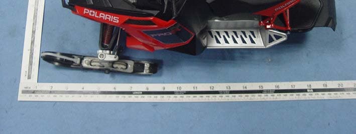
RSD-425XXRX
May 26, 20142.4G VECHICLE
Equipment Class
DXX - Part 15 Low Power Communication Device Transmitter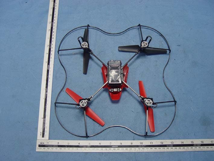
RSD-22033V2RX
May 15, 20142.4G Flier
Equipment Class
DXX - Part 15 Low Power Communication Device Transmitter
RSD-22033TX
May 30, 20132.4G Flier
Equipment Class
DXX - Part 15 Low Power Communication Device Transmitter