RSNCM1000Cellular Phone Booster
Cellphone-Mate Inc. dba SureCall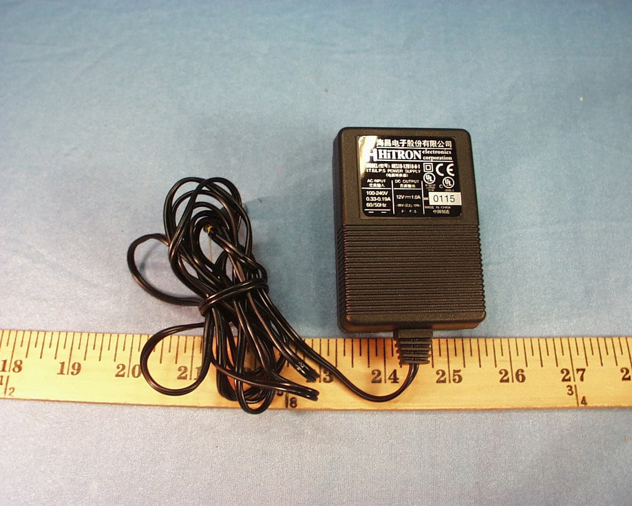
Click to zoom
Application Details
- Equipment Class
- PCB - PCS Licensed Transmitter
- Date of Grant
- Mar 07, 2004
- Application Purpose
- Original Equipment
- Date of Application
- Mar 07, 2004
- Equipment Note
- Cellular Phone Booster
- Frequency Range
- 1851.00000000 - 1909.00000000
- Country
- United States
Documents & Files
Document Text
Text extracted from the exhibit documents filed with the FCC. Open a document above to read the original.
Users Manual
User Instructions (1) Place the booster in a suitable location and plug the 12V DC adaptor power cord into the power jack or cigarette socket. (2) Plug in the antenna and make sure to tighten it. (3) Connect one end of the cell phone adaptor cable to the booster where it is marked "Phone" and the other end to the cell phone antenna port. (4) Make sure all the connections are tight and secure, turn on the power switch. A green light will indicate the booster is ready to use. (5) Press any cell phone key to refresh its communication with the base station. Seconds later you should notice that the strength of the signal gets improved. Now you are ready to make and receive phone calls. Note: It is normal for the booster box to be warm during operation. Safety Warning: human body should always be separated at least 25 cm away from the antenna of the booster. Warning: Changes or modifications not approved by CM technical specialist could void the warranty and cause health issues. Troubleshooting: During operation, if the booster interferes with your radio or other electronic reception, move the box away from the radio and other electronic equipments. Consult a Cellphone-Mate technical specialist by sending email to help@Cellphone- Mate.com www.Cellphone-Mate.com (510) 505-0469
Cover Letter(s)
.Cellpho,n«~-Mate Inc. 36543 San Pedro Dr. *:277 Fremont, CA 94535 Tele: (510) 366-5445 Fax: (610) 505-0469 Date: January 7, 2004 Federal Communications Commission Equipment Authorization branch 7435 Oakland Mills Road Columbia, MD 21046 Re: Request for Confidentiality Gentlemen: In reference to the application under FCC ID: RSN C M /ootJ and pursuant to Sections 0.457(d)(I)(ii) and 0.459 of the Commission's Rules, the Applicant hereby requests confidential treatment of the accompanying infolmation as outlined below: Schematics Block Diagrams Theory of Operation. These documents contain detailed system and equipment description and related information about the product that Cellphone-Mate Inc. considers to be proprietary, confidential, and a custom design and, otherwise, would not release to the general public. Since this design is a basis from which future technological products will evolve, Cell phone-Mate Inc. considers that this information would be of benefit to its competitors, and that disclosure of the information in these documents would give competitors an unfair advantage in the market. Sincerely, W D ' ~?-~-'-- HO~* CEO Cellphone-Mate Inc.
Cover Letter(s)
1 Mike Kuo From: Claire Hoque Sent: February262004Thursday 10:51 AM To: Mike Kuo Cc: Thu Chan; Kathy Yao; Frank Ibrahim Subject: RE: Cellphone-Mate Inc. , FCC ID:RSNCM1000, AN04T3638 Hi Mike, Here are the answers. Question #1: Please provide MPE information to address RF exposure compliance. <Claire> pls see the attached MPE. MPE Calculations for Cellphone... Question #2: In the antenna specification attachment, it provides 2 different antenna gain ( 3 or 5 dBi ). Please provide antenna specification for each of antenna which apply to the frequency range of this amplifier and the cable lost with 2000 mm in cable length. <Cellphone-Mate> two spec. are attached. Cable loss: The type of cable we used is RG-174, with loss of 31.7dB/100 feet, for 2000 mm, which is 6.56 feet, total cable loss will be: 2.08 dB. 5dBi antenna spec.pdf 3dBi antenna spec.pdf Question #3: In the EMC test report, the antenna gain are listed as 5 dBi and 3.5 dBi which do not agree with antenna specification. Please explain. <Cellphone-Mate> 3.5 dBi is a mistake,an over statement, please always use 3 dBi from now on for all FCC documents, and please make all the corresponding changes if you can. Thu has revised the test report. 03U2456 FCC 24 Report(revised)... Question #4: In the user manual, there is no instruction provided about the separation distance shall be maintained. Please provide revised user manual. <Cellphone-Mate>revised manual is attached. Based on our calculations, assuming a 2 watt power input to the antenna; a 5 dBi max antenna gain; and a power density limit of 12.34 w/m^2 at 1851 MHz, the distance limit to meet FCC MPE is 21.5 cm. To be conservative, I will put 25 cm in the user manual. . CM1000 User Manual-revised.pdf... Question #5: By comparing the RF conducted output power and the EIRP measured data, the EIRP output power for 5 dBi antenna gain are about 4 dBi lower than 3dBi EIRP. Please explain why the higher antenna gain with lower EIRP readings. <Frank> the 5 dBi antenna had lower power even though it has higher gain than the other antenna is the fact that there is a permanent cable connected to it that has a loss. Question #6: Please provide modification report signed the applicant to acknowledge the modification made during final 2 compliance tests will be incorporated in each unit sold in the U.S.. <Cellphone-Mate> signed report is attached. signed modification report.pdf... Question #7: Is this device capable of amplifying CDMA modulation and GSM modulation in one box or different modulation will require to have different RF board ? <Cellphone-Mate> Yes, both in one box, that’s why your lab did separate test for CDMA and GSM. Thanks, Claire
ID Label/Location Info
PROPOSED FCC ID LABEL AND LOCATION CELLPHONE-MATE INC. This device complies with Part 24 of the FCC Rules. FCC ID: RSNCM1000 FCC ID LABEL LOCATION
Parts List/Tune Up Info
February 3, 2004 ________________________________________________________________________________ To whom it might concern: .... Because of the simplification of our design, all the components used in it such as: resistors, capacitors, inductors or diplexer etc. has fixed value, and doesn’t need adjustment during volume product, and no tune up procedure is needed for the purpose of verify frequency or output power level etc. .... Sincerely yours, Hongtao Zhan CEO Cellphone-Mate Inc. Cellphone-Mate Inc. 36543 San Pedro Dr. #277 Fremont, CA 94536 Tele: (510) 505 0469
Parts List/Tune Up Info
Frequency Range (MHz) 1850-1910/1930-1990 Bandwidth (MHz) 60/60 VSWR =2.0 Gain (dBi) 3 Rated Power (W) 50 Input Impedance (?) 50 Polarization Type Vertical Length (mm) 98 +/- 1 Cable length (mm) NA Connector Type SMA
Parts List/Tune Up Info
Frequency Range (MHz) 1850-1910/1930-1990 Bandwidth (MHz) 60/60 VSWR =2.0 Gain (dBi) 5 Rated Power (W) 50 Input Impedance (?) 50 Polarization Type Vertical Length (mm) =280 Cable length (mm) 2000 Connector Type SMA
RF Exposure Info
CELLPHONE-MATE, INC. PROJECT #: 03U2456 CDMA: 5dBi Antenna Gain: Formula used in the MPE Calculations: E^2/3770 = S, mW/cm2 Pwatts*Ggain = 10^(PdBm-30+GdBi)/10) E, V/m = (Pwatts*Ggain*30)^.5/d, meters d = ((Pwatts*G*30)/3770*S))^0.5 --------- (A) Since S (mW/cm2) = 1.00 from 1.1310 Table 1 PG (dBm) = 24.8 EUT output power EIRP Substitute these parameters into the A above, we have MPE safe distance d (cm) = 4.9cm NOTE: For mobile or fixed location transmitters, minimum separation distance is 20 cm, even if calculations indicate MPE distance is less 3.5dBi Antenna Gain: Formula used in the MPE Calculations: E^2/3770 = S, mW/cm2 Pwatts*Ggain = 10^(PdBm-30+GdBi)/10) E, V/m = (Pwatts*Ggain*30)^.5/d, meters d = ((Pwatts*G*30)/3770*S))^0.5 --------- (A) Since S (mW/cm2) = 1.00 from 1.1310 Table 1 PG (dBm) = 29.3 EUT output power EIRP Substitute these parameters into the A above, we have MPE safe distance d (cm) = 8.2cm NOTE: For mobile or fixed location transmitters, minimum separation distance is 20 cm, even if calculations indicate MPE distance is less GSM: 5dBi Antenna Gain: Formula used in the MPE Calculations: E^2/3770 = S, mW/cm2 Pwatts*Ggain = 10^(PdBm-30+GdBi)/10) E, V/m = (Pwatts*Ggain*30)^.5/d, meters d = ((Pwatts*G*30)/3770*S))^0.5 --------- (A) Since S (mW/cm2) = 1.00 from 1.1310 Table 1 PG (dBm) = 23.7 EUT output power EIRP Substitute these parameters into the A above, we have MPE safe distance d (cm) = 4.3cm NOTE: For mobile or fixed location transmitters, minimum separation distance is 20 cm, even if calculations indicate MPE distance is less 3.5dBi Antenna Gain: Formula used in the MPE Calculations: E^2/3770 = S, mW/cm2 Pwatts*Ggain = 10^(PdBm-30+GdBi)/10) E, V/m = (Pwatts*Ggain*30)^.5/d, meters d = ((Pwatts*G*30)/3770*S))^0.5 --------- (A) Since S (mW/cm2) = 1.00 from 1.1310 Table 1 PG (dBm) = 26.3 EUT output power EIRP Substitute these parameters into the A above, we have MPE safe distance d (cm) = 5.8cm NOTE: For mobile or fixed location transmitters, minimum separation distance is 20 cm, even if calculations indicate MPE distance is less
Test Report
FCC CFR47 CERTIFICATION PART 24E TEST REPORT FOR CELLULAR PHONE AMPLIFIER MODEL: CM 1000 FCC ID:RSNCM1000 REPORT NUMBER: 03U2456-1 ISSUE DATE: JANUARY 14, 2004 Prepared for CELLPHONE-MATE, INC. 36543 SAN PEDRO DRIVE # 277 FREMONT, CA 94536 U.S.A. Prepared by COMPLIANCE CERTIFICATION SERVICES 561F MONTEREY ROAD, ROUTE 2 MORGAN HILL, CA 95037, USA TEL: (408) 463-0885 FAX: (408) 463-0888 REPORT NO: 03U2456-1 DATE: JANUARY 14, 2004 EUT: CELLULAR PHONE AMPLIFIER, MODEL: CM 1000 FCC ID: RSNCM1000 Page 2 of 61 COMPLIANCE CERTIFICATION SERVICES DOCUMENT NO: CCSUP4031A 561F MONTEREY ROAD, MORGAN HILL, CA 95037 USA TEL: (408) 463-0885 FAX: (408) 463-0888 This report shall not be reproduced except in full, without the written approval of CCS. This document may be altered or revised by Compliance Certification Services personnel only, and shall be noted in the revision section of the document. TABLE OF CONTENT 1. TEST RESULT CERTIFICATION .............................................................3 2. EUT DESCRIPTION .....................................................................................4 3. TEST METHODOLOGY..............................................................................4 4. TEST FACILITY ...........................................................................................4 5. ACCREDITATION AND LISTING ............................................................4 6. MEASURING INSTRUMENT CALIBRATION .......................................4 7. INSTRUMENTATION LIST AND EUT SETUP INFORMATION........5 8. MODIFICATIONS LIST ..............................................................................7 9. TEST SETUP, PROCEDURE AND RESULT............................................8 9.1. SECTION 2.1046: RF POWER OUTPUT (CONDUCTED) ....................................................... 8 9.4. SECTION 2.1046: RF POWER OUTPUT (RADIATED) ......................................................... 16 9.2. SECTION 2.1047: MODULATION CHARACTERISTICS ..................................................... 24 9.3. SECTION 2.1049: OCCUPIED BANDWIDTH ........................................................................ 24 9.4. SECTION 2.1051: SPURIOUS EMISSIONS AT ANTENNA TERMINAL ............................ 38 9.5. SECTION 2.1053: FIELD STRENGTH OF SPURIOUS RADIATION ................................... 49 9.6. SECTION 2.1055: FREQUENCY STABILITY ........................................................................ 56 9.7. POWERLINE CONDUCTED EMISSION ................................................................................ 56 10. APENDIX ......................................................................................................61 10.1. EXTERNAL & INTERNAL PHOTOS .................................................................................. 61 10.2. SCHEMATICS ....................................................................................................................... 61 10.3. BLOCK DIAGRAM ............................................................................................................... 61 10.4. USER MANUAL ....................................................................................................................61 REPORT NO: 03U2456-1 DATE: JANUARY 14, 2004 EUT: CELLULAR PHONE AMPLIFIER, MODEL: CM 1000 FCC ID: RSNCM1000 Page 3 of 61 COMPLIANCE CERTIFICATION SERVICES DOCUMENT NO: CCSUP4031A 561F MONTEREY ROAD, MORGAN HILL, CA 95037 USA TEL: (408) 463-0885 FAX: (408) 463-0888 This report shall not be reproduced except in full, without the written approval of CCS. This document may be altered or revised by Compliance Certification Services personnel only, and shall be noted in the revision section of the document. 1. TEST RESULT CERTIFICATION COMPANY NAME: CELLPHONE-MATE, INC. 36543 SAN PEDRO DRIVE # 277 FREMONT, CA 94536 U.S.A. EUT DESCRIPTION CELLULAR PHONE AMPLIFIER MODEL NAME: CM 1000 DATE TESTED: JANUARY 14, 2004 TYPE OF EQUIPMENT INTENTIONAL RADIATOR, CELL PHONE AMPLIFIER MEASUREMENT PROCEDURE ANSI 63.4 / 2001, TIA/EIA 603 PROCEDURE CERTIFICATION FCC RULE CFR 47 PART 24 SUBPART E Compliance Certification Services, Inc. tested the above equipment for compliance with the requirement set forth in CFR 47, PART 24 subpart E Cellular Radiotelephone Service. The equipment in the configuration described in this report, shows the measured emission levels emanating from the equipment do not exceed the specified limit. Note : This document reports conditions under which testing was conducted and results of tests performed. This document may not be altered or revised in any way unless done so by Compliance Certification Services and all revisions are duly noted in the revisions section. Any alteration of this document not carried out by Compliance Certification Services will constitute fraud and shall nullify the document. Tested By: Released For CCS By: FRANK IBRAHIM THU CHAN EMC SUPERVISOR EMC SUPERVISOR COMPLIANCE CERTIFICATION SERVICES COMPLIANCE CERTIFICATION SERVICES REPORT NO: 03U2456-1 DATE: JANUARY 14, 2004 EUT: CELLULAR PHONE AMPLIFIER, MODEL: CM 1000 FCC ID: RSNCM1000 Page 4 of 61 COMPLIANCE CERTIFICATION SERVICES DOCUMENT NO: CCSUP4031A 561F MONTEREY ROAD, MORGAN HILL, CA 95037 USA TEL: (408) 463-0885 FAX: (408) 463-0888 This report shall not be reproduced except in full, without the written approval of CCS. This document may be altered or revised by Compliance Certification Services personnel only, and shall be noted in the revision section of the document. 2. EUT DESCRIPTION 1900 MHz CDMA/GSM Cell Phone Amplifier: - an EIRP of 24.8 dBm for CDMA mode, with 5 dBi gain antenna. - an EIRP of 29.3 dBm for CDMA mode, with 3 dBi gain antenna. - an EIRP of 23.7 dBm for GSM mode, with 5 dBi gain antenna. - an EIRP of 26.3 dBm for GSM mode, with 3 dBi gain antenna. 3. TEST METHODOLOGY Both conducted and radiated testing were performed according to the procedures documented on chapter 13 of ANSI C63.4 and FCC CFR 47 2.1046, 2.10…
Text truncated - open the document above for the full version.
Test Setup Photos
REPORT NO: 03U2456-1 DATE: JANUARY 14, 2004 EUT: CELLULAR PHONE AMPLIFIER, MODEL: CM 1000 FCC ID: RSNCM1000 Page 9 of 61 COMPLIANCE CERTIFICATION SERVICES DOCUMENT NO: CCSUP4031A 561F MONTEREY ROAD, MORGAN HILL, CA 95037 USA TEL: (408) 463-0885 FAX: (408) 463-0888 This report shall not be reproduced except in full, without the written approval of CCS. This document may be altered or revised by Compliance Certification Services personnel only, and shall be noted in the revision section of the document. REPORT NO: 03U2456-1 DATE: JANUARY 14, 2004 EUT: CELLULAR PHONE AMPLIFIER, MODEL: CM 1000 FCC ID: RSNCM1000 Page 21 of 61 COMPLIANCE CERTIFICATION SERVICES DOCUMENT NO: CCSUP4031A 561F MONTEREY ROAD, MORGAN HILL, CA 95037 USA TEL: (408) 463-0885 FAX: (408) 463-0888 This report shall not be reproduced except in full, without the written approval of CCS. This document may be altered or revised by Compliance Certification Services personnel only, and shall be noted in the revision section of the document. Radiated Emissions Front, with 5 dBi Gain antenna: Back, with 5 dBi Gain antenna: REPORT NO: 03U2456-1 DATE: JANUARY 14, 2004 EUT: CELLULAR PHONE AMPLIFIER, MODEL: CM 1000 FCC ID: RSNCM1000 Page 22 of 61 COMPLIANCE CERTIFICATION SERVICES DOCUMENT NO: CCSUP4031A 561F MONTEREY ROAD, MORGAN HILL, CA 95037 USA TEL: (408) 463-0885 FAX: (408) 463-0888 This report shall not be reproduced except in full, without the written approval of CCS. This document may be altered or revised by Compliance Certification Services personnel only, and shall be noted in the revision section of the document. Front, with 3.5 dBi Gain antenna: Back, with 3.5 dBi Gain antenna: REPORT NO: 03U2456-1 DATE: JANUARY 14, 2004 EUT: CELLULAR PHONE AMPLIFIER, MODEL: CM 1000 FCC ID: RSNCM1000 Page 59 of 61 COMPLIANCE CERTIFICATION SERVICES DOCUMENT NO: CCSUP4031A 561F MONTEREY ROAD, MORGAN HILL, CA 95037 USA TEL: (408) 463-0885 FAX: (408) 463-0888 This report shall not be reproduced except in full, without the written approval of CCS. This document may be altered or revised by Compliance Certification Services personnel only, and shall be noted in the revision section of the document. LINE CONDUCTION - FRONT REPORT NO: 03U2456-1 DATE: JANUARY 14, 2004 EUT: CELLULAR PHONE AMPLIFIER, MODEL: CM 1000 FCC ID: RSNCM1000 Page 60 of 61 COMPLIANCE CERTIFICATION SERVICES DOCUMENT NO: CCSUP4031A 561F MONTEREY ROAD, MORGAN HILL, CA 95037 USA TEL: (408) 463-0885 FAX: (408) 463-0888 This report shall not be reproduced except in full, without the written approval of CCS. This document may be altered or revised by Compliance Certification Services personnel only, and shall be noted in the revision section of the document. LINE CONDUCTION - BACK
Contact Information
Applicant
Dennis Findley(Director of Operations)
Test Firm
Compliance Certification Services IncSteve Cheng
Technical Specifications
| # | Rule Parts | Frequency Range | Power Output | Emission | Tolerance |
|---|---|---|---|---|---|
| 2 | 24E | 1.85 GHz - 1.91 GHz | 161.00 mW | GXW | Amp |
Other Applications from Cellphone-Mate Inc. dba SureCall
RSN-FIBERMAXRU2
Sep 01, 2026SignalMax Fiber DAS V2 .0
Equipment Class
B2I - Part 20 Industrial Booster (CMRS)RSN-FULTRA5G
Aug 28, 2026Broadband Consumer Signal Booster
Equipment Class
B2W - Part 20 Wideband Consumer Booster (CMRS)RSN-FIBERMAXMU2
Aug 28, 2026SignalMax Fiber DAS V2 .0
Equipment Class
B2I - Part 20 Industrial Booster (CMRS)
RSNF4H-MAX
Jun 29, 2021Dual Enclosure Wideband Consumer booster Roof top unit
Equipment Class
B2W - Part 20 Wideband Consumer Booster (CMRS)
RSNF4H-MAXS
Jun 29, 2021Dual Enclosure Wideband Consumer booster Indoor unit
Equipment Class
B2W - Part 20 Wideband Consumer Booster (CMRS)