RSNCM2000RF Amplifier
Cellphone-Mate Inc. dba SureCall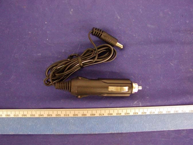
Click to zoom
Application Details
- Equipment Class
- AMP - Amplifier
- Date of Grant
- Dec 28, 2004
- Application Purpose
- Original Equipment
- Date of Application
- Dec 28, 2004
- Equipment Note
- RF Amplifier
- Frequency Range
- 1850.20000000 - 1909.80000000
- Country
- United States
Documents & Files
Document Text
Text extracted from the exhibit documents filed with the FCC. Open a document above to read the original.
Users Manual
User Instructions (1) Place the booster in a suitable location and plug the 12V DC adaptor power cord into the power jack or cigarette socket. (2) Plug in the antenna and make sure to tighten it. (3) Connect one end of the cell phone adaptor cable to the booster where it is marked "Phone" and the other end to the cell phone antenna port. (4) Make sure all the connections are tight and secure, turn on the power switch. A green light will indicate the booster is ready to use. (5) Press any cell phone key to refresh its communication with the base station. Seconds later you should notice that the strength of the signal gets improved. Now you are ready to make and receive phone calls. Note: It is normal for the booster box to be warm during operation. Safety Warning: human body should always be separated at least 25 cm away from the antenna of the booster. Warning: Changes or modifications not approved by CM technical specialist could void the warranty and cause health issues. Troubleshooting: During operation, if the booster interferes with your radio or other electronic reception, move the box away from the radio and other electronic equipments. Consult a Cellphone-Mate technical specialist by sending email to help@Cellphone- Mate.com www.Cellphone-Mate.com 1-888-365-MATE
External Photos
EXHIBIT C - EUT EXTERNAL PHOTOGRAPHS EUT – Chassis Top View EUT – Chassis Bottom View EUT – Port View AC/DC Adapter View DC Adapter View Antenna View 3dBi Antenna View 5dBi Antenna View
ID Label/Location Info
EXHIBIT A - FCC PRODUCT LABELING AND WARNING STATEMENT FCC ID Label Specifications: Text is black or white in color and is left justified. Labels are silk-screened and shall be “permanently affixed” at a conspicuous location on the EUT. Proposed Label Location on EUT FCC Warning Statement A FCC Warning Statement is provided in the product manual. FCC ID: RSNCM2000
Internal Photos
EXHIBIT C - EUT INTERNAL PHOTOGRAPHS EUT – Component View EUT – Solder View
Operational Description
Theory of Operation This amplifier is made up of 3 parts: power supply circuit, transmitting circuit and receiving circuit. It is used to amplify the signal to and from PCS or cellular band cellphone. Power supply circuit uses a 7805 to regulate the input DC12V voltage to DC 5V. It uses a diode to protect the circuit from input with reverse polarity. Also, a switch and a power- on indication lamp are used. The switch turns on and off the green lamp as well as the whole circuits board. Inserted as part of base station and cellphone power control loop, the transmitting circuit amplifies the RF signal from cellphone large enough to meet tower requirements. Cellphone adjusts its output adaptively according to the commands from base station. The signal from cellphone first goes into a diplexer (HITACHI SLF-190LB-K) which separate the frequency between 800MHz and 1900MHz, and then goes into another diplexer (TOKO TDPH-1880L-13 for 1900MHz, TDPF-836E-13 for 800MHz) which separate the signal from receiving path, then the filtered signal goes into a power amplifier with gain control (2174 for 1900MHz, 2173 for 800MHz). The amplifier will amplify the signal based on the input signal strength. After the amplifier, the signal will goes into the other diplexer and then goes to the antenna. The receiving circuits amplify the RF signal from antenna and improve cellphone’s sensitivity. The dual-band antenna has 3 or 5 dBi gain, it gathers the signal and send it to the diplexer (HITACHI SLF-190LB-K), which separates the frequency between 800MHz and 1900MHz and then goes into another diplexer(TOKO TDPH-1880L-13 for 1900MHz, TDPF-836E-13 for 800MHz ) which separates the receiving signal from transmit signal. The filtered signal then goes into 2-stage LNA. Each stage is mainly made up of a 54143, which is a LNA IC with high quality. The output signal will go into the second diplexer and then to a SMA socket, which connected to a cable that attached to cellphone. In summary, this device will amplify dual-band signal bi-directionally, thus improve cellphone reception and increase coverage area.
Parts List/Tune Up Info
Part TypeDesignatorFootprintQuantity 0.01uF C3 C7 C12 C17 C21 C24 C27 C49 C53 C58 C62 C65 C68 080513 0.1uF C4 C6 C13 C16 C20 C23 C26 C50 C52 C57 C61 C64 C67 080513 1.0uFC3008051 1kR708051 2.6VD1 D308052 2.7*2R608051 2.7R5 R6 R43 R4808054 2K R1 R3 R11 R13 R17 R19 R25 R27 R33 R35 R44 R46 080512 2pC30 C7108052 3pC29 C7008052 4.7KR10,R1508052 1pC1 C4708052 10uF C5 C8 C11 C18 C28 C51 C54 C59 C69 12109 24KR7 R22 R30 R38 08054 39R12 R18 R26 R34 08054 68R2 R4508052 102 C2 C14 C15 C19 C22 C25 C31 C32 C35 C36 C40 C41 C44 C45 C48 C56 C60 C63 C66 080519 180R15 R5008052 240R808051 510 R10 R24 R32 R40 R49 08055 2174IC1QFN1 2173IC2QFN1 54143U1,U2,U3,U4SO4 SMAJ1,J2SMA2 SWITCHK1SWITCH1 JACKJ3JACK1 LEDD3LED1 TDPH-1880L-13 DiplexrTOKO2 7805U3TO-2201 TDPF-836E-13 DiplexrTOKO2 SLF-190LB-KDiplexrHitachi2
Test Report
Note: The test report is specially limited to the above company and the product model only. It may not be duplicated without prior written consent of Bay Area Compliance Laboratory Corporation. This report must not be used by the client to claim product certification, approval, or endorsement by NVLAP, NIST or any agency of the US Government. FCC PART 24 TYPE APPROVAL EMI MEASUREMENT AND TEST REPORT For Cellphone-Mate, Inc. 36543 San Pedro Dr. Suite 277 Fremont, CA 94536 FCC ID: RSNCM2000 This Report Concerns: Original Report Equipment Type: RF Amplifier Test Engineer: Ming Jin / Report No.: R0408232 Report Date: 2004-09-08 Reviewed By: Ling Zhang / Prepared By: Bay Area Compliance Laboratory Corporation (BACL) 230 Commercial Street Sunnyvale, CA 94085 Tel: (408) 732-9162 Fax: (408) 732 9164 CELLPHONE-MATE, INC. FCC ID: RSNCM2000 Report # R0408232Rpt.doc Page 2 of 53 FCC Part 24 Type Approval Report TABLE OF CONTENTS GENERAL INFORMATION.......................................................................................................................................3 PRODUCT DESCRIPTION FOR EQUIPMENT UNDER TEST (EUT) ....................................................................................3 OBJECTIVE...................................................................................................................................................................3 RELATED SUBMITTAL(S)/GRANT(S).............................................................................................................................3 TEST METHODOLOGY..................................................................................................................................................3 TEST FACILITY.............................................................................................................................................................3 SYSTEM TEST CONFIGURATION ..........................................................................................................................4 JUSTIFICATION.............................................................................................................................................................4 BLOCK DIAGRAM.........................................................................................................................................................4 EQUIPMENT MODIFICATIONS.......................................................................................................................................4 EXTERNAL I/O CABLING LIST AND DETAILS...............................................................................................................4 POWER SUPPLY INFORMATION.....................................................................................................................................4 TEST SETUP BLOCK DIAGRAM.....................................................................................................................................5 SUMMARY OF TEST RESULTS ...............................................................................................................................6 §2.1047 - MODULATION CHARACTERISTIC .......................................................................................................7 §2.1053 - SPURIOUS RADIATED EMISSIONS .......................................................................................................8 APPLICABLE STANDARD..............................................................................................................................................8 TEST PROCEDURE........................................................................................................................................................8 TEST EQUIPMENT LIST AND DETAILS...........................................................................................................................8 ENVIRONMENTAL CONDITIONS....................................................................................................................................8 TEST RESULT...............................................................................................................................................................9 §2.1046, & §24.232 –CONDCUTED POWER OUTPUT.........................................................................................13 APPLICABLE STANDARD............................................................................................................................................13 TEST PROCEDURE......................................................................................................................................................13 TEST EQUIPMENT LIST AND DETAILS.........................................................................................................................13 ENVIRONMENTAL CONDITIONS..................................................................................................................................13 TEST RESULTS...........................................................................................................................................................14 §2.1049, & §24.238(B) - EMISSION BANDWIDTH ...............................................................................................15 APPLICABLE STANDARDS..........................................................................................................................................15 TEST PROCEDURE......................................................................................................................................................15 TEST EQUIPMENT.......................................................................................................................................................15 ENVIRONMENTAL CONDITIONS..................................................................................................................................15…
Text truncated - open the document above for the full version.
Test Report
CELLPHONE-MATE, INC. FCC ID: RSNCM2000 Report # R0408232Rpt.doc Page 30 of 53 FCC Part 24 Type Approval Report CELLPHONE-MATE, INC. FCC ID: RSNCM2000 Report # R0408232Rpt.doc Page 31 of 53 FCC Part 24 Type Approval Report CELLPHONE-MATE, INC. FCC ID: RSNCM2000 Report # R0408232Rpt.doc Page 32 of 53 FCC Part 24 Type Approval Report CELLPHONE-MATE, INC. FCC ID: RSNCM2000 Report # R0408232Rpt.doc Page 33 of 53 FCC Part 24 Type Approval Report CELLPHONE-MATE, INC. FCC ID: RSNCM2000 Report # R0408232Rpt.doc Page 34 of 53 FCC Part 24 Type Approval Report CELLPHONE-MATE, INC. FCC ID: RSNCM2000 Report # R0408232Rpt.doc Page 35 of 53 FCC Part 24 Type Approval Report CELLPHONE-MATE, INC. FCC ID: RSNCM2000 Report # R0408232Rpt.doc Page 36 of 53 FCC Part 24 Type Approval Report CELLPHONE-MATE, INC. FCC ID: RSNCM2000 Report # R0408232Rpt.doc Page 37 of 53 FCC Part 24 Type Approval Report CELLPHONE-MATE, INC. FCC ID: RSNCM2000 Report # R0408232Rpt.doc Page 38 of 53 FCC Part 24 Type Approval Report CELLPHONE-MATE, INC. FCC ID: RSNCM2000 Report # R0408232Rpt.doc Page 39 of 53 FCC Part 24 Type Approval Report CELLPHONE-MATE, INC. FCC ID: RSNCM2000 Report # R0408232Rpt.doc Page 40 of 53 FCC Part 24 Type Approval Report
Test Report
CELLPHONE-MATE, INC. FCC ID: RSNCM2000 Report # R0408232Rpt.doc Page 41 of 53 FCC Part 24 Type Approval Report §2.1051, & §24.238(a) - SPURIOUS EMISSIONS AT ANTENNA TERMINALS Applicable Standard Requirements: CFR 47, § 2.1051 & §24.238(a). The spectrum was to be investigated to the tenth harmonics of the highest fundamental frequency as specified in § 2.1057. Test Procedure The EUT output was connected to the input of the Spectrum Analyzer through a calibrated attenuator. The resolution bandwidth of the Spectrum Analyzer was set to 30kHz, and th3e resulting data was plotted to show any out-of-band emissions up to the 10 th harmonic. Test Equipment List and Details Manufacturer Description Model Serial Number Cal. Date HP Spectrum Analyzer HP8564E 3943A01781 2003-08-01 HP Plotter HP7470A 2541A49659 Not Required Weinschel Attenuator MS015 58633 N/A * Statement of Traceability: BACL Corp. certifies that all calibrations have been performed in accordance to NVLAP requirements, traceable to the NIST. Environmental Conditions Temperature: 28° C Relative Humidity: 37% ATM Pressure: 1032 mbar The testing was performed by Ming Jin on 2004-08-25. Test Results Please refer to the hereinafter plots. CELLPHONE-MATE, INC. FCC ID: RSNCM2000 Report # R0408232Rpt.doc Page 42 of 53 FCC Part 24 Type Approval Report CELLPHONE-MATE, INC. FCC ID: RSNCM2000 Report # R0408232Rpt.doc Page 43 of 53 FCC Part 24 Type Approval Report CELLPHONE-MATE, INC. FCC ID: RSNCM2000 Report # R0408232Rpt.doc Page 44 of 53 FCC Part 24 Type Approval Report CELLPHONE-MATE, INC. FCC ID: RSNCM2000 Report # R0408232Rpt.doc Page 45 of 53 FCC Part 24 Type Approval Report CELLPHONE-MATE, INC. FCC ID: RSNCM2000 Report # R0408232Rpt.doc Page 46 of 53 FCC Part 24 Type Approval Report CELLPHONE-MATE, INC. FCC ID: RSNCM2000 Report # R0408232Rpt.doc Page 47 of 53 FCC Part 24 Type Approval Report CELLPHONE-MATE, INC. FCC ID: RSNCM2000 Report # R0408232Rpt.doc Page 48 of 53 FCC Part 24 Type Approval Report §2.1055 (a), §2.1055 (d), & §24.235 - FREQUENCY STABILITY This EUT is an amplifier, not a transmitter. There is no oscillator circuit in the EUT, therefore there is no frequency stability measurement required. CELLPHONE-MATE, INC. FCC ID: RSNCM2000 Report # R0408232Rpt.doc Page 49 of 53 FCC Part 24 Type Approval Report §24.238 – BAND EDGE Applicable Standard According to §24.238, the power of any emission outside of the authorized operating frequency ranges must be attenuated below the transmitting power (P) by a factor of at least 43 + 10 log(P) dB. Test Procedure The EUT output was connected to the input of the Spectrum Analyzer through a calibrated attenuator. The resolution bandwidth of the Spectrum Analyzer was set to 30kHz, and the center frequency was set to the band edge frequency. Test Equipment List and Details Manufacturer Description Model Serial Number Cal. Date HP Spectrum Analyzer HP8564E 3943A01781 2003-08-01 HP Plotter HP7470A 2541A49659 Not Required Weinschel Attenuator MS015 58633 N/A * Statement of Traceability: BACL Corp. certifies that all calibrations have been performed in accordance to NVLAP requirements, traceable to the NIST. Environmental Conditions Temperature: 28° C Relative Humidity: 37% ATM Pressure: 1032 mbar The testing was performed by Ming Jin on 2004-08-25. Test Results Please refer to the following plots. CELLPHONE-MATE, INC. FCC ID: RSNCM2000 Report # R0408232Rpt.doc Page 50 of 53 FCC Part 24 Type Approval Report CELLPHONE-MATE, INC. FCC ID: RSNCM2000 Report # R0408232Rpt.doc Page 51 of 53 FCC Part 24 Type Approval Report CELLPHONE-MATE, INC. FCC ID: RSNCM2000 Report # R0408232Rpt.doc Page 52 of 53 FCC Part 24 Type Approval Report CELLPHONE-MATE, INC. FCC ID: RSNCM2000 Report # R0408232Rpt.doc Page 53 of 53 FCC Part 24 Type Approval Report
Contact Information
Applicant
Dennis Findley(Director of Operations)
Test Firm
Bay Area Compliance LaboratoryJohn Chan
Technical Specifications
| # | Rule Parts | Frequency Range | Power Output | Emission |
|---|---|---|---|---|
| 6 | 24E | 1.85 GHz - 1.91 GHz | 447.00 mW | F9W |
Other Applications from Cellphone-Mate Inc. dba SureCall
RSN-FIBERMAXRU2
Sep 01, 2026SignalMax Fiber DAS V2 .0
Equipment Class
B2I - Part 20 Industrial Booster (CMRS)RSN-FULTRA5G
Aug 28, 2026Broadband Consumer Signal Booster
Equipment Class
B2W - Part 20 Wideband Consumer Booster (CMRS)RSN-FIBERMAXMU2
Aug 28, 2026SignalMax Fiber DAS V2 .0
Equipment Class
B2I - Part 20 Industrial Booster (CMRS)
RSNF4H-MAX
Jun 29, 2021Dual Enclosure Wideband Consumer booster Roof top unit
Equipment Class
B2W - Part 20 Wideband Consumer Booster (CMRS)
RSNF4H-MAXS
Jun 29, 2021Dual Enclosure Wideband Consumer booster Indoor unit
Equipment Class
B2W - Part 20 Wideband Consumer Booster (CMRS)