RSNCM2500WWiMax Single Direction Amplifier
Cellphone-Mate Inc. dba SureCall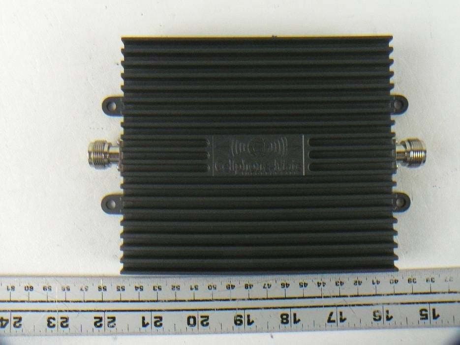
Click to zoom
Application Details
- Equipment Class
- TNB - Licensed Non-Broadcast Station Transmitter
- Date of Grant
- Dec 15, 2011
- Application Purpose
- Original Equipment
- Date of Application
- Dec 15, 2011
- Equipment Note
- WiMax Single Direction Amplifier
- Frequency Range
- 2496.00000000 - 2690.00000000
- Country
- United States
Documents & Files
Document Text
Text extracted from the exhibit documents filed with the FCC. Open a document above to read the original.
Users Manual
InstallaƟon Manual CM2500W Amplifier Copyright 2011 Cellphone-Mate, Inc. All rights reserved. i CHAPTER 1: Introduction - - - - - - - - - - - - - - - 1 1.1 - Package Contents - - - - - - - - - - - - - - - - 1 1.2 - Features & Benefits - - - - - - - - - - - - - - - 2 1.3 - Additional Items Needed - - - - - - - - - - - 2 1.4 - How It Works - - - - - - - - - - - - - - - - - - - 3 1.5 - About This Manual - - - - - - - - - - - - - - - 3 CHAPTER 2: Safety - - - - - - - - - - - - - - - - - - - - 5 2.1 - Safety Warnings 5 - - - - - - - - - - - - - - - - - CHAPTER 3: Planning - - - - - - - - - - - - - - - - - - 7 3.1 - Overview - - - - - - - - - - - - - - - - - - - - - - 7 3.2 - Exterior Antenna - - - - - - - - - - - - - - - - - 8 3.3 - Interior Antennas - - - - - - - - - - - - - - - - 9 3.4 - Antenna Separation - - - - - - - - - - - - - 10 3.5 - Calculating Signal Strength - - - - - - - - 13 3.6 - Amplifier Location - - - - - - - - - - - - - - - 14 3.7 - Accessories - - - - - - - - - - - - - - - - - - - - 15 3.8 - Need Help? - - - - - - - - - - - - - - - - - - - - 16 CHAPTER 4: Installation - - - - - - - - - - - - - - - - 17 4.1 - Selecting the Locations - - - - - - - - - - - 17 4.2 - Soft Installation - - - - - - - - - - - - - - - - - 17 4.3 - Exterior Antenna - - - - - - - - - - - - - - - - 17 4.4 - Internal Antennas - - - - - - - - - - - - - - - 18 4.5 - Mounting the Amplifier - - - - - - - - - - - 19 CHAPTER 5: Configuration & Testing - - - - - - 21 5.1 - DIP Switches and Lights - - - - - - - - - - - 21 5.2 - Initial Configuration - - - - - - - - - - - - - - 23 5.3 - Powering on the Amplifier - - - - - - - - - 23 5.4 - Testing - - - - - - - - - - - - - - - - - - - - - - - 24 5.5 - Adjusting the Amplifier - - - - - - - - - - - 24 5.6 - Automatic Shutdown - - - - - - - - - - - - - 26 CHAPTER 6: Warranty - - - - - - - - - - - - - - - - - 27 6.1 - Warranty Periods - - - - - - - - - - - - - - - - 27 6.2 - Warranty Information - - - - - - - - - - - - 28 6.3 - Contact Information - - - - - - - - - - - - - 30 CHAPTER 7: Regulatory Information - - - - - - 31 7.1 - FCC Information - - - - - - - - - - - - - - - - 31 Table of Contents CM2500W Amplifier - Installation Manual ii Copyright 2011 Cellphone-Mate, Inc. All rights reserved. Copyright & Trademark Information THIS MANUAL CONTAINS SAFETY, INSTALLATION, CONFIGURATION AND WARRANTY INFORMATION FOR YOUR CELLPHONE-MATE, INC (CMI) AMPLIFIER. CMI RECOMMENDS THAT YOU SAVE THIS MAN- UAL IN A READILY ACCESSIBLE LOCATION IN CASE ANY QUESTIONS ARISE ABOUT THIS PRODUCT. Copyright © 2011 by Cellphone-Mate, Inc. All rights reserved. SureCall is a registered trademark and Cellphone-Mate is a trademark of Cellphone-Mate, Inc. All other trademarks or registered trademarks are the property of their respective owners. Copyright 2011 Cellphone-Mate, Inc. All rights reserved. 1 This chapter introduces the CM2500W Amplifier and this manual. Read this entire manual before pro- ceeding with the installation. This manual is for all CM2500W models. 1.1 - Package Contents Your amplifier box contains the following items: •CM2500W amplifier. •Mounting kit (not shown). •DC power supply (not shown). •Wall anchors (not shown). CHAPTER 1: Introduction CM2500W Amplifier - Installation Manual 2 Copyright 2011 Cellphone-Mate, Inc. All rights reserved. 1.2 - Features & Benefits The CM2500W amplifier offers the following fea- tures and benefits: •Powerful in-building amplifier with 31dB of adjustable gain level. •Extends cellular signals in areas with poor cov- erage due to geographical location and/or building design. •Suitable for large areas up to about 30,000 square feet depending on outside signal strength and carrier frequency. •Sophisticated power control maintains maxi- mum output power at 2 watts EIRP. •Automatic oscillation detection and protec- tion system powers down the amplifier to pre- vent harmful radio interference (if equipped). 1.3 - Additional Items Needed The CM2500W amplifier requires the following additional components for a complete installation: •4G WiMAX compatible antenna (such as the CM288-W omni or CM230-W Yagi by Cell- phone-Mate, Inc.) •Lightning protector (CMLP). •Cable splitter if install- ing multiple antennas (up to six in a typical installation). CHAPTER 1: Introduction Copyright 2011 Cellphone-Mate, Inc. All rights reserved. 3 •Sufficient CM400 ultra low loss interior/exte- rior cable (for amplifi- ers above 55dB). •Sufficient CM240 ultra low loss interior/exte- rior cable (for amplifi- ers 55dB and below). •Up to 6 internal anten- nas (such as the CM222-W omnidirec- tional domes and/or CM248-W directional flat panel by Cell- phone-Mate, Inc.). •Grounded surge sup- pressor for DC power supply. 1.4 - How It Works The CM2500W amplifier boosts cellular signals from the nearest cellular tower to phones in a building and from those phones back to the tower to compensate for weak reception caused by dis- tance, topography, building structure, and/or other reasons. The amplifier receives the signal from an outside antenna, amplifies that signal, and then rebroadcasts it via the interior antenna(s) where it is picked up by cellular phones, modems, and data cards. The interior antennas also pick up signals from cellular devices and pass them to the amplifier. The amplifier boosts these signals and passes them to the exte- rior antenna for rebroadcast back to the tower. 1.5 - About This Manual This manual contains the following information: CM2500W Amplifier - Installation Manual 4 Copyright 2011 Cellphone-Mate, Inc. All rights reserved. •Introduction: This chapter introduces the CM2500W amplifier and this manual. •Safety: This chapter contains important safety information. •Planning: This chapter describes how to plan your installation for best results. •Installation: This chapter describes how to install the amplification system. •Warranty: This chapter contains warranty information for your amplification system. •Regulatory Information: This chapter contai…
Text truncated - open the document above for the full version.
Cover Letter(s)
FCC Confidential Authorization November 15th, 2011 FEDERAL COMMUNICATIONS COMMISSIONS Authorization and Evaluation Division 7435 Oakland Mills Road Columbia, MD 21046 Subject: Confidentiality Request regarding application for certification of FCC ID: RSNCM2500W In accordance with Sections 0.457 and 0.459 of the Commission’s Rules, Cellphone- Mate Inc. hereby requests long-term confidential treatment of information accompanying this application as outlined below: · Block Diagram · Schematics · Operation Description The above materials contain proprietary and confidential information not customarily released to the public. The public disclosure of these materials provides unjustified benefits to its competitors in the market. Sincerely, Hongtao Zhan CEO Cellphone-Mate Inc. 48820 Kato Rd. Suite 300B, Fremont, CA 94538 Cellphone-Mate Inc. 48820 Kato Rd. Suite 300B, Fremont, CA 94538 Tel: 1 888 365 MATE (6283) Fax: 510 996 7250 http://www.cellphone-mate.com
External Photos
Cellphone-Mate, Inc. FCC ID: RSNCM2500W Report Number: R1111152-27 Page 47 of 51 FCC Part 27 Test Report 15 EXHIBIT C - EUT PHOTOGRAPHS 15.1 EUT - Top View 15.2 EUT - Bottom View Cellphone-Mate, Inc. FCC ID: RSNCM2500W Report Number: R1111152-27 Page 48 of 51 FCC Part 27 Test Report 15.3 EUT - Side View 1 15.4 EUT - Side View 2 Cellphone-Mate, Inc. FCC ID: RSNCM2500W Report Number: R1111152-27 Page 49 of 51 FCC Part 27 Test Report 15.5 EUT – Uplink Port View 15.6 EUT – Downlink Port View
ID Label/Location Info
Cellphone-Mate, Inc. FCC ID: RSNCM2500W Report Number: R1111152-27 Page 43 of 51 FCC Part 27 Test Report 13 EXHIBIT A - FCC ID LABEL REQUIREMENTS 13.1 FCC ID Label Requirements FCC §2.925 Identification of equipment (a) Each equipment covered in an application for equipment authorization shall bear a nameplate or label listing the following: (1) FCC Identifier consisting of the two elements in the exact order specified in §2.926. The FCC Identifier shall be preceded by the term FCC ID in capital letters on a single line, and shall be of a type size large enough to be legible without the aid of magnification. Example: FCC ID: XXX123 Where: XXX—Grantee Code, 123—Equipment Product Code 13.2 FCC ID Label Contents Cellphone-Mate, Inc. FCC ID: RSNCM2500W Report Number: R1111152-27 Page 44 of 51 FCC Part 27 Test Report 13.3 FCC Label Location on EUT Label here
Internal Photos
Cellphone-Mate, Inc. FCC ID: RSNCM2500W Report Number: R1111152-27 Page 50 of 51 FCC Part 27 Test Report 15.7 EUT – Cover off View 15.8 EUT – Main PCB Board Front View Cellphone-Mate, Inc. FCC ID: RSNCM2500W Report Number: R1111152-27 Page 51 of 51 FCC Part 27 Test Report 15.9 EUT – Main PCB Board Rear View 15.10 AC/DC Power Supply View --- END OF REPORT ---
RF Exposure Info
Cellphone-Mate, Inc. FCC ID: RSNCM2500W Report Number: R1111152-27 Page 39 of 51 FCC Part 27 Test Report 11 FCC §1.1307(b), §27.52 & §2.1091 - RF EXPOSURE INFORMATION 11.1 Applicable Standard According to FCC §1.1310 and §2.1091 (Mobile Devices) RF exposure is calculated. Limits for General Population/Uncontrolled Exposure Frequency Range (MHz) Electric Field Strength (V/m) Magnetic Field Strength (A/m) Power Density (mW/cm 2 ) Averaging Time (minute) Limits for General Population/Uncontrolled Exposure 0.3-1.34 614 1.63 1 (100) 30 1.34-30 824/f 2.19/f 1 (180/f 2 ) 30 30-300 27.5 0.073 0.2 30 300-1500 / / f/1500 30 1500-100,000 / / 1.0 30 Note: f = frequency in MHz 1 = Plane-wave equivalent power density 11.2 MPE Prediction Predication of MPE limit at a given distance, Equation from OET Bulletin 65, Edition 97-01 S = PG/4πR² Where: S = power density P = power input to antenna G = power gain of the antenna in the direction of interest relative to an isotropic radiator R = distance to the center of radiation of the antenna Maximum peak output power at antenna input terminal (dBm): 8.57 M aximum peak output power at antenna input terminal (mW): 7. 19 Pre diction distance (cm): 60 Prediction frequency (MHz): 250 1 Ant enna Gain, typical (dBi): 14 Maximum Antenna Gain (numeric): 25.11 Power density at predication frequency and distance (mW/cm 2 ): 0.004 MPE limit for uncontrolled exposure at predication frequency (mW/cm 2 ): 1.0 (Note: The MPE was calculated assuming the cable loss between EUT and the antenna was 0 dB.) 11.3 Test Result For downlink, the indoor antenna with 14 dBi gain should have at least 60 cm prediction distance to meet the MPE limit. The distance needs to be addressed in the user manual.
Test Setup Photos
Cellphone-Mate, Inc. FCC ID: RSNCM2500W Report Number: R1111152-27 Page 45 of 51 FCC Part 27 Test Report 14 EXHIBIT B - TEST SETUP PHOTOGRAPHS 14.1 Radiated Emissions - Front View 14.2 Radiated Emissions 30 MHz to 1 GHz- Rear View Cellphone-Mate, Inc. FCC ID: RSNCM2500W Report Number: R1111152-27 Page 46 of 51 FCC Part 27 Test Report 14.3 Radiated Emissions above 1 GHz- Rear View
Contact Information
Applicant
Dennis Findley(Director of Operations)
Test Firm
Bay Area Compliance LaboratoryJohn Chan
Technical Specifications
| # | Rule Parts | Frequency Range | Power Output | Emission | Tolerance |
|---|---|---|---|---|---|
| 1 | 27 | 2.50 GHz - 2.69 GHz | 7.20 mW | G7W | Amp |
Other Applications from Cellphone-Mate Inc. dba SureCall
RSN-FIBERMAXRU2
Sep 01, 2026SignalMax Fiber DAS V2 .0
Equipment Class
B2I - Part 20 Industrial Booster (CMRS)RSN-FULTRA5G
Aug 28, 2026Broadband Consumer Signal Booster
Equipment Class
B2W - Part 20 Wideband Consumer Booster (CMRS)RSN-FIBERMAXMU2
Aug 28, 2026SignalMax Fiber DAS V2 .0
Equipment Class
B2I - Part 20 Industrial Booster (CMRS)
RSNF4H-MAX
Jun 29, 2021Dual Enclosure Wideband Consumer booster Roof top unit
Equipment Class
B2W - Part 20 Wideband Consumer Booster (CMRS)
RSNF4H-MAXS
Jun 29, 2021Dual Enclosure Wideband Consumer booster Indoor unit
Equipment Class
B2W - Part 20 Wideband Consumer Booster (CMRS)