RSNCM700VLTE Band In-Building Amplifier
Cellphone-Mate Inc. dba SureCall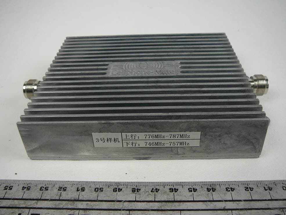
Click to zoom
Application Details
- Equipment Class
- TNB - Licensed Non-Broadcast Station Transmitter
- Date of Grant
- Jun 26, 2011
- Application Purpose
- Original Equipment
- Date of Application
- Jun 26, 2011
- Equipment Note
- LTE Band In-Building Amplifier
- Frequency Range
- 776.00000000 - 787.00000000
- Country
- United States
Documents & Files
Document Text
Text extracted from the exhibit documents filed with the FCC. Open a document above to read the original.
Users Manual
Cellphone-Mate Inc. SureCall CM700V Manual SureCall ® CM700V 4G LTE Amplifier User Manual FCC ID: RSNCM700V 2 Cellphone-Mate Inc. SureCall CM700V Manual CONTENTS OF THE PACKAGE fdgbsddg 1. CM700V Amplifier with connectors: N female type 2. Mounting Kit 3. 110V AC Power Adaptor 4. User Manual (this document) The following items need to be purchased separately before installation: 1. Dome antenna or other type of indoor antenna. 2. Yagi antenna or omni directional antenna for outdoor use. 3. CM400 cable that connects indoor antenna with the amplifier, length depends on actual situation. 4. CM400 cable that connects outdoor antenna with the amplifier. For further help, please consult the Cellphone-Mate website (www.Cellphone-Mate.com ) or call toll free at 888-365-MATE. SAFETY NOTES fdgbsddg The human body should always be separated from the indoor antenna of the Amplifier by at least 10 inches (25cm), and 24 inch(60cm) from the outdoor antenna, which could have a gain as high as 25.11(in numeric, equal to 14 dBi). Don't expose this product to extreme high or low temperatures. For example, putting the Amplifier under direct sunlight for too long may cause it to overheat and damage the electronic components inside. There are no consumer serviceable or modifiable parts inside this Amplifier product. Alteration or abuse of the Amplifier or other components will void this product’s warranty, and could be dangerous to the user. INSTALLATION INSTRUCTIONSgbsddg Warning: Never power on the units before completion of the installation. The signal is received by the outside antenna from the cell tower, then AMPLIFIED and transmitted to your phone through the inside antenna. When the phone transmits, the signal is received by the inside antenna, then AMPLIFIED and transmitted to the cell tower through the outside antenna. You can always refer to the picture on the next page which is there to help you through each step of the installation. STEP 1. Check to make sure the Power Switch on the amplifier is turned off. STEP 2. Install the CM700V amplifier on the wall with the mounting kits supplied. STEP 3. Connect the Inside Antenna to the side that shows “Indoor Ant.” using CM400 cable. STEP 4. Connect the Outside Antenna: Select an outside mounting location. For best performance, try to keep the antenna on top of the roof. The outside antenna should be located in an area with at least a 12” radius clear of obstructions, and other radiating elements. Use CM400 cable to connect to the amplifier. NOTE: Keep the separation distance between the inside and outside antennas to at least 100 ft apart to avoid RF oscillation. If not, then the amplification gain must be reduced with gain control switches on both sides of the unit for uplink and downlink. 3 Cellphone-Mate Inc. CM700V Manual STEP 5. Connect the Power Cord. STEP 6. Turn the Power Switch on Warning: To prevent damage to the Amplifier, before you plug in the Amplifier to an AC power outlet, please make sure that both sides are already connected with the cables from both the outdoor and indoor antennas. WARNING: after the power is turned ON, and before making any cellular phone calls, if the warning light is ON, oscillation is happening. POWER OFF immediately, then reduce both the uplink gain and downlink gain via the gain control switches on the side panel, or further increase separation distance between the two antennas, or do both until the power warning light is not ON when you are not making cellular phone calls. Note: 1. Power lights will always be on after you power up. STEP 7. After solving all oscillation problems, users can make cell phone calls to test how the repeater system works, adjusting the gain using attenuator as needed. Safety Warning: 1. Never plug in the power supply to the amplifier without attaching the outdoor antenna and indoor antenna to the amplifier. 2. Ensure that the distance between inside and outside antennas is a minimum of 100 feet from the amplifier. 3. If the Warning Light is on when you are not making cellular phone calls, DO NOT use the amplifier, turn it off immediately, since it may cause damage to the amplifier. TROUBLESHOOTING GUIDE During operation, if the Amplifier interferes with your radio or other electronic receivers, move the Amplifier further away from those devices. For a list of Frequently Asked Questions and a complete and up-to-date Troubleshooting Guide, please visit our website at: www.Cellphone-Mate.com You can also consult a Cellphone-Mate technical specialist directly by sending e-mail to us at: [email protected] Or write to: Cellphone-Mate, Inc. 48820 Kato Rd. Suite 300B Fremont, CA, 94538 U.S.A. Power Switch Power Switch N Connector for Indoor Power Light N Connector for Warning Light 4 Cellphone-Mate Inc. SureCall CM700V Manual WARRANTY 1. Cellphone-Mate, Inc. warrants to the Buyer that each of its products when shipped will be free from defects in material and workmanship and will perform in full accordance with applicable specifications. The limit of liability under this warranty is, at Cellphone-Mate, Inc.’s option, to repair or replace any product or part thereof which shall within TWO YEARS of purchase as determined by examination by Cellphone-Mate, Inc., proves to be defective in material and/or workmanship. Cellphone-Mate Inc must first authorize warranty returns in writing. Disassembly of any Cellphone-Mate, Inc. product by anyone other than an authorized representative of Cellphone-Mate, Inc. voids this warranty in its entirety. Cellphone-Mate, Inc. reserves the right to make changes in any of its products without incurring any obligation to make the same changes on previously delivered products. 2. As a condition to the warranties provided for herein, the Buyer will prepay the shipping charges for all products returned to Cellphone-Mate, Inc. for repair and Cellphone-Mate, Inc. will pay the return shipping with the exception of products returned from outside the United States i…
Text truncated - open the document above for the full version.
Cover Letter(s)
FCC Confidential Authorization June 2nd, 2011 FEDERAL COMMUNICATIONS COMMISSIONS Authorization and Evaluation Division 7435 Oakland Mills Road Columbia, MD 21046 Subject: Confidentiality Request regarding application for certification of FCC ID: RSNCM700V In accordance with Sections 0.457 and 0.459 of the Commission’s Rules, Cellphone- Mate Inc. hereby requests long-term confidential treatment of information accompanying this application as outlined below: · Block Diagram · Schematics · Operation Description · Parts List The above materials contain proprietary and confidential information not customarily released to the public. The public disclosure of these materials provides unjustified benefits to its competitors in the market. Sincerely, Hongtao Zhan CEO Cellphone-Mate Inc. 48820 Kato Rd. Suite 300B, Fremont, CA 94538 Cellphone-Mate Inc. 48820 Kato Rd. Suite 300B, Fremont, CA 94538 Tel: 1 888 365 MATE (6283) Fax: 510 996 7250 http://www.cellphone-mate.com
External Photos
Cellphone-Mate, Inc. FCC ID: RSNCM700V Report Number: R1105172-27 Page 83 of 88 FCC Part 27 Test Report 14 EXHIBIT C - EUT PHOTOGRAPHS 14.1 EUT - Top View 14.2 EUT - Bottom View Cellphone-Mate, Inc. FCC ID: RSNCM700V Report Number: R1105172-27 Page 84 of 88 FCC Part 27 Test Report 14.3 EUT - Side View 1 14.4 EUT - Side View 2 Cellphone-Mate, Inc. FCC ID: RSNCM700V Report Number: R1105172-27 Page 85 of 88 FCC Part 27 Test Report 14.5 EUT – Uplink Port View 14.6 EUT – Downlink Port View
ID Label/Location Info
SureCall TM LTE Band In-Building Amplifier Model#: CM700V Frequency Band: Uplink 776-787 MHz Downlink 746-757 MHz Gain: 70 dB Maximum Output Power: 2W EIRP FCC ID: RSNCM700V www.Cellphone-Mate.com 1-888-365-MATE (6283) Made In China
Internal Photos
Cellphone-Mate, Inc. FCC ID: RSNCM700V Report Number: R1105172-27 Page 86 of 88 FCC Part 27 Test Report 14.7 EUT – Cover off View 14.8 EUT – Cover off close up View Cellphone-Mate, Inc. FCC ID: RSNCM700V Report Number: R1105172-27 Page 87 of 88 FCC Part 27 Test Report 14.9 EUT – Main PCB Board Front View 14.10 EUT – Main PCB Board Rear View Cellphone-Mate, Inc. FCC ID: RSNCM700V Report Number: R1105172-27 Page 88 of 88 FCC Part 27 Test Report 14.11 AC/DC Power Supply View ***** END OF REPORT *****
RF Exposure Info
Cellphone-Mate, Inc. FCC ID: RSNCM700V Report Number: R1105172-27 Page 78 of 88 FCC Part 27 Test Report 11 FCC §1.1307(b), §27.52 & §2.1091 - RF EXPOSURE INFORMATION 11.1 Applicable Standard According to FCC §1.1310 and §2.1091 (Mobile Devices) RF exposure is calculated. Limits for General Population/Uncontrolled Exposure Frequency Range (MHz) Electric Field Strength (V/m) Magnetic Field Strength (A/m) Power Density (mW/cm 2 ) Averaging Time (minute) Limits for General Population/Uncontrolled Exposure 0.3-1.34 614 1.63 1 (100) 30 1.34-30 824/f 2.19/f 1 (180/f 2 ) 30 30-300 27.5 0.073 0.2 30 300-1500 / / f/1500 30 1500-100,000 / / 1.0 30 f = frequency in MHz 1 = Plane-wave equivalent power density 11.2 MPE Prediction Predication of MPE limit at a given distance, Equation from OET Bulletin 65, Edition 97-01 S = PG/4πR² Where: S = power density P = power input to antenna G = power gain of the antenna in the direction of interest relative to an isotropic radiator R = distance to the center of radiation of the antenna DL: 746-757 MHz Maximum peak output power at antenna input terminal (dBm):11.25 Maximum peak output power at antenna input terminal (mW):13.335 Prediction distance (cm):25 Prediction frequency (MHz):747 Antenna Gain, typical (dBi):14 Maximum Antenna Gain (numeric):25.11 Power density at predication frequency and distance (mW/cm 2 ):0.043 MPE limit for uncontrolled exposure at predication frequency (mW/cm 2 ):0.498 Cellphone-Mate, Inc. FCC ID: RSNCM700V Report Number: R1105172-27 Page 79 of 88 FCC Part 27 Test Report UL: 776-787 MHz Maximum peak output power at antenna input terminal (dBm):28.87 Maximum peak output power at antenna input terminal (mW):770.903 Prediction distance (cm):60 Prediction frequency (MHz):784 Antenna Gain, typical (dBi):14 Maximum Antenna Gain (numeric):25.11 Power density at predication frequency and distance (mW/cm 2 ):0.428 MPE limit for uncontrolled exposure at predication frequency (mW/cm 2 ):0.523 Test Result For downlink, the indoor antenna with 14 dBi gain should have at least 25 cm prediction distance to meet the MPE limit. For uplink, the outdoor antenna with 14 dBi gain should have at least 60 cm prediction distance to meet the MPE limit. The distance needs to be addressed in the user manual.
Test Report
Note: This test report is prepared for the customer shown above and for the device described herein. It may not be duplicated or used in part without prior written consent from Bay Area Compliance Laboratories Corp. This report must not be used by the customer to claim product certification, approval, or endorsement by NVLAP*, NIST, or any agency of the Federal Government. * This report may contain data that are not covered by the NVLAP accreditation and are marked with an asterisk “*” (Rev.2) FCC PART 27 TEST AND MEASUREMENT REPORT For Cellphone-Mate, Inc. 48820 Kato Road, Suite 300B, Fremont, CA 94539, USA FCC ID: RSNCM700V Model: CM700V Report Type: Original Report Product Type: Upper 700MHz Amplifier Test Engineer: Jack Liu Report Number: R1105172-27 Report Date: 2011-06-22 Reviewed By: Victor Zhang EMC/RF Lead Prepared By: (84) Bay Area Compliance Laboratories Corp. 1274 Anvilwood Avenue, Sunnyvale, CA 94089, USA Tel: (408) 732-9162 Fax: (408) 732 9164 Cellphone-Mate, Inc. FCC ID: RSNCM700V Report Number: R1105172-27 Page 2 of 88 FCC Part 27 Test Report TABLE OF CONTENTS 1 GENERAL INFORMATION ............................................................................................................................... 5 1.1 PRODUCT DESCRIPTION FOR EQUIPMENT UNDER TEST (EUT)........................................................................... 5 1.2 MECHANICAL DESCRIPTION.............................................................................................................................. 5 1.3 OBJECTIVE......................................................................................................................................................... 5 1.4 RELATED SUBMITTAL(S)/GRANT(S)................................................................................................................... 5 1.5 TEST METHODOLOGY........................................................................................................................................ 6 1.6 MEASUREMENT UNCERTAINTY.......................................................................................................................... 6 1.7 TEST FACILITY................................................................................................................................................... 6 2 SYSTEM TEST CONFIGURATION .................................................................................................................. 7 2.1 JUSTIFICATION................................................................................................................................................... 7 2.2 EUT EXERCISE SOFTWARE................................................................................................................................7 2.3 EQUIPMENT MODIFICATIONS............................................................................................................................. 7 2.4 LOCAL SUPPORT EQUIPMENT AND SOFTWARE LIST AND DETAILS.................................................................... 7 2.5 INTERNAL CONFIGURATIONS OF EUT................................................................................................................ 7 2.6 INTERFACE PORTS AND CABLES........................................................................................................................ 7 2.7 TEST SETUP BLOCK DIAGRAM........................................................................................................................... 8 3 SUMMARY OF TEST RESULTS...................................................................................................................... 10 4 FCC §2.1046 & §27.50 – RF OUTPUT POWER............................................................................................... 11 4.1 APPLICABLE STANDARD.................................................................................................................................. 11 4.2 TEST PROCEDURE............................................................................................................................................ 11 4.3 TEST EQUIPMENT LIST AND DETAILS.............................................................................................................. 11 4.4 TEST ENVIRONMENTAL CONDITIONS............................................................................................................... 11 4.5 TEST RESULTS................................................................................................................................................. 12 5 FCC §2.1047 - MODULATION CHARACTERISTIC..................................................................................... 14 5.1 APPLICABLE STANDARD.................................................................................................................................. 14 5.2 TEST RESULT................................................................................................................................................... 14 6 FCC §2.1049 & §27.53 - OCCUPIED BANDWIDTH ......................................................................................15 6.1 APPLICABLE STANDARD.................................................................................................................................. 15 6.2 TEST PROCEDURE............................................................................................................................................ 15 6.3 TEST EQUIPMENT LIST AND DETAILS.............................................................................................................. 15 6.4 TEST ENVIRONMENTAL CONDITIONS............................................................................................................... 15 6.5 TEST RESULTS................................................................................................................................................. 16 7 FCC §2.1053 & §27.53 - SPURI…
Text truncated - open the document above for the full version.
Test Setup Photos
Cellphone-Mate, Inc. FCC ID: RSNCM700V Report Number: R1105172-27 Page 81 of 88 FCC Part 27 Test Report 13 EXHIBIT B - TEST SETUP PHOTOGRAPHS 13.1 Radiated Emissions - Front View 13.2 Radiated Emissions 30 MHz to 1 GHz- Rear View Cellphone-Mate, Inc. FCC ID: RSNCM700V Report Number: R1105172-27 Page 82 of 88 FCC Part 27 Test Report 13.3 Radiated Emissions above 1 GHz- Rear View 13.4 Conducted Measurement View
Contact Information
Applicant
Dennis Findley(Director of Operations)
Test Firm
Bay Area Compliance LaboratoryJohn Chan
Technical Specifications
| # | Rule Parts | Frequency Range | Power Output | Emission | Tolerance |
|---|---|---|---|---|---|
| 4 | 27 | 776 MHz - 787 MHz | 771.00 mW | D7W | Amp |
Other Applications from Cellphone-Mate Inc. dba SureCall
RSN-FIBERMAXRU2
Sep 01, 2026SignalMax Fiber DAS V2 .0
Equipment Class
B2I - Part 20 Industrial Booster (CMRS)RSN-FULTRA5G
Aug 28, 2026Broadband Consumer Signal Booster
Equipment Class
B2W - Part 20 Wideband Consumer Booster (CMRS)RSN-FIBERMAXMU2
Aug 28, 2026SignalMax Fiber DAS V2 .0
Equipment Class
B2I - Part 20 Industrial Booster (CMRS)
RSNF4H-MAX
Jun 29, 2021Dual Enclosure Wideband Consumer booster Roof top unit
Equipment Class
B2W - Part 20 Wideband Consumer Booster (CMRS)
RSNF4H-MAXS
Jun 29, 2021Dual Enclosure Wideband Consumer booster Indoor unit
Equipment Class
B2W - Part 20 Wideband Consumer Booster (CMRS)