RTMSV05CAM-12.4GHz WIRELESS CAMARA
Strategic Vista Technologies Inc.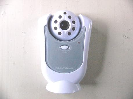
Click to zoom
Application Details
- Equipment Class
- DXX - Part 15 Low Power Communication Device Transmitter
- Date of Grant
- Apr 26, 2005
- Application Purpose
- Original Equipment
- Date of Application
- Apr 26, 2005
- Equipment Note
- 2.4GHz WIRELESS CAMARA
- Frequency Range
- 2410.50000000 - 2472.50000000
- Country
- Canada
Documents & Files
Document Text
Text extracted from the exhibit documents filed with the FCC. Open a document above to read the original.
Users Manual
FOR MORE INFORMATION Before operating the system, please read this manual thoroughly and retain it for future reference. This product broadcasts over public airwaves and its video and audio signals may be intercepted without your consent. 2.4 GHz 1.8”Color TFT LCD Monitor With Wireless Camera SG5550 PORTABLE HOME VIDEO SECURITY SYSTEM Explanation of two Symbols The lightning flash with arrowhead symbol, within an equilateral triangle, is intended to alert the user to the presence of uninsulated"dangerous voltage“within the product's enclosure that may be of sufficient magnitude to constitute a risk of electric shock to persons. The exclamation point within an equilateral triangle is intended to alert the user to the presence of important operating and maintenance(servicing) instructions in the literature accompanying the appliance. THE GRAPHIC SYMBOLS WITH SUPPLEMENTAL MARKING ARE ON THE BOTTOM OF THE SYSTEM. ! WARNING: To prevent fire or shock hazard, do not expose this unit to rain, water, or wet locations. Do not insert any metallic object through the ventilation grills. FCC CLASS B NOTICE Note: This equipment has been tested and found to comply with the limits For a Class B digital device, pursuant to Part 15 of the FCC Rules. These limits are designed to provide reasonable protection against harmful interference in a residential installation. This equipment generates, uses and canradiate radio frequency energy and, if not installed and used in accordance with the instruction, may cause harmful interference to radio communications. However, there is no guarantee that interference will not occur in a particular installation. If this equipment does cause harmful interference to radio or television reception, (which can be determined by turning the equipment off and on), the user is encouraged to try to correct the interference by one or more of the following measures: CAUTION RISK OF ELECTRIC SHOCK. DO NOT OPEN. CAUTION: TO REDUCE THE RISK OF ELECTRIC SHOCK, DO NOT REMOVE COVER (OR BACK). NO USER-SERVICEABLE PARTS INSIDE. REFER SERVICING TO QUALIFIED SERVICE PERSONNEL. ! •Reorient or relocate the receiving antenna •Increase the separation between the monitor and the camera. •Connect the equipment into an outlet on a circuit different from that to which other devices may be connected. •Consult the dealer or an experienced radio or television technician for help. •Please review the troubleshooting section of this manual i SAFETY INSTRUCTIONS IMPORTANT SAFEGUARDS All the safety and operating instructions should be read before the appliance is operated and retained for future reference. 1. HEED WARNINGS -All warnings on the appliance and in the operating instructions should be adhered to. 2. FOLLOW INSTRUCTIONS -All operating instructions should be followed. 3. WATER AND MOISTURE -Do not use this video product near water – for example, a bath tub, wash bowl, kitchen sink, laundry tub or swimming pool, or in a wet basement. 4. POWER SOURCES -This product should be operated only from the type of power source indicated on the marking label. 5. OVERLOADING -Do not overload outlets and extension cords, which can result in a risk of fire or electric shock. 6. SERVICING -Do not attempt to service this product yourself. Opening or removing covers may expose you to dangerous voltage or otherhazards. Refer all servicing or repairs to qualified service personnel. 7. DAMAGE REQUIRING SERVICE -Unplug this product from the wall outlet and refer servicing or repairs to qualified service personnel under the following conditions: a. When the power supply cord or plug is damaged. b. If liquid has been spilled or objects have fallen into the product. c. If the product has been exposed to rain or water. d. If the product does not operate normally by following theoperating instructions. Adjust only those controls that are covered by the operating instructions. e. If the product has been dropped or the cabinet has been damaged. f. When the product exhibits a distinct change in performance. 8. REPLACEMENT PARTS -When replacement parts are required, be sure the service technician has used replacement parts that are specified by the manufacturer or have the same characteristics as the original part. Unauthorized substitutions may result in fire,electric shock, or other hazards. 9. SAFETY CHECK -Upon completion of any service or repairs to this video product, ask the service technician to perform safety checks to determine if the video product is in proper operating condition. 10. An appliance and cart combination should be moved with care. Do not place this equipment on an unstable cart, stand, ortable.The equipment may fall, causing serious injury to a child or adult, and serious damage to the equipment. Wall or shelf mounting should follow the manufacturer's instructions and should be done with a mounting kit approved by the manufacturer. ii TABLE OF CONTENTS iii INTRODUCTION & FEATURES............................................. SYSTEM INCLUDES........................................................... CONTROLS AND FUNCTIONS Monitor Controls –Front Panel .......................................... Monitor Controls –Side Panels ............................................. Camera Controls ........................................................... Docking Station Controls ................................................. INSTALLATION Camera ................................................................................ Monitor .................................................................................... SYSTEM OPERATION Additional camera connection........................................... Alarm Alert .................................................................. Auto & Manual Viewing Options........................................ Auto Scanning............................................................... Selectable Dwell Settings................................................ Connecting The Moni…
Text truncated - open the document above for the full version.
Block Diagram
Applicant: Strategic Vista Technologies Inc. FCC ID: RTMSV05CAM-1 Block Diagram
External Photos
Applicant: Strategic Vista Technologies Inc. FCC ID: RTMSV05CAM-1 EUT top view EUT bottom view
ID Label/Location Info
Applicant: Strategic Vista Technologies Inc. FCC ID: RTMSV05CAM-1 This device complies with Part 15 of the FCC Rules. Operation is subject to the following two conditions: (1) this device may not cause harmful interference, and (2) this device must accept any interference received, including interference that may cause undesired operation. The Label must not be a stick-on paper label. The Label on these products must be permanently affixed to the product and readily visible at the time of purchase and must last the expected lifetime of the equipment not be readily detachable. Proposed Label Location on EUT EUT Bottom View/Proposed FCC ID Label Location FCC ID: RTMSV05CAM-1
Internal Photos
Applicant: Strategic Vista Technologies Inc. FCC ID: RTMSV05CAM-1 EUT inside whole view Main & RF board component side Main & RF board solder side
Operational Description
Applicant: Strategic Vista Technologies Inc. FCC ID: RTMSV05CAM-1 Circuit Description for SV05CAM 2.4G Wireless Transmitter The 2.4G wireless CAM is separate into three parts: 1. Color CMOS image sensor mdoule 2 Transmitter control Portion 3. 2.4G RF transmitter module 1. Color CMOS image sensor module The Color CMOS image sensor is a single chip module. Through the image IC, optical image will transfer to a standard analogue video signal. Which will pass the transmitter control portion. Microphone come with the camera board will convert the voice signal to a audio signal and this audio signal is also pass to the transmitter control portion. 2. Transmitter control portion This portion is mainly for power supply circuitry and signal path. The video and audio signal from the camera module are pass through the control PCB to the 2.4G transmitter module. The power on/off switches on the control PCB control the power supply for the product. The push button on the control PCB allows user to select the right channel frequency and pass the channel selects information to the RF transmitter module. 3. 2.4G RF transmitter module The core of the RF transmitter module is the IC1. IC1 is a single chip PLL frequency synthesizer. Control data from MCU IC2 is entered via the I2C bus, select the oscillator frequency. The output of IC1 is feed to control the Q5 which form a RF mixer circuitry. Video signal from control board is passed to the RF mixed. Audio signal A1 is pass to a modulate circuit Q1 and Q2, which modulate the A1 audio signal to a 6Mhz carrier. An audio channel A2 is pass to a modulate circuitry Q3 and Q4 which modulate the A2 audio signal to a 6.5Mhz carrier. The video signal, together with A1 and A2 signal are entered the RF mixer and through the RF circuitry sent the signal to the dipole antenna to broadcast the signal.
Schematics
Õ◊—Û› ÓÍ Õ◊—Û‹ ÓÈ fl...fiÔÕ ÓË flŸ“‹ Ô fl ‹‹ Ó flfiŒÃ Ì ¤ ‹‹ ÔÓ ¤Ÿ“‹ ÔÌ Õ››fiÛ¤ ÔÏ –»—“⁄‘– ÔÎ »›‘’Ô ÔÍ ‹ ‹‹ ÔË fi’‘Ã Ï »›‘’Ó ÔÈ ıı Ÿ≤º Ó Ÿ“‹ Ó
Test Report
The test report consists 30 pages in total. It may be duplicated completely for legal use with the allowance of the applicant. It shall not be reproduced except in full, without the written approval of Ke Mei Ou Laboratory Corporation. The test result in the report only applied to the tested sample. FCC TEST REPORT Under FCC 15 Subpart C, Paragraph 15.249: 2003 Prepared For : Strategic Vista Technologies Inc. 300 Alden Road, Markham, Ontario Canada, L3R 4C1. March 29, 2005 FCC ID: RTMSV05CAM-1 EUT: 2.4GHz Wireless Camera Model: SV05CAM Report Type: Original Report Test Engineer: Peter Lin Test Date: March 11, 2005 Review By: Apollo Liu / Manager FEDERAL COMMUNICATIONS COMMISSION Registration Number: 125782 INDUSTRY CANADA Registration Number: IC4986 Ke Mei Ou Laboratory Co., Ltd. 7A, Jiaxiangge, Jiahuixincheng, No.3027, Shennan Rd., Futian, Shenzhen, Guangdong, P.R.China. Zip Code: 518033 Tel: + 86 755 83642690 Fax: + 86 755 83297077 www.kmolab.com Strategic Vista Technologies Inc. FCC ID: RTMSV05CAM-1 KMO FCC ID Report Report #: KSZ2005022401J Page 2 of 30 TABLE OF CONTENTS 1. General Information....................................................................................................................................................3 1. 1 Notes......................................................................................................................................................................3 1. 2 Testing Laboratory..................................................................................................................................................3 1. 3 Details of Applicant................................................................................................................................................3 1. 4 Application Details..................................................................................................................................................3 1. 5 Test Item.................................................................................................................................................................3 1. 6 Test Standards.........................................................................................................................................................3 2. Technical Test...............................................................................................................................................................4 2. 1 Summary of Test Results.........................................................................................................................................4 3. EUT Modifications.......................................................................................................................................................4 4. Conducted Power Line Test.........................................................................................................................................5 4. 1 Test Equipment.......................................................................................................................................................5 4. 2 Test Procedure........................................................................................................................................................5 4. 3 Test Setup...............................................................................................................................................................5 4. 4 Configuration of the EUT........................................................................................................................................6 4. 5 EUT Operating Condition........................................................................................................................................7 4. 6 Conducted Power Line Emission Limits..................................................................................................................7 4. 7 Conducted Power Line Test Result...........................................................................................................................8 5. Radiated Emission Test..............................................................................................................................................10 5. 1 Test Equipment.....................................................................................................................................................10 5. 2 Test Procedure......................................................................................................................................................10 5. 3 Radiated Test Setup...............................................................................................................................................10 5. 4 Configuration of the EUT......................................................................................................................................11 5. 5 EUT Operating Condition......................................................................................................................................11 5. 6 Radiated Emission Limit.......................................................................................................................................11 5. 7 Radiated Emission Test Result...............................................................................................................................12 6. Band Edge..................................................................................................................................................................14 6. 1 Test Equipment.....................................................................................................................................................14 6. 2 Test Procedure............................................................................................................................…
Text truncated - open the document above for the full version.
Test Setup Photos
Applicant: Strategic Vista Technologies Inc. FCC ID: RTMSV05CAM-1 Conducted emission test view Radiated emission test view
Contact Information
Applicant
Joel Kligman(President)
Test Firm
Ke Mei Ou Laboratory Co., Ltd.Apollo Liu
Technical Specifications
| # | Rule Parts | Frequency Range | Power Output |
|---|---|---|---|
| 1 | 15C | 2.41 GHz - 2.47 GHz | - |
Other Applications from Strategic Vista Technologies Inc.
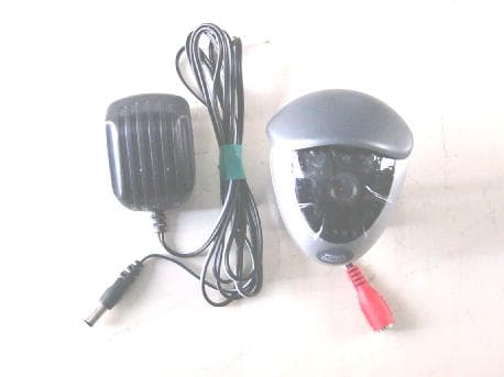
RTMSV06CAM
Aug 03, 20062.4G WIRELESS COLOR CMOS CAMERA
Equipment Class
DXX - Part 15 Low Power Communication Device Transmitter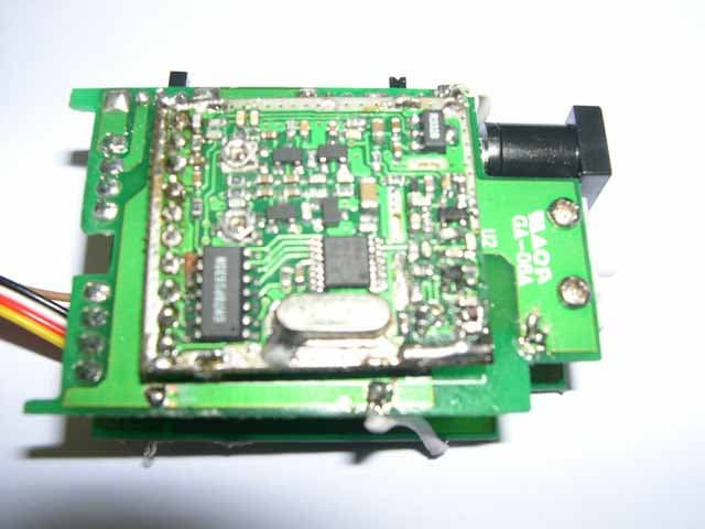
RTMSV-03-CAM
Aug 17, 20042400-24183.5MHz WIRELESS CAMERA-TX
Equipment Class
DXX - Part 15 Low Power Communication Device Transmitter