RTW812272MHz FOUR CHANNEL TRANSMITTER AND RECEIVER
Sirdar Metal & Plastic Works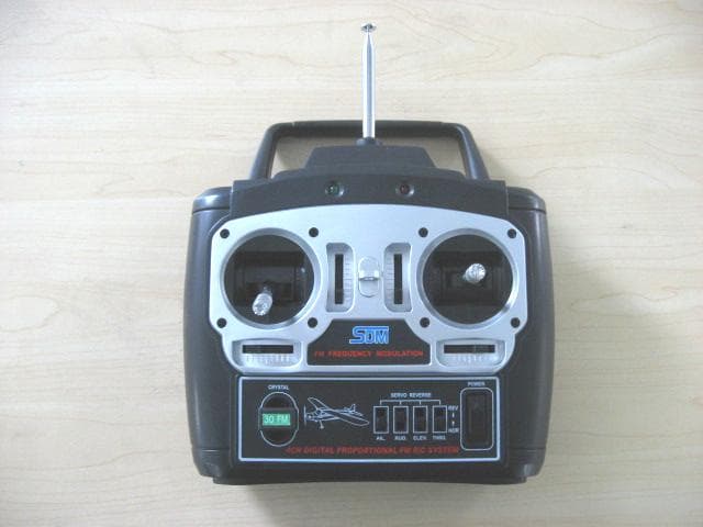
Click to zoom
Application Details
- Equipment Class
- TNB - Licensed Non-Broadcast Station Transmitter
- Date of Grant
- Jan 28, 2007
- Application Purpose
- Original Equipment
- Date of Application
- Jan 27, 2007
- Equipment Note
- 72MHz FOUR CHANNEL TRANSMITTER AND RECEIVER
- Frequency Range
- 72.19000000 - 72.79000000
- Company
- Sirdar Metal & Plastic Works
- Country
- China
Documents & Files
Document Text
Text extracted from the exhibit documents filed with the FCC. Open a document above to read the original.
Users Manual
T4DP-FM T4DP-FM FM4CHDIGITALPROPORTIONALR/CSYSTEMFOR MODELAIRPLANES USERMANUAL MadeInChina Foryoursafetyusing,pleasereadthis manualthoroughly. TECHNICALSPECIFICATIONS: WARNINGANDPRECAUTIONS Type:-----------------------------------------------------T4DP-FM72 Channel:-------------------------------------------------4CH Modulation:----------------------------------------------FM Frequency:----------------------------------------------72MHz WorkingVoltage:--------------------------------------12V WorkingCurrent:---------------------------------------120mA *ReadusermanualcarefullybeforeputtingtheR/Cintouse. *Donotopratethesysteminopencrowd. *Donotopratethissystemwhenmodelsofthesame frequencyareinuse. *Fullyextendtheantennasbeforeoperating. *Removebatteriesafteruse. *Donotmixwitholdandnewbatteries. *Donotmixdifferentbrandsofbatteries. Foryoursafetyusing,pleasereadthis manualthoroughly. SYSTEMCONTENTS: ItemsUnit Piece Transmitter T4DP-FM72 S-17(standard) FM72-4CH Servo Horn Servo Horn Retention Screw Servo Retention Screws 1 1 3 3 3 6 Receiver Servo Parts Checkifyouhavetheaboveitems,otherwise,pleasecontactyourlocal distributorforassistance. Antenna Hook Batterylevelindicator CRYSTAL REVERSINGSWITCH POWERSWITCH TwoLEDdisplaytoindicatebattery voltagelevel.Iftheredledflashes andbeepingsoundgivenout,replace batteries. Intheupperposition, thepoweristurnedon Useforchangingcontrolarmcontroldirection. 1.TRANSMITTER BATTERIESINSTALLATION BatteryCover Receivingantenna Connectingtoreceiver Servohorn Mountingflange Servohornretentionscrew *Removebatterycoveratthe backoftransmitter. *Checkcarefullythepolarity markingsbeforeinserting the8AAalkaliorrechargeable battery(notprovided). *Putbackthebatterycover. BATT.Connecttobattery(4.8~6V) CH.1Connecttoaileronservo CH.2Connecttoelevatorservo CH.3Connecttothrottleservo orspeedcontroller CH.4Connecttorudderservo 2.RECEIVER OUTPUTCONNECTOR 3.SERVO CH.3 CH.4 CH.2 CH.1 BATT. X'TAL RECEIVER FM72-4CH ÃÌ‹–ÛŒøº∑±⁄”ÓÈ”ÿ¶Ú∞≥º –flŸ¤ÎÓÎÛÔÔÛÔÓ STORAGE ASSEMBLY 1.Servo/ReceiverInstallationDiagram 2.ServoHornInstallation PowerSupply (Input(4.8V-6V) ConnecttoaSpeed Controller *Afterconnectingservotoreceiver, turnonthepowerswitchofthe transmitterandreceiver. *Ensurethetrimsontransmitterare atneutralposition. *Installtheservohornaccordingto drawing. *StoretheR/Csysteminoptimalconditions,keepawayfrom extremehotorcoldconditions. *Keepawayfromdustorfilthyenvironments. *Donotdroportampthesystem. CH.3 CH.4 CH.2 CH.1 BATT. X'TAL RECEIVER FM72-4CH Statement: “Changes or modifications not expressly approved by the party responsible for compliance could void the user’s authority to operate the equipment”.
Cover Letter(s)
American Telecommunications Certification Body Inc. 6731 Whittier Ave, McLean, VA 22101 January 15, 2007 RE: FCC ID: RTW8122_ATCB004441 Attention: Stephen Guo I have a few comments on this Application. Please note that further comments may arise in response to answers provided to the questions below. 1. Please note that the internal photos show what appears to be plug-in crystal capability even though the tune up procedure says tuning is done via a “TX module”. Please note that the schematics also show a crystal possibly as the only replacement component. It also appears that the crystal plug-in is fully accessible by the end user by using common everyday tools. Please note that Part 95 clearly states that “Plug-in crystals are not considered modules and must not be accessible to the user.” If the TX modules are in fact a “plug-in frequency determining modules”, please provide a photo of the TX module. If these are not “plug-in frequency determining modules” where each module contains all of the frequency determining circuitry including the oscillator, please show how this plug-in crystal capability is made completely inaccessible to the user, or please verify how the crystal is soldered or otherwise made to be permanent. 2. Please note that if the fundamental is in fact determined by the use of a TX module in which each module contains all of the frequency determining circuitry including the oscillator, please provide test data for each module as required by Part 95.645(b). 3. If the requirements of item 2 are met, please provide a photo of the TX module. 4. Please note that the internal photos do not appear to be the top and bottom of the same board. Please show top and bottom photos of all boards in the device. Please identify the location of Q3, Q5 and Q6 in the photos. 5. In relation to items 1, 2, 3 and 4 please explain how this device meets the requirements of 95.645 6. If this is a digital device please use the correct part 15 notices and cautions. If not, please explain why the 2-condition statement has been changed to state part 95 and please explain why it is placed on the device. 7. Please note that the power limits for part 95 R/C devices is not an ERP or EIRP limit. Please explain how the erp measurements performed meet the transmitter output power requirements of 96.639(b). Please provide the conducted power levels at the antenna terminal for this device. 8. Please explain why ANSI C63.4 test methods were used for the Part 95 licensed device service. 9. Please note that your test report states that you used 47CFR95 (2002). Please note that you MUST use the most recent CFR rule parts. Please recheck and verify that all testing is in complete agreement and accordance with the latest Part 95 as of the date tested (Jan 2007). 10. Please note that depending on the response to the above comments further comments may result. Dennis Ward mailto:[email protected] The items indicated above must be submitted before processing can continue on the above referenced application. Failure to provide the requested information may result in application termination. Correspondence should be considered part of the permanent submission and may be viewed from the Internet after a Grant of Equipment Authorization is issued. Please do not respond to this correspondence using the email reply button. In order for your response to be processed expeditiously, you must submit your documents through the AmericanTCB.com website. Also, please note that partial responses increase processing time and should not be submitted. z Page 2 January 15, 2007 Any questions about the content of this correspondence should be directed to the sender.
Cover Letter(s)
These are not “plug-in frequency determining modules”, the crystal is soldered so it will not accessible to the user. And we have taken the photo of the TX module, the photo is uploaded to the website. The fundamental is determined by the TX module. This product’s frequency range is from 72.19 MHz to 72.79MHz, so it is less than 1MHz, according to FCC part 15 section 15.31 (m), only a middle frequency module was tested. The photo of TX module uploaded to the website. The photos appearing top and bottom of all boards uploaded to web site , and the Q3, Q5, Q6 was identified in the photo with red items. As the crystal is soldered so it will not accessible to the user. So it meets the requirements of 95.645. It is not a digital device, and the revised FCC ID label that removing statement uploaded to web site. We have used a substation method to calculate the power, so the erp measurements performed meet the transmitter output power requirement. The power was calculated by substituted method , so it’s no need to test the conducted power at the antenna. The test methods changed to TIA603, and the amendment report is uploaded to the website. We have used the latest edition in the report, and the amendment report is uploaded to the website. Glad to get your grant instruction, thanks.
Parts List/Tune Up Info
FCC ID: RTW8122 Tune up procedure over power range according to section 2.1033© (9): 1.Adjustment procedure for the transmitter in order to insure it is transmitting at 72MHz. The transmitting frequency is fixed by crystal(72.19,72.21,72.23,72.25,72.27,72.29,72.31,72.33,72.35,72.37,72. 39,72.41,72.43,72.45,72.47,72.49,72.51,72.53,72.55,72.57,72.59,72.61,7 2.63,72.65,72.67,72.69,72.71,72.73,72.75,72.77,72.79MHz) circuit. We set TX module to lock only for crystal circuit. So it is impossible to transmitting other frequencies with crystalset. 2.Tune up the power of the transmitter by modulating. Measured maximum power is 6.9 mW.
Test Report
Report No.: SZEMO061202628RFF(I) Page: 1 of 13 FCC ID: RTW8122 Authorized Signature: Robinson Lo Laboratory Manager This report refers to the General Conditions for Inspection and Testing Services, printed overleaf This report details the results of the testing carried out on one sample. The results contained in this test report do not relate to other samples of the same product. The manufacturer should ensure that all products in series production are in conformity with the product sample detailed in this report. This report may only be reproduced and distributed in full. If the product in this report is used in any configuration other than that detailed in the report, the manufacturer must ensure the new system complies with all relevant standards. Any mention of SGS International Electrical Approvals or testing done by SGS International Electrical Approvals in connection with, distribution or use of the product described in this report must be approved by SGS International Electrical Approvals in writing. Member of the SGS Group (Société Générale de Surveillance) SGS-CSTC Standards Technical Services Ltd. ISSION No.198 Kezhu Road, Science Town Economic& Technology Development District Guangzhou, China 510663 Telephone: +86 (0) 20 8215 5555 Fax: +86 (0) 20 8207 5059 Email: [email protected] FEDERAL COMMUNICATIONS COMMISSION Registration number: 556682 FCC TEST REPORT Application No. : SZEMO061202628RF(SGS SZ NO.: SZTYR061203177/EL) Applicant: SIRDAR METAL & PLASTIC WORKS FCC ID: RTW8122 Fundamental Frequency: 72.19,72.21,72.23,72.25,72.27,72.29,72.31,72.33,72.35,72.37,72.39,72.41, 72.43,72.45,72.47,72.49,72.51,72.53,72.55,72.57,72.59,72.61,72.63,72.65, 72.67,72.69,72.71,72.73,72.75,72.77,72.79MHz♣ ♣ Please refer to section 2 of this report which indicates which Fundamental Carrier Frequency was actually tested. Equipment Under Test (EUT): EUT Name: 72MHz FOUR CHANNEL TRANSMITTER AND RECEIVER Model No.: Labelled Age Grading: Country of Origin: Country of Destination: T4DP-FM72 14yrs & up CHINA USA Standards: FCC Part 95: 2006 Date of Receipt: 29 December 2006 Date of Test: 04 January 2007 Date of Issue: 05 January 2007 Test Result : PASS * * In the configuration tested, the EUT complied with the standards specified above. SGS-CSTC Standards Technical Services Ltd. Report No.: SZEMO061202628RFF(I) Page: 2 of 13 FCC ID: RTW8122 2 Test Summary Test Test Requirement Stanadard Paragraph Result Flied Strength of Fundamental FCC Part 95: 2006 Section 95.639 PASS Flied Strength of Harmornics or other Frequency FCC Part 95: 2006 Section 95.635 PASS Emission Bandwidth FCC Part 95: 2006 Section 95.633 PASS Frequency Stability FCC Part 95: 2006 Section 95.623 PASS ♣ Remark: The fundamental frequencies: 72.19,72.21,72.23,72.25,72.27,72.29,72.31,72.33,72.35,72.37,72.39,72.41, 72.43,72.45,72.47,72.49,72.51,72.53,72.55,72.57,72.59,72.61,72.63,72.65, 72.67,72.69,72.71,72.73,72.75,72.77,72.79MHz Since the same PCBs only use different types of crystals, only 72.39MHz product was completely tested in the whole report. SGS-CSTC Standards Technical Services Ltd. Report No.: SZEMO061202628RFF(I) Page: 3 of 13 FCC ID: RTW8122 3 Contents Page 1 COVER PAGE...........................................................................................................................................1 2 TEST SUMMARY....................................................................................................................................................2 3 CONTENTS..............................................................................................................................................................3 4 GENERAL INFORMATION....................................................................................................................................4 4.1 CLIENT INFORMATION.......................................................................................................................................4 4.2 GENERAL DESCRIPTION OF E.U.T...................................................................................................................4 4.3 DESCRIPTION OF SUPPORT UNITS...................................................................................................................4 4.4 STANDARDS APPLICABLE FOR TESTING...........................................................................................................4 4.5 TEST LOCATION................................................................................................................................................4 4.6 OTHER INFORMATION REQUESTED BY THE CUSTOMER..................................................................................4 5 TEST RESULTS......................................................................................................................................................5 5.1 TEST INSTRUMENTS..........................................................................................................................................5 5.2 E.U.T. OPERATION...........................................................................................................................................5 5.3 TEST PROCEDURE & MEASUREMENT DATA....................................................................................................6 5.3.1 Flied Strength of Fundamental.................................................................................................................6 5.3.2 Flied Strength of Harmornics or other Frequency.................................................................................8 5.3.3 Emission Bandwidth................................................................................................................................11 6 PHOTOGRAPHS - TEST SETUP........................................................ERROR! BOOKMARK NOT DEFINED. 7 PHOTOGRAPHS - EUT CONSTRUCTIONAL DETAILS............ERROR! BOOKMARK NOT DEFINED.-16 SGS-CST…
Text truncated - open the document above for the full version.
Contact Information
Applicant
Tony Lau(Sales Manger)
Technical Specifications
| # | Rule Parts | Frequency Range | Power Output | Emission | Tolerance |
|---|---|---|---|---|---|
| 1 | 95C | 72.19 MHz - 72.79 MHz | 6.90 mW | 8K00FID | 10.8000000000 ppm |
Other Applications from Sirdar Metal & Plastic Works

RTW8121
Mar 20, 2006Remote Control Toy Transmitter
Equipment Class
DXX - Part 15 Low Power Communication Device Transmitter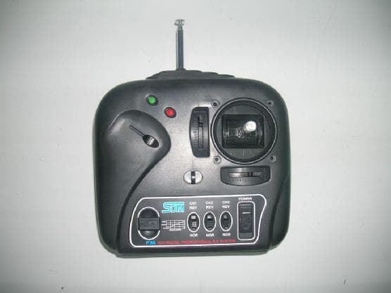
RTW8120
Dec 06, 2005Remote Control
Equipment Class
DXX - Part 15 Low Power Communication Device Transmitter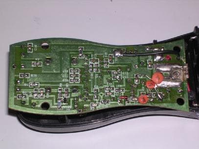
RTW8119
Jun 16, 2004Remote Control Transmitter
Equipment Class
DXX - Part 15 Low Power Communication Device Transmitter
RTW8118
Feb 23, 2004Accipiter Badius RC Toy Transmitter
Equipment Class
DXX - Part 15 Low Power Communication Device Transmitter