RU5AWBSH3BLUETOOTH EARPHONE
Asia Pacific Microsystems, Inc.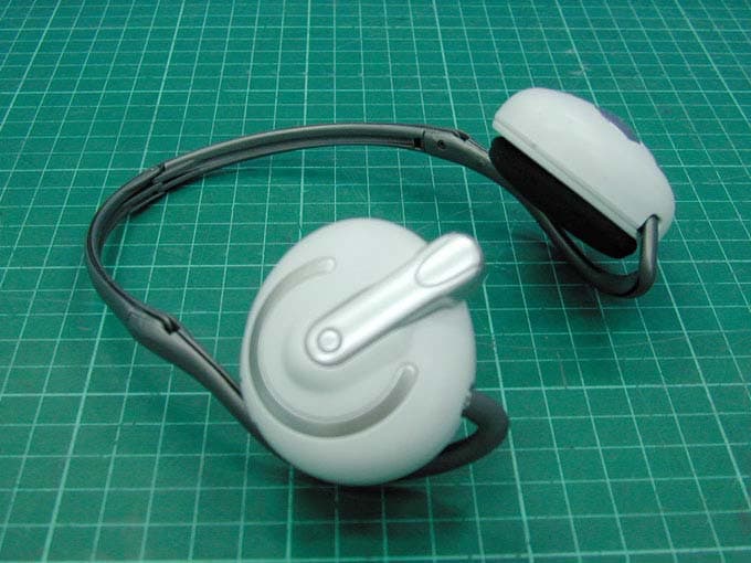
Click to zoom
Application Details
- Equipment Class
- DSS - Part 15 Spread Spectrum Transmitter
- Date of Grant
- Apr 27, 2006
- Application Purpose
- Original Equipment
- Date of Application
- Apr 27, 2006
- Equipment Note
- BLUETOOTH EARPHONE
- Frequency Range
- 2402.00000000 - 2480.00000000
- Country
- Taiwan
Documents & Files
Document Text
Text extracted from the exhibit documents filed with the FCC. Open a document above to read the original.
Users Manual
1 Audio-Mate Stereo Headset With Transmitter User Manual 2 Contents 1.Introduction ................................................ 2.BOX Package ............................................. 3.Getting Started ................................................ 3.1 Preparation ............................................... 3.2 Pairing Headset & Audio Transmitter............... 3.3 How To Use Headset & Audio Transmitter........ 3.4 Current Support Phone List........................... 3.5 The Power Source of the Devices................... 3.5.1 Audio Transmitter Power Source............... 3.5.2 Bluetooth Headset Power........................ 4. Versatile Applications .................................... 5. Warning ...................................................... 3 1. Introduction Length Adjustment Power switch Audio-mate Stereo Headset Transmitter Blue LED Discovery: Fast flash Paired : slow flash Green LED Low battery indicator Red LED Charging indicator Power Switch / Pairing Button Rechargeable batteries with USB connector Hi-Fi Audio in jack 3.5mm Charging port (DC 5V) Charging LED(RED) Volume UP Volume Down Accept/Reject Calls Pairing LED (Blue) 4 2. Package a. Stereo Headset *1b. Audio Transmitter * 1 c. USB Charger cable *1 d. Manual *1 Safety information 1. Don’t use the headset phone and transmitter inside hospitals , airplanes or in the vicinity of other emergency systems. 2. Keep away from the strong radio system, to ensure the signal quality. 3. Continuous listening of music at a high volume may cause damage to your ears. 4. Never use the Bluetooth Headphones whilst driving. Manual Manual Manual Manual 1.Audio-Mate stereo Headset *1 2.Audio Transmitter *1 3.USB Charger Cable *1 4.Manual *1 5 3. Getting Started 3.1 3.1 Preparation Preparation - - Audio Audio - - Mate Headset Mate Headset 1. Please make sure the battery power of headset and the TX is sufficient . 2. If the power is low, following scenarios happen: (1) The headset starts to reset automatically. (2) You can constantly hear breaks on the audio link. (3) You can’t connect the headset to the TX or Dongle after several tries. 3. Please charge the headset when you see the low power condition. When the battery is begin charged, the charging LED indicator of the headset will show red light constantly. 4. When the battery is full , the light of headset or TX will beshut off automatically. - - Transmitter Transmitter •Plug AC Adapter into the DC jack of the Transmitter •Plug the AC Adapter’s plug into the outlet. •The LED indication is Greenwhen charging the Transmitter. •The LED indications turns offAfter the battery is fully charged. •Remove the AC Adapter from Transmitter. 6 Pairing CD/DVD Player NB/PC TVMP3 3.2 3.2 Pairing Audio Pairing Audio - - Mate Headset & Bluetooth Audio Transmitter Mate Headset & Bluetooth Audio Transmitter 1. Turning on the Audio-Mate Headset Power-On Switch, the Power-On LED will start rapid flashingthat is into standby mode for pairing. 2. To start Audio Transmitter by pushing down (about 5s) the Audio Transmitter Power-On Button continuously until LED1flashing (Blue) ; Transmitter is into the pairing mode . 3. which is about 5-10 seconds to complete the pairing process. 4. To complete the pairing process; always check below: a. Audio Transmitter: When Power-On LED Light changes to a steady flashing mode which is about 1 time per second that means the pairing operation is finished. b. Bluetooth Headset: When finishing the pairing process; the Power-On LED will stop flashing and remains on. 7 3.4 Current Support Phone List: Nokia 3650/3660/6230/6600/6820/7610/6310i/N-Gage/7610/6670/6670b/9300/6630 Future:7710/9500 Motorola V600 /V500 /V525 /V80 /A630 /V620 /E550 /V535 /V545 /V550 /V600i/A768i/V3/E398 V710 CDMA 2000 Phone/V3/V330 Future:A780/E680/V547/Matta/V400/V635/A925/A835/E815/M1000/A1010/V2000/MPX200 /MPX100/A860/i603 Sony Ericsson T68i/T610/T630/Z600*/P800/P900/T610/Z600/S700/S700c/K750/V800/W800/S700i/P900 Future: K700 Siemens U15/SX1 Panasonic EB-X70/FJ505 Future: X700 Fujitsu F900iT/FJ505 BlackBarry 7100t Toshiba e8xx/W21T/A5504T Samsung SPH-V6900 Future:SGH-D500/SGH-620/SHG-880/SPH-G1000/SCH-G1000/SGH/Z140/ZGH-D600/SGH-800 PalmOne Treo650 LG Future:PM325 Dopod 565/575/585 Attention 1. If you want to use this function for mobile phone talk and listen, please check the mobile phone has Bluetooth headset function before. 2. Mobile phone makers may have different to pairing procedure between headset and mobile phone. 3. About the pairing procedure between headset and mobile phone , please check the function by your mobile phone users manual. 3.3 3.3 How To Use Bluetooth Headset & Bluetooth Audio Transmitter How To Use Bluetooth Headset & Bluetooth Audio Transmitter 1. To Enable the Bluetooth Function with Your Entertainment Device a. After pairing the Bluetooth Headset and the Audio Transmitter; simply connect the Audio Transmitter to the Entertainment Device via the standard Audio Jack ofthe Audio Transmitter. b. To use Home Entertainment Devices that do not provide Audio In interface: use an Audio Jack to standard RCA cable and then connect it to the Device toenable its Bluetooth function. 2. Listening Mobile Phone a. Please follow the below steps to connect your mobile phone with the Bluetooth Headset: If you wish to use Handsfree function to answer the mobile phone while music playing, please do pair your mobile phone and headset before pairing transmitter and headset. b. Auto sound notify when your mobile phone call in. Push straight inwards to pick up the incoming call & push it again to hang up & recover the music at the same time. Some mobile phone may terminate the music souce while answering the phone call; under such circumstance, reconnect to the music source. 8 3.5 3.5 The Power Source of the Devices The Power Source of the Devices 3.5.1 Audio Transmitter Power Source Audio Transmitter contents an internal rechargeable battery.When battery low, the Battery LED Indicatio…
Text truncated - open the document above for the full version.
Cover Letter(s)
TEL: +886 3 666 1188 FAX: +886 3 666 1199 Web Site: www.apmsinc.com Confidentility Letter (Permanent) Attention: Application Examiner Re: Request for confidentiality Applicant: Asia Pacific Microsystems, Inc. FCC ID: RU5AWBSH3 To whom it may concern, Request is hereby submitted by Asia Pacific Microsystems, Inc. to withhold permanently from public review certain portions of the application for equipment certification for the referenced FCC identifiers. This request for confidentiality is made pursuant to 47 CFR 0.457(d) of the FCC Rules. In particular, the following sections of the application are to be kept permanently confidential: • Schematics • Detailed Block diagrams • Detailed Operational/Functional Description Rationale for request for confidentiality: Asia Pacific Microsystems, Inc. has invested considerable time and materials in research and development to produce the referenced product. Disclosure of the permanently confidential portions of this application to competitors would not only give them significant competitive advantages in developing similar products, but would also disclose successful implementation of unpublished, leading edge technology developed by us. If you have questions or need further information, please contact the undersigned. Sincerely, Henry Kao Senior Engineer Asia Pacific Microsystems, Inc.
External Photos
Photo 1: External photo of EUT AW B S H 3 Photo 2: External photo of EUT AW B S H 3 Photo 3: External photo of EUT AW B S H 3
Internal Photos
Photo 1: Internal photo of EUT AW B S H 3 Photo 2: Internal photo of EUT AW B S H 3 Photo 3: Internal photo of EUT AW B S H 3 Photo 4: Internal photo of EUT AW B S H 3 Photo 5: Internal photo of EUT AW B S H 3 Photo 6: Internal photo of EUT AW B S H 3
Test Report
FCC ID. : RU5AWBSH3 Report No.: EME-051133 Page 1 of 34 EMC TEST REPORT Report No. : EME-051133 Model No. : AWBSH3 Issued Date : Apr. 20, 2006 Applicant : Asia Pacific Microsystems, Inc. No. 2, R&D Road 6, Science-Based Industrial Park, Hsinchu, Taiwan Test By : Intertek Testing Services Taiwan Ltd. No. 11, Lane 275, Ko-Nan 1 Street, Chia-Tung Li, Shiang-Shan District, Hsinchu City, Taiwan This test report consists of 34pages in total. It may be duplicated completely for legal use with the allowance of the applicant. It shall not be reproduced except in full, without the written approval of Intertek Laboratory. The test result(s) in this report only applies to the tested sample(s). Kevin Chen Project Engineer Reviewed By Jerry Liu FCC ID. : RU5AWBSH3 Report No.: EME-051133 Page 2 of 34 Table of Contents Summary of Tests ..............................................................................................................4 1. General information ......................................................................................................5 1.1 Identification of the EUT ........................................................................................5 1.2 Additional information about the EUT....................................................................5 1.3 Antenna description.................................................................................................6 1.4 Peripherals equipment .............................................................................................6 2. Test specifications .........................................................................................................7 2.1 Test standard............................................................................................................7 2.2 Operation mode .......................................................................................................7 2.3 Test equipment ........................................................................................................8 3. 20dB Bandwidth test .....................................................................................................9 3.1 Operating environment............................................................................................9 3.2 Test setup & procedure............................................................................................9 3.3 Measured data of modulated bandwidth test results ...............................................9 4. Carrier Frequency Separation test ...............................................................................11 4.1 Operating environment..........................................................................................11 4.2 Test setup & procedure..........................................................................................11 4.3 Measured data of Carrier Frequency Separation test result ..................................11 5. Number of hopping frequencies test ...........................................................................13 5.1 Operating environment..........................................................................................13 5.2 Test setup & procedure..........................................................................................13 5.3 Measured data of number of hopping frequencies test result................................13 6. Time of Occupancy (dwell time) test ..........................................................................15 6.1 Operating environment..........................................................................................15 6.2 Test setup & procedure..........................................................................................15 7. Maximum Output Power test ......................................................................................19 7.1 Operating environment..........................................................................................19 7.2 Test setup & procedure..........................................................................................19 7.3 Measured data of Maximum Output Power test results ........................................19 8. Radiated Emission test ................................................................................................20 8.1 Operating environment..........................................................................................20 8.2 Test setup & procedure..........................................................................................20 FCC ID. : RU5AWBSH3 Report No.: EME-051133 Page 3 of 34 8.3 Emission limits ......................................................................................................21 8.4 Radiated spurious emission test data.....................................................................22 8.4.1 Measurement results: frequencies equal to or less than 1 GHz..........................22 8.4.2 Measurement results: frequency above 1GHz ...................................................23 9. Emission on the band edge §FCC 15.247(C) ..............................................................24 9.1 Band-edge (Conducted method)............................................................................25 9.2 Band-edge (Radiated method)...............................................................................27 10. Power Line Conducted Emission test §FCC 15.207 .................................................31 10.1 Operating environment........................................................................................31 10.2 Test setup & procedure........................................................................................31 10.3 Emission limit .....................................................................................................32 10.4 Uncertainty of Conducted Emission ...................................................................32 10.5 Power Line…
Text truncated - open the document above for the full version.
Test Setup Photos
Photo 1: Conducted Emission Test Set-up photo AW B S H 3 Photo 2: Conducted Emission Test Set-up photo AW B S H 3
Test Setup Photos
Photo 1: Radiated Emission Test set-up photo AW B S H 3 Photo 2: Radiated Emission Test set-up photo AW B S H 3
Contact Information
Applicant
John Young(Engineer)
Test Firm
Intertek Testing Services Taiwan Ltd.Alpha Liu
Technical Specifications
| # | Rule Parts | Frequency Range | Power Output |
|---|---|---|---|
| 1 | 15C | 2.40 GHz - 2.48 GHz | 1.20 mW |
Other Applications from Asia Pacific Microsystems, Inc.
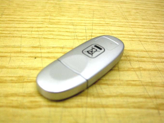
RU5AWBC1E
May 23, 2006Bluetooth V.1.2 Class 1 USB Dongle
Equipment Class
DSS - Part 15 Spread Spectrum Transmitter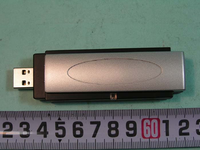
RU5AWGB3U
Mar 29, 2006802.11g WLAN+BlueTooth V1.2 Class 2 USB Dongle
Equipment Class
DTS - Digital Transmission System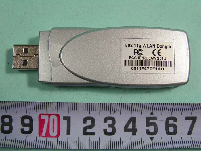
RU5AWG02U
Mar 26, 2006802.11g 54Mbps WLAN 2 USB Dongle
Equipment Class
DTS - Digital Transmission System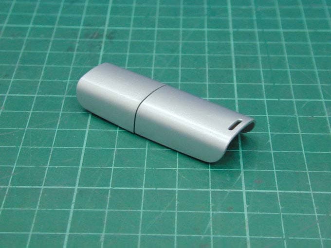
RU5AWBC2E
Dec 19, 2005Bluetooth Dongle
Equipment Class
DSS - Part 15 Spread Spectrum Transmitter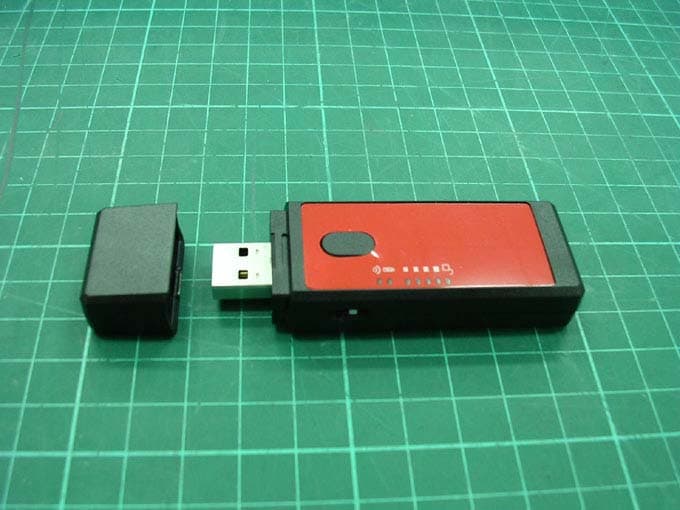
RU5AWGS1U
Nov 28, 2005802.11g WLAN USB Dongle
Equipment Class
DTS - Digital Transmission System