RUSHPSWireless Serial Transceiver
HandyWave Co., Ltd.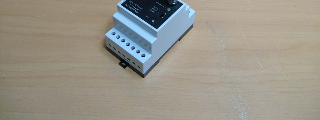
Click to zoom
Application Details
- Equipment Class
- DSS - Part 15 Spread Spectrum Transmitter
- Date of Grant
- Mar 21, 2007
- Application Purpose
- Original Equipment
- Date of Application
- Mar 14, 2007
- Equipment Note
- Wireless Serial Transceiver
- Frequency Range
- 2402.00000000 - 2480.00000000
- Company
- HandyWave Co., Ltd.
- Country
- South Korea
Documents & Files
Document Text
Text extracted from the exhibit documents filed with the FCC. Open a document above to read the original.
Users Manual
User’s Manual HPS Introduction HandyWave Co., Ltd. 1/5 202-4 Yatap-dong, Bundang-gu, Seongnam City, Gyunggi Province 463-070, Republic of Korea Tel: 82-31-709-8900, Fax: 82-31-708-9455 http://www.handywave.com 2006 HandyWave Co., Ltd. All rights reserved. Introduction The HPS from HandyWave is a ready-to-use short-range wireless connectivity solution for industrial. It provides the most economic and powerful way of cable replacement for the serial communication systems including RS-232, RS-422, and RS-485. Features z Supports DIN-RAIL and Wall Mount z Supports Bluetooth Serial Port Profile and Generic Access Profile z No need of external host and software z Easy of installation and use z Supports configuration of the local device z Supports configuration of the remote device via Over-the-Air z Easy of maintenance z Supports up to 100 meter (Line of Sight) z Supports RS-232, RS-422, and RS-485 z Supports Point-to-Point and Point-to-Multipoint Topology Specifications z Standard: Bluetooth Specification Version 1.2 and/or above z Operation Frequency: 2.4GHz ISM Band z Transmitted Power: Max 12.4dBm (Conducted) z Received Sensitivity: More than –80dBm z Power Supply: DC +5 ~ +30V z Current Consumption: Up to 200mA at DC 5V z Operation Temperature: -20 ~ 60 °C z Dimension: 52.5mm (W) x 86.0mm (D) x 58.0mm (H) z Baud Rate: 1.2, 2.4, 4.8, 9.6, 19.2, 38.4, 57.6, and 115.2Kbps z Antenna Interface: Left-handed SMA Female Connector z Signal Interface: 14 Terminals and screws Contents z HPS 2 EA z Antenna 2 EA z A User’s Manual User’s Manual HPS Hardware Setup HandyWave www.handywave.com 2/5 Hardware Setup Interface Items Description Figure ANT Antenna Interface OPR/LNK LED Display RS-232 RS-422 RS-485 Operation Selection Switch for RS-232, RS-422, or RS-485 RST Configuration Button Pin # Signal Direction Descriptions 1 TxD O 1 TxD for RS-232 2 RxD I 2 RxD for RS-232 3 RTS/DTR O RTS/DTR for RS-232 4 CTS/DSR I CTS/DSR for RS- 232 5 GND Common Signal Ground 6 GND Common Power Ground 7 Power I Power Supply 8 TX+/TRX+ I/O TX+: RS-422 TRX+: RS-485 9 TX-/TRX- I/O RX-: RS-422 TRX-: RS-485 10 RX+ I RX+: RS-422 11 RX- I RX-: RS-422 12 GND Common Signal Ground 13 EoR+ O End of Resistor 3 + RS-485 Only 14 EoR- I End of Resistor – RS-485 Only Quick Installation Guide Step 1: Assemble a provided antenna to the antenna port on the HandyPort. Step 2: Select a serial interface using the operation selection switch on the HandyPort. Step 3: Make connections using 14 terminals and screws for power and serial interface. Step 4: Configure the HandyPort, if necessary. 1 O: Output 2 I: Input 3 End of Resistor: If the HandyPort is required an end of resistor, you can make a loop between EoR+ and EoR-. It is only for RS-485. User’s Manual HPS Hardware Setup HandyWave www.handywave.com 3/5 Connection Overview for Power and Serial Interfaces Power Pin # Signal Descriptions 6 GND Power Ground 7 Power Power Supply (DC +5V ~ +30V) RS-232 Items Location Figure Switch RS-232 Pin # Signal Direction Remarks 1 TxD O 1 2 RxD I 2 3 RTS/DTR O 4 CTS/DSR I Please see the below. 3 5 GND Common RS-422 Items Location Figure Switch RS-422 Pin # Signal Direction Remarks 8 TX+ TX+ 9 TX- TX- 10 RX+ RX+ 11 RX- RX- 12 GND GND RS-485 Items Location Figure Switch RS-422 Pin # Signal Direction Remarks 8 TRX+ I/O 9 TRX- I/O 12 GND Common 13 EoR+ O 14 EoR- I Please see the below. 4 1 O: Output 2 I: Input 3 Flow Control (RTS/CTS and/or DTR/DSR): You can use the flow control for RS-232. To use the flow control, you have to set the flow control for the HandyPort and DTE accordingly. 4 EoR (End of Resistor): If the HandyPort is required an end of resistor, you can make a loop between EoR+ and EoR-. It is only for RS-485. User’s Manual HPS Configuration HandyWave www.handywave.com 4/5 Configuration You can change the configuration of HandyPort using HyperTerminal or similar terminal emulator. HyperTerminal Settings z COM Port Settings: 9600 8-N-1, Flow Control: None (Factory Settings of HandyPort) z Emulation: VT100 Switch Location To configure the HandyPort, the switch location shall be in RS-232. Start Configurations Step 1: Make a RS-232 connection between the PC and HandyPort. And supply power for HandyPort. Step 2: Open a Hyper Terminal at the PC and set it up. Step 3: Push the RST button on HandyPort. If you enter the configuration mode successfully, LNK LED will be flashing every second. Step 4: Hit the <Enter> key, 5 second later. Step 5: Change the configuration of HandyPort with commands, if necessary. Usage Printing If you are in the configuration mode, type “?<Enter>” for listing commands. If you want to know the usage of specific command, type “?[command]<Enter>”. All commands and parameters are case sensitive. Therefore, you have to use the capital letter for commands and parameters. End Configurations After finishing the configuration, you have to execute a command “X” to apply changes and exit the configuration mode. Frequently Used Commands Command Syntax Description A ABD_ADDR<CR> Change the remote device address B BBR[D]<CR> Change the baud rate M MMode<CR> Change the connection mode P PPA[D]<CR> Change the parity bit S SST[D]<CR> Change the stop bits V V Display the device information User’s Manual HPS Configuration HandyWave www.handywave.com 5/5 Note. This device complies with Part 15 of the FCC Rules. Operation is subject to the following two conditions: (1) This device may not cause harmful interference, and (2) this device must accept any interference received, including interference that may cause undesired operation. Note. Modifications not expressly approved by this company could void the user’s authority to operate the equipment. Note. This equipment has been tested and found no comply with the limits for a Class B digital device, pursuant to part 15 of the FCC rules. These limits are designed to provide reasonable protection against harmful interference in a residential installation. This equipment generates, uses and can radia…
Text truncated - open the document above for the full version.
Cover Letter(s)
HandyWave Co., Ltd. 202-4 Yatap-dong, Bundang-gu, Seongnam City, Gyunggi Province 463-070, Republic of Korea Tel: 82-31-709-8900, Fax: 82-31-708-9455 http://www.handywave.com March 12, 2007 Federal Communications Commission Equipment Authorization Branch 7435 Oakland Mills Road Columbia, MD 21046 In re : HandyWave Co., Ltd. FCC ID : RUSHPS Request for Confidentiality Gentlemen: Pursuant to Sections 0.457 and 0.459 of the Commission’s Rules, we hereby request confidential treatment of information accompanying this application as outlined below: Schematics (File name: [RUSHPS] SCH.pdf), Parts list(File name: [RUSHPS] PL.pdf), Block diagram (File name: [RUSHPS] BLK.pdf) and Operational description (File name: [RUSHPS] OpDes.pdf). The above materials contain trade secrets and proprietary information not customarily released to the public. The public disclosure of these materials may be harmful to the applicant and provide unjustified benefits to its competitors. The applicant understands that pursuant to Section 0.457 of the Rules, disclosure of this application and all accompanying documentation will not be made before the date of the Grant for this application. Sincerely, Jeong-Jin Choi Director
External Photos
Model No.: HPS FCC ID: RUSHPS Copyright ○ c 2007, LTA Co., Ltd. Page 1 of 1
ID Label/Location Info
Model No.: HPS FCC ID: RUSHPS Copyright Ⓒ 2007, LTA Co., Ltd. SAMPLE LABEL & LOCATION Label
Internal Photos
FCC ID: RUSHPS Copyright ○ c 2007, LTA Co., Ltd. Page 1 of 4 FCC ID: RUSHPS Copyright ○ c 2007, LTA Co., Ltd. Page 2 of 4 FCC ID: RUSHPS Copyright ○ c 2007, LTA Co., Ltd. Page 3 of 4 FCC ID: RUSHPS Copyright ○ c 2007, LTA Co., Ltd. Page 4 of 4
RF Exposure Info
ATTACHMENT FCC ID: RUSHPS ** MPE Calculations ** The EUT will only be used with a separation of 20 centimeters or greater between the antenna and the body of the user. The MPE calculation for this exposure is shown below. The peak radiated output power (EIRP) is calculated as follows: EIRP = P + G EIRP = 12.42 dBm + 2dBi EIRP = 14.42dBm Where, P = Power input to the antenna (mW) G = Power gain of the antenna (dBi) Power density at the specific separation: S = PG/(4R 2 π) S = (17.46 * 1.58) / (4 * 20 2 * π) S = 0.0055 mW/cm 2 Where, S = Maximum power density (mW/cm 2 ) P = Power input to the antenna (mW) G = Numeric power gain of the antenna R = Distance to the center of the radiation of the antenna (20cm = limit for MPE) The Maximum permissible exposure (MPE) for the general population is 1 mW/cm 2 . The power density at 20cm does not exceed the 1 mW/cm 2 limit. Therefore, the exposure condition is compliant with FCC rules. Estimated safe separation: R = √(PG / 4π) R = √(17.46 * 1.58 / 4π) R = 1.48 Cm Where, P = Power input to the antenna (mW) G = Numeric power gain of the antenna R = Distance to the center of the radiation of the antenna (20cm = limit for MPE) The numeric gain(G) of the antenna with a gain specified in dB is determined by: G = Log -1 (dB antenna gain / 10) G = Log -1 (1.98 / 10) G = 1.58
Test Report
Ref. No.: LR500190703C Copyright ○ c 2007, LTA Co., Ltd. Page 1 of 54 243 Jubug-Ri,Yangji-Myeon, Yongin-Si, Gyeonggi-Do, Korea 449-822 Tel: +82-31-323-6008 Fax: +82-31-323-6010 http://www.ltalab.com CERTIFICATIO OF COMPLIANCE FCC ID. APPLICANT FCC Classification : FHSS Sequence Spread Spectrum (FHSS) Manufacturing Description : Wireless Serial Transceiver Manufacturer : HandyWave Co., Ltd. Model name : HPS Test Device Serial No.: : Identical prototype Rule Part(s) : FCC Part 15.247 Subpart C; ANSI C-63.4-2003 Frequency Range : 2402 ~ 2480MHz RF power : 12.42dBm - Conducted Data of issue : March 12, 2007 This test report is issued under the authority of: The test was supervised by: Dong –Min JUNG, Technical Manager Kyung-Taek LEE, Test Engineer This test result only responds to the tested sample. It is not allowed to copy this report even partly without the allowance of the test laboratory. This report must not be used by the applicant to claim product endorsement by any agency. NVLAP LAB Code.: 200723-0 Dates of Tests: March 2 ~ 9, 2007 Test Report S/N: LR500190703C Test Site : LTA CO., LTD. RUSHPS HandyWave Co., Ltd. Ref. No.: LR500190703C Copyright ○ c 2007, LTA Co., Ltd. Page 2 of 54 TABLE OF CONTENTS 1. GENERAL INFORMATION’S -------------------------------------------------------------------------- 2. INFORMATION’S ABOUT TEST ITEM ------------------------------------------------------------- 3. TEST REPORT --------------------------------------------------------------------------------------------- 3.1 SUMMARY OF TESTS ------------------------------------------------------------------------------ 3.2 TECHNICAL CHARACTERISTICS TEST ------------------------------------------------------- 3.2.1 CARRIER FREQUENCY SEPARATION ---------------------------------------------------- 3.2.2 NUMBER OF HOPPING FREQUENCIES -------------------------------------------------- 3.2.3 20 dB BANDWIDTH ---------------------------------------------------------------------------- 3.2.4 TIME OF OCCUPANCY (Dwell Time) ------------------------------------------------------- 3.2.5 TTANSMITTER OUTPUT POWER ---------------------------------------------------------- 3.2.6 BAND – EDGE (Conducted) ------------------------------------------------------------------- 3.2.7 BAND - EDGE (Radiated) ----------------------------------------------------------------------- 3.2.8 FIELD STRENGTH OF HARMONICS ------------------------------------------------------ 3.2.9 AC CONDUCTED EMISSIONS -------------------------------------------------------------- APPENDIX APPENDIX TEST EQUIPMENT USED FOR TESTS ------------------------------------------- 3 4 5 5 6 6 8 13 16 19 22 36 45 48 53 Ref. No.: LR500190703C Copyright ○ c 2007, LTA Co., Ltd. Page 3 of 54 1. General information’s 1-1 Test Performed Company name : LTA Co., Ltd. Address : 243, Jubug-ri,Yangji-Myeon,Youngin-Si, Kyunggi-Do, Korea. 449-822 Web site : http://www.ltalab.com E-mail : [email protected] Telephone : +82-31-323-6008 Facsimile +82-31-323-6010 Quality control in the testing laboratory is implemented as per ISO/IEC 17025 which is the “General requirements for the competents of calibration and testing laboratory”. 1-2 Accredited agencies LTA Co., Ltd. is approved to perform EMC testing by the following agencies: Agency Country Accreditation No. Validity Reference NVLAP U.S.A 200723-0 2007-09-30 ECT accredited Lab. RRL KOREA KR0049 2007-07-13 EMC accredited Lab. FCC U.S.A 610755 2008-03-28 FCC filing VCCI JAPAN R2133, C2307 2008-06-22 VCCI registration IC CANADA IC5799 2008-04-23 IC filing Ref. No.: LR500190703C Copyright ○ c 2007, LTA Co., Ltd. Page 4 of 54 2. Information’s about test item 2-1 Client & Manufacturer Company name : HandyWave Co., Ltd. Address : 202-4 Yatap-dong, Bundang-gu, Seongnam City, Kyunggi Province, 463-070, Korea TEL / FAX : +82-31-709-8900/ +82-31-708-9455 2-2 Equipment Under Test (EUT) Trade name : Wireless Serial Transceiver FCC ID : RUSHPS Model name : HPS Serial number : Identical prototype Date of receipt : February 15, 2007 EUT condition : Pre-production, not damaged Antenna type : Dipole Antenna Max Gain 2.0dBi (Left-handed SMA Connector) Frequency Range : 2402 ~ 2480MHz RF output power : 12.42 dBm - Conducted Number of channels : 79 Duty cycle : 78.2 % Channel spacing : 1MHz Channel Access Protocol : Frequency Hopping Type of Modulation : GFSK Power Source : 5 ~ 30VDC by Main system 2-3 Tested frequency LOW MID HIGH Frequency (MHz) 2402 2441 2480 2-4 Ancillary Equipment Equipment Model No. Serial No. Manufacturer Notebook Latitude D505 8N29F1S DELL - - - - Ref. No.: LR500190703C Copyright ○ c 2007, LTA Co., Ltd. Page 5 of 54 3. Test Report 3.1 Summary of tests FCC Part Section(s) Parameter Limit Test Condition Status (note 1) 15.247(a) Carrier Frequency Separation > 25 kHz C 15.247(a) Number of Hopping Frequencies > 15 hops C 15.247(a) 20 dB Bandwidth < 1 MHz C 15.247 Dwell Time < 0.4 seconds C 15.247(b) Transmitter Output Power < 1Watt C 15.247(d) Conducted Spurious emission > 20 dBc C 15.247(d) Band Edge > 20 dBc Conducted C 15.247(d) Band Edge < 54 dBuV (at 3m) C 15.249 / 15.209 Field Strength of Harmonics < 54 dBuV (at 3m) Radiated C 15.207 /15.107 AC Conducted Emissions EN 55022 Line Conducted C Note 1: C=Complies NC=Not Complies NT=Not Tested NA=Not Applicable Note 2: The data in this test report are traceable to the national or international standards. The sample was tested according to the following specification: FCC Parts 15.247; ANSI C-63.4-2003 Ref. No.: LR500190703C Copyright ○ c 2007, LTA Co., Ltd. Page 6 of 54 3.2 Transmitter requirements 3.2.1 Carrier Frequency Separation Procedure: The carrier frequency separation was measured with a spectrum analyzer connected to the antenna terminal, while EUT had its hopping function enabled. After the trace being stable, the reading value between the peaks of the adjacent channels using the marker-delta function was recorded as the measurement results. The spectrum analyzer is set to:…
Text truncated - open the document above for the full version.
Test Setup Photos
Model No.: HPS FCC ID: RUSHPS Copyright ○ c 2007, LTA Co., Ltd. Page 1 of 2 Radiated Emission Model No.: HPS FCC ID: RUSHPS Copyright ○ c 2007, LTA Co., Ltd. Page 2 of 2 Conducted Emission
Contact Information
Applicant
J. J. Choi(Chief Engineer)
Test Firm
LTA Co.,LtdAhn Chulho
Technical Specifications
| # | Rule Parts | Frequency Range | Power Output |
|---|---|---|---|
| 1 | 15C | 2.40 GHz - 2.48 GHz | 17.00 mW |
Other Applications from HandyWave Co., Ltd.
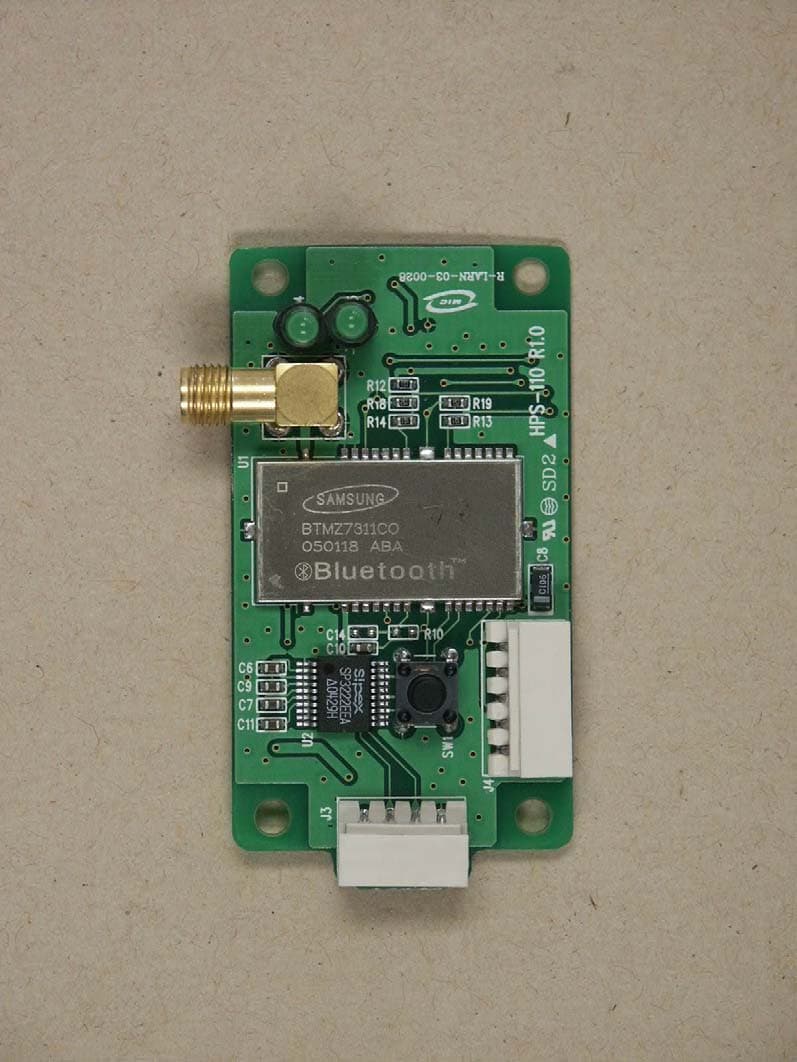
RUSHPS-110
Apr 10, 20052.4GHz Transceiver Module
Equipment Class
DSS - Part 15 Spread Spectrum Transmitter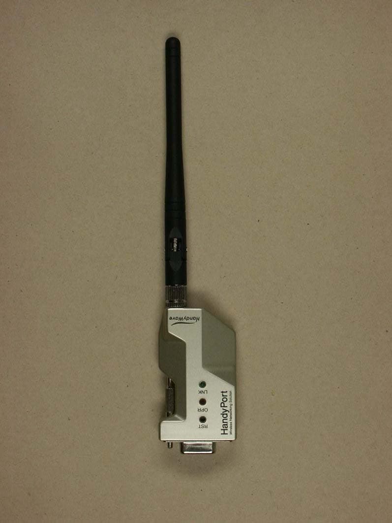
RUSHPS-120
Feb 24, 2004Wireless Serial Adapter
Equipment Class
DSS - Part 15 Spread Spectrum Transmitter