RV6HT640VHF marine transceiver
Entel UK Limited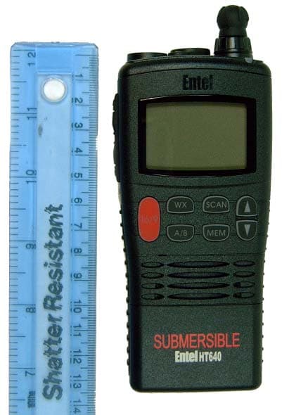
Click to zoom
Application Details
- Equipment Class
- TNF - Licensed Non-Broadcast Transmitter Held to Face
- Date of Grant
- Jun 08, 2004
- Application Purpose
- Original Equipment
- Date of Application
- Jun 08, 2004
- Equipment Note
- VHF marine transceiver
- Frequency Range
- 156.00000000 - 163.00000000
- Company
- Entel UK Limited
- Country
- United Kingdom
Documents & Files
Document Text
Text extracted from the exhibit documents filed with the FCC. Open a document above to read the original.
Users Manual
FOR USA VERSION:- SAFETY TRAINING INFORMATION WARNING. Your Entel radio generates RF electromagnetic energy during transmit mode. This radio is designed for and classified as “Occupational Use Only”, meaning it must be used only during the course of employment by individuals aware of the hazards, and the ways to minimize such hazards. This radio is NOT intended for use by the “General Population” in an uncontrolled environment. Use only Entel approved accessories. Use of accessories other than those specified may result in RF exposure levels exceeding the FCC requirements for wireless RF exposure. CAUTION. To ensure that your exposure to RF electromagnetic energy is within the FCC allowable limits for occupational use, always adhere to the following guidelines:- DO NOT operate the radio without a proper antenna attached, as this may damaged the radio and may also cause you to exceed FCC RF exposure limits. A proper antenna is the antenna supplied with this radio by the manufacturer or antenna specifically authorized by the manufacturer for use with this radio. DO NOT transmit for more than 50% of total radio use time (“50% duty cycle”). Transmitting more than 50% of the time can cause FCC RF exposure compliance requirements to be exceeded. The radio is transmitting when the “TX indicator” lights red. You can cause the radio to transmit by pressing the “PTT” switch. ALWAYS keep the antenna at least 2.5 cm (1 inch) away from the body when transmitting and only use approved accessories to ensure FCC RF exposure compliance requirements are not exceeded. To provide the recipients of your transmission the best sound quality, hold the transceiver at least 5 cm (2 inches) from your mouth, and slightly off to one side. The information listed above provides the user with the information needed to make him or her aware of RF exposure, and what to do to ensure that this radio operates within the FCC RF exposure limits. Electromagnetic Interference/Compatibility During transmissions, your Entel radio generates RF energy that can possibly cause interference with other devices or systems. To avoid such interference, turn off the radio in areas where signs are posted to do so. DO NOT operate the transmitter in areas that are sensitive to electromagnetic radiation such as hospitals, aircraft, and blasting sites. Occupational/Controlled Use The radio transmitter is used in situations in which persons are exposed as a consequence of their employment. These persons should be made fully aware of the potential for exposure so they can exercise control over their exposure. Changes or modifications to this device, not expressly Approved by Entel UK could invalidate your authority to operate this device under FCC regulations.
External Photos
Date:Signed: Entel UK Limited HT640 Front View
External Photos
HT640 Rear View HT640 Top view Date:Signed: Entel UK Limited
External Photos
Date:Signed: Entel UK Limited HT640 SideView
External Photos
CAT640 Antenna for HT640
ID Label/Location Info
HT640 Labe l 'A'
Internal Photos
Date:Signed: Entel UK Limited HT640 Internal Front View
Internal Photos
4 Entel UK -London 2. INTERNAL VIEWS z MAIN UNIT BOTTOM VIEW TOP VIEW
RF Exposure Info
1 Hilton Carr Subject: FW: B3 Requirements -----Original Message----- From: Hilton Carr [mailto:[email protected]] Sent: 12 February 2004 16:41 To: Mark Heaven (E-mail) Subject: B3 Requirements Mark , I have reviewed the previous e-mails and given further consideration over the issue of SAR. In consideration that the maximum power level is 5W at 162 MHz; the equipment is press-to-talk giving a resultant duty factor of 50%; that the equipment will be installed in a Occupational Use environment; that the equipment will be operated >= 2.5 CMs from the head I have concluded that it falls below the "low" threshold for SAR evaluation and consequently does not require SAR evaluation. Best Regards Hilton Carr Task Manager, Certification and Technical Development On behalf of BABT TCB (UK0004) BABT, an accredited UK Certification/Notified Body and company of TÜV Product Service Ltd., 34 Molesey Road - Walton-on-Thames - Surrey - KT12 4RQ - UK Direct Tel: +44 (0) 1932 251227 Fax: +44 (0) 1932 251201 Email: [email protected] This e-mail and any files transmitted with it are confidential and intended solely for the use of the individual or entity to whom they are addressed. A list of the Companies covered by this statement is available from our registered office at: Segensworth Road, Fareham, Hants PO15 5RH. ********************************************************************* To get instant pricing information on TUV PS/BABT services, visit our estimating / quotation system at http://www.online-estimating.com *********************************************************************
Test Report
1 610, Unitechvill, 1141-2, BaeSuk-Dong, IlSan-Gu, GoYang City, GyeongGi-Do, SouthKorea Tel : +82-31-813-1090 Fax :+82-31-813-1093 E-Mail : [email protected] Tests commissioned by Entel UK Limited for FCC approval. Unit tested: HT640 Serial number 95E200046 Some of the data used in this report has been taken from ETSI test report number HT640/1.3 prepared by Naun Telecom, Seoul, Korea. Tests carried out according to 47CFR part 80 Stations in the Maritime Services Tests completed 26 th January 2004 Report amended 24 th May 2004 Signed:- SahngBok Yi Quality Manager 2 The HT640 is a handheld, 5-watt, VHF, frequency modulated transceiver intended for applications in the 156-163MHz marine band. General information. (Paragraph 2.1033 of the rules) 1. Applicant: Entel UK Limited 2. Identification of equipment: FCC ID: RV6HT640 a. The equipment identification label is submitted separately. b. Photographs of the equipment are submitted separately. 3. Quantity production is being carried out for the European marked. 4. Technical description: a. 16K0G3E emission Frequency range 156.000 – 163.275MHz. b. Operating power of the transmitter is fixed at the factory at 5 Watts with a 1 Watt low power setting. d. Maximum power permitted under part 80 of the FCC Rules is 25 Watts, with capability to reduce, readily, to one Watt maximum. The HT640 meets both of these requirements. e. The DC voltage and DC current at the final amplifier: Drain voltage: 7.4Vdc Drain current: 1.6A f. Function of each active semiconductor device: See Appendix 1. g. Complete circuit diagram: See service manual - separate exhibit. h. Instruction book is submitted separately. i. Transmitter set up procedure: See service manual separate exhibit. j. A description of circuits for stabilising the frequency is included in appendix 2. k. A description of circuits and devices employed for suppression of spurious radiation and for limiting modulation is included in appendix 3. 5. Data for 2.1047 to 2.1057 follows in this section. 6. The equipment identification label is submitted separately. 7. Photographs of the equipment are submitted separately. 3 8. RF output power (paragraph 2.1046 (a) of the rules) The RF power output was measured with an Agilent 8929A radio communications test set. A power output of 5.0 Watts (high power) and 0.95 Watts (low power) was measured on channel 16 at an ambient temperature of 25°C with a supply voltage of 7.4 Volts. The power is automatically reduced to the low setting on channels 15 and 17, channel 70 being receive only. C. Modulation characteristics 1. A curve showing frequency response of the transmitter is shown in figure 1. The reference was 1KHz audio generated by an Agilent 8929A radio communications test set. Audio output was measured using the audio analyser of a second Agilent 8929A radio communications test set. 2. Modulation limiting curves are shown in figure 2. these were plotted using results obtained from the modulation analyser in an Agilent 8929A radio communications test set. The curves show compliance with paragraphs 2.1047 (b) 3. Figure 3 is a graph of the post-limiter low pass filter which meets the requirements of 80.211(e) in providing a roll-off of 60Logf/3 dB where f is the audio frequency in KHz. The measurements were made using an Agilent 8929A radio communications test set. 4. Occupied Bandwidth (Paragraphs 2.1049 (c), and 80.211 (f) of the rules) Figure 4 shows the displayed sideband envelope of the transmitter taken from the display of an Agilent Spectrum analyser model 8594E Modulation corresponds to conditions of 2.1049 and consisted of 2500Hz to at an input level 16dB greater than that necessary to produce 50% modulation at 3KHz. The frequency of maximum response. Measured modulation under these conditions was 4.2KHz The plots are within the limits imposed by part 80 for frequency modulation. 4 Modulation frequency response. Transmitter Post Limiter Audio Response -20 -15 -10 -5 0 5 10 20030050070010001500200025003000350040005000 Modulation Frequency ( Hz) Relative Response (dB) Relative Response Figure 1 5 Audio limiter characteristic (300Hz) Modulation Limiting 300Hz Test carried out under normal conditions Maximum Deviation ( f=300 Hz) 0 10 20 30 40 50 60 70 80 90 100 13579 11131517 Input level (mV) Maximum deviation % Tests carried out in accordance with 47CFR part 80.213 Figure 2a 6 Audio limiter characteristic (1000Hz) Modulation Limiting 1KHz Test carried out under normal conditions Maximum Deviation ( f=1 KHz) 0 10 20 30 40 50 60 70 80 90 100 13579 11131517 Input level (mV) Maximum deviation % Tests carried out in accordance with 47CFR part 80.213 Figure 2b 7 Audio limiter characteristic (2500Hz) Modulation Limiting 2.5KHz Test carried out under normal conditions Maximum Deviation ( f=2.5 KHz) 0 10 20 30 40 50 60 70 80 90 100 1 2 3 4 5 6 7 8 9 10 11 12 13 14 15 16 Input level (mV) Maximum deviation % Tests carried out in accordance with 47CFR part 80.213 Figure 2c 8 Audio limiter characteristic (3000Hz) Modulation Limiting 3KHz Test carried out under normal conditions Maximum Deviation ( f=3 KHz) 0 10 20 30 40 50 60 70 80 90 100 12345678910111213141516 Input level (mV) Maximum deviation % Tests carried out in accordance with 47CFR part 80.213 Figure 2d 9 Audio low pass filter response Audio low pass filter responce -110 -100 -90 -80 -70 -60 -50 -40 -30 -20 -10 0 13579111315 Frequency (hz) Attenuation (dB) Figure 3 Limit Reading 11 Spurious Emissions at the Antenna Terminals (paragraph 2.1051 of the rules) The HT640 transmitter was tested for spurious emissions at the antenna terminals while the equipment was modulated with a 2500Hz signal, 16dB above minimum input signal for 50% (2.5KHz deviation) modulation at 3KHz. Measurements were made with an Agilent spectrum analyser model 8594E through power attenuator. A notch filter was used to attenuate the carrier. Throughout the tests the power was monitored and a DC power supply was used to maintain 7.4Volts. Spurio…
Text truncated - open the document above for the full version.
Contact Information
Applicant
Metin Pallenberg(Managing Director)
Technical Specifications
| # | Rule Parts | Frequency Range | Power Output | Emission | Tolerance |
|---|---|---|---|---|---|
| 2 | 8 | 156 MHz - 163 MHz | 1 W | 16K0G3E | 0.001 % |
Other Applications from Entel UK Limited
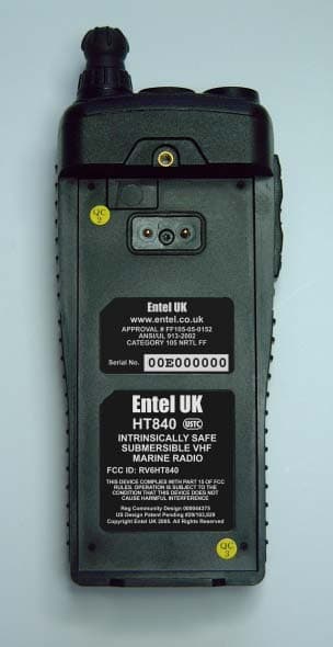
RV6HT840
Mar 02, 2006Hand held marine radio
Equipment Class
TNF - Licensed Non-Broadcast Transmitter Held to Face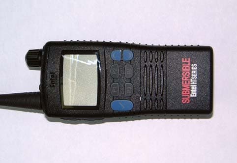
RV6HT880
Nov 04, 2005FM Handheld Submersible Transceiver HT880
Equipment Class
TNF - Licensed Non-Broadcast Transmitter Held to Face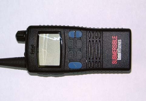
RV6HT780
Sep 08, 2005FM Handheld Submersible Transceiver HT780
Equipment Class
TNF - Licensed Non-Broadcast Transmitter Held to Face