RW3RFS1RFS USB Transceiver
Bron Elektronik AG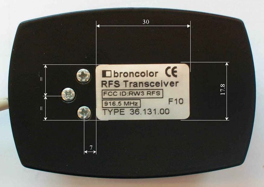
Click to zoom
Application Details
- Equipment Class
- DXX - Part 15 Low Power Communication Device Transmitter
- Date of Grant
- Jun 06, 2004
- Application Purpose
- Original Equipment
- Date of Application
- Jun 06, 2004
- Equipment Note
- RFS USB Transceiver
- Frequency Range
- 916.50000000 - 916.50000000
- Company
- Bron Elektronik AG
- Country
- Switzerland
Documents & Files
Document Text
Text extracted from the exhibit documents filed with the FCC. Open a document above to read the original.
Users Manual
Annex No.5 User Manual Functional Description Radio System for Studio Flash Equipment 916.5MHz: RFS USB Transceiver L7254.01 914.0MHz: RFS USB Transceiver L7254.03 Bron Elektronik AG, 4123 Allschwil, Switzerland The application concerns the data transmission from an operator console (MAC/PC) to the flash units of a Photo Studio, in both directions, as well as the transmission of a flash trigger signal from the camera to all of the flash units. The RFS USB transceiver is plugged in the PC/MAC. The power supply is supplied from USB Hup. RFS USB Transceiver specifications ( typical ): • Output power: 12dBm • Frequency: 914.0-916.5MHz • Modulation: ASK • Data rate / Data format: 38.4 kBaud Æ 76.8kBit in Manchester • Transmission time flash triggering: 0.625ms – 0.833ms • Transmission time data-block: 1.9ms – 10.4ms • Size: 80mm x 55mm x 30mm • Operating voltage / current: RF 3V / 2mA • Operating voltage / current: USB: 5V / 25mA • Operating current USB Suspend: 100μA • RF input impedance 50 ohms • Antenna: Helical SMA • USB specification: USB 2.0 • LED: Communication indicator • Switches: „test“ transmit flash block „+“ and „-„ transmit data block • Sync connector: transmit flash block Transmission format Data format: MSB first Flash-block: • Preamble 11100110 01100110 optimisation of DC-balance • Start symbol „Flash“: 01110001 11010110 Manchester modified • ID (Studio no.) 01010101 01010110 Æ ID=1 ( Manchester ) Data-block: • Preamble: 11100110 01100110 optimisation of DC-balance • Start symbol „Data“: 01110001 11011001 Manchester modified • Block number: ... each new block receives a new block number, but not a repetition. • Byte count: ... • Start info: 01011010 01011001 • Studio ID: 01010101 01010110 Æ ID=1 ( Manchester ) • Unit ID: ... • n data ... ... ... ... max. 50 Byte • Check sum: ... • End Symbol „Data“: 01110110 00100110 Manchester modified A dual directional data transmission only takes place when the setting on the flash units or the operator console (MAC/PC) is adjusted. This reduces the probability of a collision with a flash- block. A correctly transmitted data-block is confirmed with an ACK. An unconfirmed data-block is repeated. A flash-block is not repeated. 106-108 Anglesey Business Park, Littleworth Road, Hednesford, Staffs. WS12 5NR. U.K. Tel: +44 1543 878343 Fax: +44 1543 871714 E-mail: [email protected] Visit our web page : www.mobilemark.com Specifications subject to change without notice. (9/2001) MOBILE MARKMOBILE MARK COMMUNICATIONS ANTENNAS R 1/4 wave Device Antennas Quarterwave antennas provide performance for products with the minimum of size. Full length quarterwave design provide the maximum efficiency, while loaded helical stub antennas provide minimum size. The full length models use a flexible whip, whereas the helical antenna use a hard radome. Overall performance of quarterwave antennas does depend on the ground plane provided by the radio system or the mounting configuration. Quarterwave antennas are broadband compared to other designs and can effectively be used in most apllications. For OEM applications, performance can often be maximized with a one time factory adjustment. Connector styles available are TNC, SMA, MMCX or a thread ferrule assembly. The thread ferrule provides the most economical solution, but does require a special mechanical configuration for mounting and feeding the RF signal. Special connectors are also available, please consult factory. Models with "-925 designators also overlap the ISM 902- 928 band and are now in lieu of the "-915" models. Model Numbers - Straight Antennas Model Frequency Style Connector PSTG0-900MM 824-894MHz Full 1/4 10-32 PSTG0-900MX 824-894MHz Helical 4mm x .5 PSTG0-900HS 824-894MHz Helical SMA PSTG0-900SE 824-894MHz Full 1/4 SMA PSTG0-900TE 824-894MHz Full 1/4 TNC PSTG0-925MM 870-960MHz Full 1/4 10-32 PSTG0-925MX 870-960MHz Helical 4mm x .5 PSTG0-925HS 870-960MHz Helical SMA PSTG0-925SE 870-960MHz Full 1/4 SMA PSTG0-925TE 870-960MHz Full 1/4 TNC Model Numbers - Right Angle Antennas Model Frequency Style Connector MDM-900OP 824-894MHz Full 1/4 MMCX MDM-925OP 870-960MHz Full 1/4 MMCX Frequency Guide -900 Models For US Cellular (Analog & Digital), CDPD -925 Models For EU Cellular, ISM, Mobitex and Skytel Special configurations available upon request. Please consult factory for details/availability. Specifications Frequency: Gain: Bandwidth @ 2:1 SWR: Impedance: Maximum Power: Connector: See above 0dBi max for ¼ wave See frequency range above 50 ohm nominal 10 watts See above, special connectors also available, please consult factory for details. Whip Length: ¼ wave ¼ wave, helical Whip Material ¼ wave ¼ wave, helical 95mm (3.75") maximum, varies slightly based on frequency. 32mm (1.25") maximum Rubber jacket/flexible cable ABS radome, helical radiator Models for Cellular, CDPD, ISM, GSM, Mobitex and Skytel applications Quarterwave styles in flexible whip, helical stubs with hard radome Sleek profile, with a variety of connector styles Customization available for OEM applications For 800 & 900 MHz Applications Helical stub models with various connectors Full 1/4 models in straight and right angle R Operating instructions b r o n c o l o r Radio Frequency System (RFS) Before use We are very pleased you have chosen a broncolor Radio Frequency System RFS unit which is a high-quality product in every respect. If used properly, it will render you many years of good service. Please read the information contained in these operating instructions carefully. They contain important details on the use, safety and maintenance of the appliance. Keep these operating instructions in a safe place and pass them on to further users if necessary. With the broncolor Radio Frequency System you can trigger, and operate by remote control broncolor units which are equipped with an integrated RFS interface. The RFS units should be used only for professional shooting and should be operated exclusively by trained staff. 1.…
Text truncated - open the document above for the full version.
Block Diagram
Annex No.7 Page 1 of 1 Block Diagram : Oscillator frequencies generated or used in the device: : 6.000MHz / : 8.000MHz
Cover Letter(s)
m. dudde hochfrequenz-technik Rottland 5a, D-51429 Bergisch-Gladbach DIN EN ISO/IEC 17025 zertifiziert Akkreditiertes Testhaus - Reg.-Nr.: TTI-P-G128/96 Tel. : +49 22 07 - 96 89 - 0 Fax : +49 22 07 - 96 89 - 20 email: [email protected] www.dudde.com Federal Communications Commission 7435 Oakland Mills Road Columbia, MD 21046 Gentlemen: This letter is to comply with Section 0.457(d)(2)(i) pertaining to confidential material. Bron Elektronik AG, Hagmattstrasse 7, CH-4123 Allschwil / Switzerland would like the following documents regarding this submission for FCC ID: RW3RFS1 to be kept confidential. Transceiver, RFS USB Transceiver L7254.XX 1. Page 2 to 7 Annex no. 8 document “Schematics” The above material contains trade secret or technical data, which would customarily be guarded from competitors. We do not want these documents to be accessible to the general public. Sincerely, m. dudde hochfrequenz-technik Manfred Dudde
External Photos
Annex No.1 Page 1 of 2 External Photographs of the Equipment Under Test EXTERNAL FRONT VIEW PHOTO Annex No.1 Page 2 of 2 EXTERNAL REAR VIEW PHOTO
ID Label/Location Info
Annex No.4 Page 1 of 2 FCC ID LABEL SAMPLE SKETCH OF FCC ID LABLE LOCATION Annex No.4 Page 2 of 2
Internal Photos
Annex No.2 Page 1 of 2 Internal Photographs of the Equipment Under Test INTERNAL UPPER SIDE PHOTO Annex No.2 Page 2 of 2 INTERNAL LOWER SIDE PHOTO
Operational Description
Annex No.5 Technical Description Radio System for Studio Flash Equipment 916.5MHz: RFS USB Transceiver L7254.01 914.0MHz: RFS USB Transceiver L7254.03 Bron Elektronik AG, 4123 Allschwil, Switzerland The application concerns the data transmission from an operator console (MAC/PC) to the flash units of a Photo Studio, in both directions, as well as the transmission of a flash trigger signal from the camera to all of the flash units. The RFS USB transceiver is plugged in the PC/MAC. The power supply is supplied from USB Hup. RFS USB Transceiver specifications ( typical ): • Output power: 12dBm • Frequency: 914.0-916.5MHz • Modulation: ASK • Data rate / Data format: 38.4 kBaud Æ 76.8kBit in Manchester • Transmission time flash triggering: 0.625ms – 0.833ms • Transmission time data-block: 1.9ms – 10.4ms • Size: 80mm x 55mm x 30mm • Operating voltage / current: RF 3V / 2mA • Operating voltage / current: USB: 5V / 25mA • Operating current USB Suspend: 100μA • RF input impedance 50 ohms • Antenna: Helical SMA • USB specification: USB 2.0 • LED: Communication indicator • Switches: „test“ transmit flash block „+“ and „-„ transmit data block • Sync connector: transmit flash block Transmission format Data format: MSB first Flash-block: • Preamble 11100110 01100110 optimisation of DC-balance • Start symbol „Flash“: 01110001 11010110 Manchester modified • ID (Studio no.) 01010101 01010110 Æ ID=1 ( Manchester ) Data-block: • Preamble: 11100110 01100110 optimisation of DC-balance • Start symbol „Data“: 01110001 11011001 Manchester modified • Block number: ... each new block receives a new block number, but not a repetition. • Byte count: ... • Start info: 01011010 01011001 • Studio ID: 01010101 01010110 Æ ID=1 ( Manchester ) • Unit ID: ... • n data ... ... ... ... max. 50 Byte • Check sum: ... • End Symbol „Data“: 01110110 00100110 Manchester modified A dual directional data transmission only takes place when the setting on the flash units or the operator console (MAC/PC) is adjusted. This reduces the probability of a collision with a flash- block. A correctly transmitted data-block is confirmed with an ACK. An unconfirmed data-block is repeated. A flash-block is not repeated. 106-108 Anglesey Business Park, Littleworth Road, Hednesford, Staffs. WS12 5NR. U.K. Tel: +44 1543 878343 Fax: +44 1543 871714 E-mail: [email protected] Visit our web page : www.mobilemark.com Specifications subject to change without notice. (9/2001) MOBILE MARKMOBILE MARK COMMUNICATIONS ANTENNAS R 1/4 wave Device Antennas Quarterwave antennas provide performance for products with the minimum of size. Full length quarterwave design provide the maximum efficiency, while loaded helical stub antennas provide minimum size. The full length models use a flexible whip, whereas the helical antenna use a hard radome. Overall performance of quarterwave antennas does depend on the ground plane provided by the radio system or the mounting configuration. Quarterwave antennas are broadband compared to other designs and can effectively be used in most apllications. For OEM applications, performance can often be maximized with a one time factory adjustment. Connector styles available are TNC, SMA, MMCX or a thread ferrule assembly. The thread ferrule provides the most economical solution, but does require a special mechanical configuration for mounting and feeding the RF signal. Special connectors are also available, please consult factory. Models with "-925 designators also overlap the ISM 902- 928 band and are now in lieu of the "-915" models. Model Numbers - Straight Antennas Model Frequency Style Connector PSTG0-900MM 824-894MHz Full 1/4 10-32 PSTG0-900MX 824-894MHz Helical 4mm x .5 PSTG0-900HS 824-894MHz Helical SMA PSTG0-900SE 824-894MHz Full 1/4 SMA PSTG0-900TE 824-894MHz Full 1/4 TNC PSTG0-925MM 870-960MHz Full 1/4 10-32 PSTG0-925MX 870-960MHz Helical 4mm x .5 PSTG0-925HS 870-960MHz Helical SMA PSTG0-925SE 870-960MHz Full 1/4 SMA PSTG0-925TE 870-960MHz Full 1/4 TNC Model Numbers - Right Angle Antennas Model Frequency Style Connector MDM-900OP 824-894MHz Full 1/4 MMCX MDM-925OP 870-960MHz Full 1/4 MMCX Frequency Guide -900 Models For US Cellular (Analog & Digital), CDPD -925 Models For EU Cellular, ISM, Mobitex and Skytel Special configurations available upon request. Please consult factory for details/availability. Specifications Frequency: Gain: Bandwidth @ 2:1 SWR: Impedance: Maximum Power: Connector: See above 0dBi max for ¼ wave See frequency range above 50 ohm nominal 10 watts See above, special connectors also available, please consult factory for details. Whip Length: ¼ wave ¼ wave, helical Whip Material ¼ wave ¼ wave, helical 95mm (3.75") maximum, varies slightly based on frequency. 32mm (1.25") maximum Rubber jacket/flexible cable ABS radome, helical radiator Models for Cellular, CDPD, ISM, GSM, Mobitex and Skytel applications Quarterwave styles in flexible whip, helical stubs with hard radome Sleek profile, with a variety of connector styles Customization available for OEM applications For 800 & 900 MHz Applications Helical stub models with various connectors Full 1/4 models in straight and right angle R
Test Report
Test Report : 04001927 Page 1 of 25 EUT : RFS USB Transceiver L7254.01 RFS USB Transceiver L7254.03 FCC ID: RW3RFS1 Issue date: 2004-03-29 m. dudde hochfrequenz-technik Rottland 5a Vers. Datum:2002-12 D-51429 Bergisch Gladbach Tel. +49 2207-9689-0 Fax +49 2207 9689-20 e-mail: [email protected] http://www.dudde.com TTI-P-G 128/96 Test Report acc. to the relevant standard: 47 CFR Part 15 C – Intentional Radiators Measurement Procedure: ANSI C63.4 - 1992 relating to Bron Elektronik AG RFS USB Transceiver Variants: L7254.01 / L7254.03 Measurement of Radio- Noise Emissions from Low- Voltage Electrical and Electronic Equipment Technical characteristics and test methods for radio equipment in the frequency range 9 kHz to 40 GHz Test Report : 04001927 Page 2 of 25 EUT : RFS USB Transceiver L7254.01 RFS USB Transceiver L7254.03 FCC ID: RW3RFS1 Issue date: 2004-03-29 m. dudde hochfrequenz-technik Rottland 5a Vers. Datum:2002-12 D-51429 Bergisch Gladbach Tel. +49 2207-9689-0 Fax +49 2207 9689-20 e-mail: [email protected] http://www.dudde.com Manufacturers Details Manufacturer Bron Elektronik AG Manufacturers Grantee Code RW3 Hagmattstrasse 7 CH-4123 Allschwil Switzerland Phone : 0041/614 85 85 Fax : 0041/614 8585 Manufacturers Address E- Mail:[email protected] 47 CFR Part 15C - Intentional Radiators Relevant Standard Used ANSI C63.4-1992 Test Report prepared by Ralf Trepper m.dudde hochfrequenz-technik (Labor) Rottland 5a D-51429 Bergisch Gladbach Germany Phone: +49 2207 96890 Fax : +49 2207 968920 Technical engineer E-mail: [email protected] Equipment Under Test (EUT) Equipment Category Transceiver Trade Name Type designation RFS USB Transceiver L7254.XX Serial No. None / Sample No.1(916.5MHz), Sample No.3(914.0MHz) L7254.01 (916.5MHz) L7254.03 (914.0MHz) Variants Test Report : 04001927 Page 3 of 25 EUT : RFS USB Transceiver L7254.01 RFS USB Transceiver L7254.03 FCC ID: RW3RFS1 Issue date: 2004-03-29 m. dudde hochfrequenz-technik Rottland 5a Vers. Datum:2002-12 D-51429 Bergisch Gladbach Tel. +49 2207-9689-0 Fax +49 2207 9689-20 e-mail: [email protected] http://www.dudde.com 0 Test result CFR Section Report Chapter Requirements headline Test result OK 15.203 10.1 Antenna Requirement pass fail n.a. 15.249 (a) 10.2 Field Strength Limits (Fundamental) pass fail n.a. 15.249(d) 15.209 10.2 Radiated Spurious Emissions pass fail n.a. 15.207 10.3 Conducted Emissions pass fail n.a. 15.215 (c) 10.4 20 dB Bandwidth pass fail n.a. Test requirements kept yes no . Signature Test Personnel ........................................ Ralf Trepper . Signature of the Company Official ......................................... Manfried Dudde Test Report : 04001927 Page 4 of 25 EUT : RFS USB Transceiver L7254.01 RFS USB Transceiver L7254.03 FCC ID: RW3RFS1 Issue date: 2004-03-29 m. dudde hochfrequenz-technik Rottland 5a Vers. Datum:2002-12 D-51429 Bergisch Gladbach Tel. +49 2207-9689-0 Fax +49 2207 9689-20 e-mail: [email protected] http://www.dudde.com List of contents Page 0 Test result............................................................................................................................................. 3 1 Testing laboratory................................................................................................................................5 2 Introduction......................................................................................................................................... 5 3 Product................................................................................................................................................. 6 4 Test schedule........................................................................................................................................ 6 5 Product and Measurement documentation......................................................................................... 7 6 Observations and comments................................................................................................................ 7 7 Summary.............................................................................................................................................. 7 8 Conclusions......................................................................................................................................... 8 9 Operation Description......................................................................................................................... 9 10.1 Antenna Requirement..................................................................................................................... 10 10.1.1 Regulation ...................................................................................................................................... 10 10.1.2 Result ............................................................................................................................................. 10 10.2 Radiated emissions......................................................................................................................... 11 10.2.1 Regulation ...................................................................................................................................... 11 10.2.2 Test equipment ............................................................................................................................... 13 10.2.2 Test procedures............................................................................................................................... 13 10.2.3 Calculation of field strengths limits ................................................................................................ 14 10.2.4 Calculation of average correction factor.......................................................................................... 14 10.2.5 Calculation of the field strengths .......................................................................…
Text truncated - open the document above for the full version.
Test Report
Annex No.3 Page 1 of 1 OCCUPIED BANDWITH PLOT
Test Setup Photos
Annex No.6 Page 1 of 1 Test Setup Photos :
Contact Information
Applicant
Joerg Roth(CTO)
Technical Contact
m.dudde high frequency technologyRalf Trepper
[email protected]+49 2207 9689 0
Rottland 5A · Bergisch Gladbach · Germany
Test Firm
m. dudde hochfrequenz-technikManfred Dudde
Technical Specifications
| # | Rule Parts | Frequency Range | Power Output |
|---|---|---|---|
| 2 | 15C | 916.5 MHz - 916.5 MHz | - |
Other Applications from Bron Elektronik AG
RW3RFS24
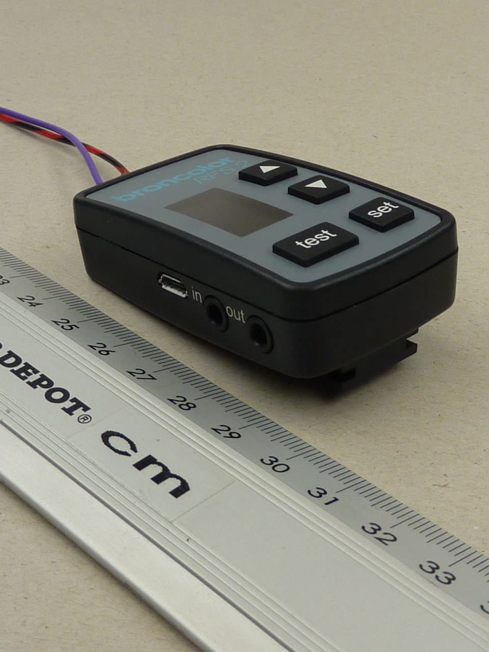
Feb 02, 2012Remote Control for Flashlights
Equipment Class
DXX - Part 15 Low Power Communication Device Transmitter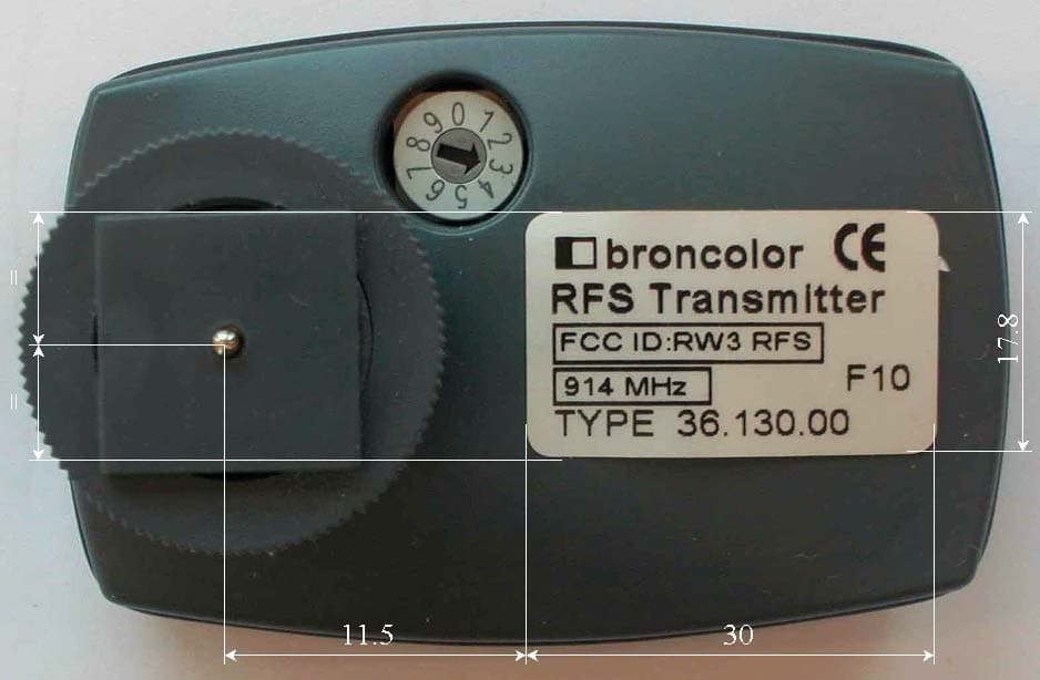
RW3RFS3
Jun 08, 2004RFS Transmitter
Equipment Class
DXX - Part 15 Low Power Communication Device Transmitter
RW3RFS2
Jun 06, 2004RFS Transceiver Module
Equipment Class
DXX - Part 15 Low Power Communication Device Transmitter