RW3RFS24Remote Control for Flashlights
Bron Elektronik AG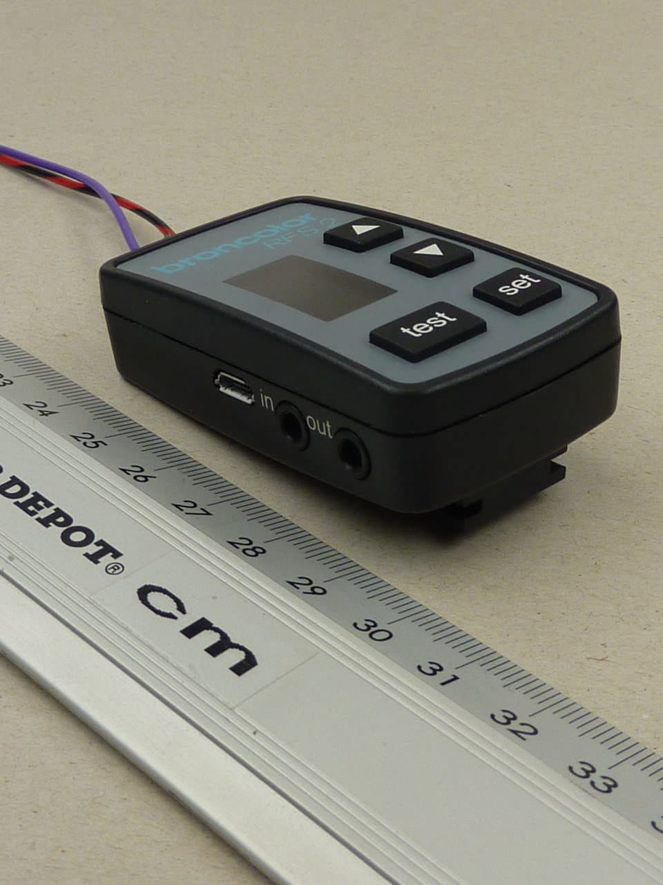
Click to zoom
Application Details
- Equipment Class
- DXX - Part 15 Low Power Communication Device Transmitter
- Date of Grant
- Feb 02, 2012
- Application Purpose
- Original Equipment
- Date of Application
- Feb 02, 2012
- Equipment Note
- Remote Control for Flashlights
- Frequency Range
- 2403.00000000 - 2481.00000000
- Company
- Bron Elektronik AG
- Country
- Switzerland
Documents & Files
Document Text
Text extracted from the exhibit documents filed with the FCC. Open a document above to read the original.
Users Manual
RFS2 Operating instructions | Bedienungsanleitung | Mode d‘emploi 2 1 case 2 lithium buttoncell li-Mn cr2450 (560 mah,3 V) 3 display 4 uSB socket 5 Sync in 6 Sync out 3 4 5 678 9 10 11 12 1 2 7 "test"key 8 Base plate (only withreceiver kit) 9 "set"key (to set frequency andstudio channel) 10 Keys " ", "" (to regulate the flash energy andfor adjustment of the frequency andstudio address) 11 Sync cable for flash unit minito mini (only withreceiver kit) 12 Sync cable for camera scOpe OF delivery 3 13 15 16 14 13 rechargeable battery packfor receiver operation (incl. rechargable batteries) 14 Power supply device (only withreceiver kit) 15 chargecable (for use incar) (only withreceiver kit) 16 uSBcable (only withreceiver kit) 4 BrOncOlOr radiO Frequency SySteM 2 Before use We are very pleasedyou have chosen a broncolorradio FrequencySystem rFS 2 unit, which is a high-quality product inevery respect. if used properly, it willrender you manyyears of good service. Pleaseread the information contained in these operating instructionscarefully. they contain important details on the use, safety and maintenance of the device.Keep these opera- ting instructions in a safe place and pass them onto further users if neces- sary. they are also available online at www.broncolor.com. With the broncolor rFS 2you can trigger and operate byremotecontrol broncolor units, which are equipped with an integrated rFS 2 interface. 5 1. OperatiOn as transmitter Or receiver the transceivercan be operated in two modes. the unit is always in trans- mitting mode when used in battery operation. the transceiver functions as transmitter. if the transceiver is supplied with energy through the provided power supply unit via the uSB-port, the device switchesover automaticallyto receiving mode. the transceiver functions asreceiver. Manual switchover of the mode is not possible. 6 2. radiO Frequency system2 (rFs2) the radio frequencysystem broncolor rFS 2consists of thefollowing ele- ments: > rFS 2 as transmitter on thecamera > rFS 2 asreceiver at the power packs / monolights without internal rFS 2 radio frequencysystem > rFS 2 as internalradio frequencysystem integrated in the power packs / monolights 2.1 rFs 2 transceiver as transmitter the rFS2 transceiver is usedto remote-control one or morebroncolor power packs or monolights equipped with rFS 2 interface usingradio signalsto trigger flashes.Power packs or monolights without integrated rFS 2 inter- face s can be operated byconnecting an rFS 2 transceiver (asreceiver) to them (see 1.2). 7 to enable severa l rFS 2 devicesto communicate with each other, they must all be set at the samestudio address. rFS 2 devices with the samestudio addresscan be simultaneouslyremote controlled. thus, thanksto the vari- ous studio addresses, severa l rFS 2 groups of unitscan be independently remote controlled without interfering with each other. Flash triggering issynchronized either via thecentral contact of the hot shoe or thesync jack of thecamera. Outdoors, theremote control range is upto 50 m; indoors, it is upto 30 m. the transceiver is powered by a lithium button cell (li-Mn cr2450).to minimise energyconsumption, the transceiver is set to an energy-saving mode afterfour hours have elapsed. if a flash triggering action occurs through thecamera whilst the rFS 2 transceiver is in energy- saving mode, a slight delay of thesynchronization with thecamera shutter release can take place. the rFS 2 transceiver quits the energy-saving mode after this flashrelease. attention: although thisradio system allowsthe selection of upto 99 studio addresses, the number of actually available channels depends on thecon- nected rFs 2 flash unit. For detailed instructions, pleaseconsult the manual of therespective flash unit. 8 2.2 rFs 2 transceiver asreceiver the devicecan be used as anexternal receiver for broncolor power packs, monolights, and third-party units that are not equippedto receive rFS 2 data. When using the device as areceiver, use therespective power supply unit and plug it into the uSB socket on the side of the device. the device will automatically switchto the receiver mode. connect thesync cable with the "out" jack of the rFS 2 transceiver and the sync jack on the flash unit. 2.3 Operation > Keys the device hasfour keys: "test", "set", " " and "". depending on the current mode of the device, they have different functions. the functions depend on how long thekeys are pressed. > Key press duration a shortkey press is shorter than a second, alonger actuation islonger than a second. > trigger test flash / activatesync outconnection to trigger atest flash, briefly press the "test" button on the rFS 2 transcei- ver. Pressing the “test” button also activates thesync outconnection. 9 3. set studiO address the transceiver must have the samestudio address as the flash units or receivers that areto be used. to set thestudio address, please proceed asfollows: 1.) Press and hold the "set"key until "St" blinks on the display and the studio number is indicated. 2.) Set thestudio address withkeys " " and "". 3.) Save the settings by pressing and holding the "set"key. "St" is now displayed continuously. 10 4. set Frequency channel Manyradio frequency devices transmit in the same frequency band as the rFS 2 transceiver.to minimize mutual interference, the rFS 2 transceiver provides a choice of 40 different frequency channels. the transceiver must be setto the same frequency channel as the flash units that areto be used. the receiver units on the samestudio address will automaticallysynchronize frequencies when the frequency of the transmitter is changed. procedure: > Switch on all flash units orreceivers that areto be used. > Set all these flash unitsto the samestudio address as that of the rFS 2 transceiver. > Make sure the rFS 2 transceiver and the flash units that areto be synchro- nised are as closetogether as possible. tip:For the synchronization process, the units should have intervisibility with the…
Text truncated - open the document above for the full version.
External Photos
ANNEX C:EXTERNAL PHOTOS OF THE EUT Test engineer: Thomas KÜHNTest Report No.:F120019E1 Date of issue:20 January 2012Order No.:12-120019page1 of2 120019_a.JPG:RFS 2, 3 -D view 1 ANNEX C:EXTERNAL PHOTOS OF THE EUT Test engineer: Thomas KÜHNTest Report No.:F120019E1 Date of issue:20 January 2012Order No.:12-120019page2 of2 120019_b.JPG:RFS 2, 3 -D view 2
ID Label/Location Info
ID Labble Locatioon Info
Internal Photos
ANNEX B:INTERNAL PHOTOS OF THE EUT Test engineer: Thomas KÜHNTest Report No.:F120019E1 Date of issue:20 January 2012Order No.:12-120019page1 of4 120019_c.JPG:RFS 2, internal view 1 ANNEX B:INTERNAL PHOTOS OF THE EUT Test engineer: Thomas KÜHNTest Report No.:F120019E1 Date of issue:20 January 2012Order No.:12-120019page2 of4 120019_d.JPG:RFS 2, internal view 2 ANNEX B:INTERNAL PHOTOS OF THE EUT Test engineer: Thomas KÜHNTest Report No.:F120019E1 Date of issue:20 January 2012Order No.:12-120019page3 of4 120019_e.JPG:RFS 2, PCB, top view ANNEX B:INTERNAL PHOTOS OF THE EUT Test engineer: Thomas KÜHNTest Report No.:F120019E1 Date of issue:20 January 2012Order No.:12-120019page4 of4 120019_f.JPG:RFS 2, PCB, bottom view
Test Report
ANNEX DRESULTS OF THE RECEIVER MEASUREMENTS Test engineer:Thomas KÜHNReport Number:F120019E1 Date of issue:20 January 2012Order Number:12-120019page1 of 8 1RADIATED EMISSIONS (RECEIVER) 1.1Preliminary radiated emission measurement Ambienttemperature20 °CRelative humidity32 % Position of EUT:The EUT was set-up on a non-conducting table of a height of 0.8 m. The distance between EUT and antenna was 3 m. Cable guide:For detail information of test set-up and the cable guide refer to the pictures in annex A of this test report. Test record:Allresults are shown in the following. Supply voltage:During all measurements the EUT was supplied by the external battery, which was charged by an external AC/DC adaptor typeNK120P100PGS,which was supplied by 120 V AC / 60 Hz. Remark:As pre-tests have shown, the emissions of the EUT are not depending on the receiver operation mode. Therefore all measurements were carried out in operationo mode 5. 120019_18.wmf: Receiver emissions from 30 MHz to 230 MHz (operation mode 5): A UnitdBμV/m P20 TDF Start30MHzStop230MHz20MHz/ RefLvl 70dB* RefLvl 70dB* RBW100kHz VBW100kHz SWT110ms RFAtt0dB IN1 1MA1MAX1MA -20 -10 0 10 20 30 40 50 60 -30 70 TEST EQUIPMENT USED FOR THE TEST: 29, 31– 36, 43,44, 49 ANNEX DRESULTS OF THE RECEIVER MEASUREMENTS Test engineer:Thomas KÜHNReport Number:F120019E1 Date of issue:20 January 2012Order Number:12-120019page2 of 8 120019_19.wmf: Receiver emissions from 230 MHz to 1 GHz (operation mode 5): A UnitdBμV/m 1MAX1MA P20 TDF Start230MHzStop1GHz77MHz/ RefLvl 70dB* RefLvl 70dB* RFAtt0dBRBW100kHz VBW100kHz SWT195ms 1MA IN1 -20 -10 0 10 20 30 40 50 60 -30 70 The following frequencies were found during the preliminary emission measurement: 45.725 MHz, 75.480 MHz and 99.171 MHz. These frequencies have to be measured in a final measurement on a open are test site. The results were presented in the following. 120019_20.wmf: Receiver emissions from1 GHz to 4 GHz (operation mode 5): 1MAX A 1MA UnitdBμV P20 Start1GHzStop4GHz300MHz/ RefLvl 70dBμV RefLvl 70dBμV RBW100kHz VBW100kHz SWT760ms RFAtt0dB 1MA IN1 -20 -10 0 10 20 30 40 50 60 -30 70 ANNEX DRESULTS OF THE RECEIVER MEASUREMENTS Test engineer:Thomas KÜHNReport Number:F120019E1 Date of issue:20 January 2012Order Number:12-120019page3 of 8 120019_21.wmf: Receiver emissions from4 GHz to 12.5 GHz (operation mode 5): UnitdBμV 1MAX A 1MA Start4GHzStop12.5GHz850MHz/ RefLvl 70dBμV RefLvl 70dBμV RBW100kHz VBW100kHz SWT2.15s RFAtt0dB 1MA IN1 -20 -10 0 10 20 30 40 50 60 -30 70 The following frequency was found during the preliminary emission measurement: 2.792 GHz. This frequency has to be measured in a final measurement. The results were presented in the following. ANNEX DRESULTS OF THE RECEIVER MEASUREMENTS Test engineer:Thomas KÜHNReport Number:F120019E1 Date of issue:20 January 2012Order Number:12-120019page4 of 8 1.2Final radiated emission measurement (30 MHz to 1 GHz) Ambient temperature20 °CRelative humidity35 % Position of EUT:The EUT was set-up on a non-conducting table of a height of 0.8 m. The distance between EUT and antenna was 3 m. Cable guide:For detail information of test set-up and the cable guide refer to the pictures in annex A of this test report. Test record:Allresults are shown in the following. Supply voltage:During all measurements the EUT was supplied by the external battery, which was charged by an external AC/DC adaptor typeNK120P100PGS,which was supplied by 120 V AC / 60 Hz. Test results:The test results were calculated with the following formula: Result [dBμV/m] = reading [dBμV] + cable loss [dB] + antenna factor [dB/m] The measured points and the limit line in the following diagram refer to the standard measurement of the emitted interference in compliance with the above-mentioned standard. The measured points marked with an x arethe measured results of the standard final measurement on the open area test site. 0 10 20 30 40 50 60 70 80 Level [dBμV/m] 30M40M50M70M100M200M300M400M600M1G Frequency [Hz] xx x x xMES 120019ff1_fin QP LIM FCC p15.109 F B QP Data record name: 120019ff1 (Position 1) ANNEX DRESULTS OF THE RECEIVER MEASUREMENTS Test engineer:Thomas KÜHNReport Number:F120019E1 Date of issue:20 January 2012Order Number:12-120019page5 of 8 0 10 20 30 40 50 60 70 80 Level [dBμV/m] 30M40M50M70M100M200M300M400M600M1G Frequency [Hz] x x x x xMES 120019ff2_fin QP LIM FCC p15.109 F B QP Data record name: 120019ff2 (Position 2) The results of the standard subsequent measurement on the open area test site are indicated in the table below. The limits as well as the measured results (levels) refer to the above mentioned standard while taking account of the specified requirements for a 3 m measuring distance. Themeasurement time with the quasi-peak measuring detector is 1 second. Result measured with the quasipeak detector: (This value is marked in the diagrams by an x) Spurious emissions outside restricted bands Frequency MHz Result dBμV/m Limit dBμV/m Margin dB Readings dBμV Antenna factor dB/m Cable loss dB Height cm Azimuth deg Pol.Pos. 45.72529.040.011.016.511.80.7105.044.0Vert.2 75.48028.840.011.220.57.40.9400.060.0Hor.1 99.17136.343.57.224.510.71.1355.0315.0Hor.1 Measurement uncertainty+2.2 dB /-3.6 dB Test:Passed TEST EQUIPMENT USED FOR THE TEST: 14– 20 ANNEX DRESULTS OF THE RECEIVER MEASUREMENTS Test engineer:Thomas KÜHNReport Number:F120019E1 Date of issue:20 January 2012Order Number:12-120019page6 of 8 1.3Final radiated emission measurement (1 GHz to 12.5 GHz) Ambient temperature20 °CRelative humidity32 % Position of EUT:The EUT was set-up on a non-conducting table of a height of 0.8 m. The distance between EUT and antenna was 3 m. Cable guide:For detail information of test set-up and the cable guide refer to the pictures in annex A of this test report. Test record:Allresults are shownin the following. Supply voltage:During all measurements the EUT was supplied by the external battery, which was charged by an external AC/DC adaptor typeNK120P100PGS,which was supplied by 120 V…
Text truncated - open the document above for the full version.
Test Report
Königswinkel 10 32825 Blomberg Germany Phone:+49 (0) 52 35 95 00-0 Fax:+49 (0) 52 35 95 00-10 Test Report Report Number: F120019E1 Applicant: Bron Elektronik AG Manufacturer: Bron Elektronik AG Equipment under Test (EUT): RFS 2 Laboratory (CAB) accredited by Deutsche Gesellschaft für Akkreditierung mbH in compliance with DIN EN ISO/IEC 17025 under the Reg. No. DGA-PL-105/99-22, FCC Test site registration number 90877 Test engineer:Thomas KÜHNReport Number:F120019E1 Date of issue:20 January 2012Order Number:12-120019page2 of32 REFERENCES [1]ANSI C63.4-2009American National Standard for Methods of Measuring of Radio-Noise Emissions from Low-Voltage Electrical and ElectronicEquipment in the Range of 9 kHz to 40 GHz. [2]FCC CFR 47 Part 15 (August 2011)Radio Frequency Devices TEST RESULT The requirements of the tests performed as shown in the overview (clause 4) werefulfilled by the equipment under test. The complete test results are presented in the following. RESERVATION T h i s t e s t r e p o r t i s o n l y v a l i d i n i ts o r i g i n a l f o r m . Any reproduction of its contents in extracts without written permission of the accredited test laboratory PHOENIX TESTLAB GmbH is prohibited. The test results herein refer only to the tested sample. PHOENIX TESTLAB GmbH is not responsible for any generalisations or conclusions drawn from these test results concerning further samples. Any modification of the tested samples is prohibited and leads to the invalidity of this test report. Each page necessarily contains the PHOENIX TESTLAB Logo and the TEST REPORT NUMBER. Test engineer: Thomas KÜHN20 January 2012 NameSignatureDate Authorized reviewer: Bernd STEINER20 January 2012 Name Signature Date Test engineer:Thomas KÜHNReport Number:F120019E1 Date of issue:20 January 2012Order Number:12-120019page3 of32 Contents:Page 1IDENTIFICATION.......................................................................................................................4 1.1Applicant.............................................................................................................................4 1.2Manufacturer.......................................................................................................................4 1.3Test laboratory....................................................................................................................4 1.4EUT (Equipment Under Test)..............................................................................................5 1.5Technical data of equipment................................................................................................5 1.6Dates................................................................................................................................... 6 2OPERATIONAL STATES...........................................................................................................6 3ADDITIONAL INFORMATION....................................................................................................7 4OVERVIEW................................................................................................................................7 5TEST RESULTS.........................................................................................................................8 5.120dB bandwidth..................................................................................................................8 5.1.1Method of measurement (20 dB bandwidth).................................................................. 8 5.1.2Test results (20 dB bandwidth)......................................................................................9 5.2Band-edge compliance......................................................................................................11 5.2.1Method of measurement (band-edge compliance (radiated))......................................11 5.2.2Test result (band-edge compliance (radiated))............................................................12 5.3Radiated emissions...........................................................................................................14 5.3.1Method of measurement (radiated emissions).............................................................14 5.3.2Test results (radiated emissions).................................................................................19 5. 3.2.1Preliminary emission measurement (1 MHz to 25 GHz)........................................19 5.3.2.2Final radiated emission measurement (1 GHz to 25 GHz)....................................27 6TEST EQUIPMENT AND ANCILLARIES USED FOR TESTS..................................................30 7REPORT HISTORY..................................................................................................................32 8LIST OF ANNEXES..................................................................................................................32 Test engineer:Thomas KÜHNReport Number:F120019E1 Date of issue:20 January 2012Order Number:12-120019page4 of32 1IDENTIFICATION 1.1Applicant Name:Bron Elektronik AG Address: Hagmattstrasse 7 CH– 4123 Allschwil Country:Switzerland Name for contact purposes:Mr. Mario BORER Phone:+41 61 485 85 85 Fax:+41 61 485 85 00 eMail Address:[email protected] Applicant represented during the test by the following person: - 1.2Manufacturer Name:BronElektronik AG Address: Hagmattstrasse 7 CH– 4123 Allschwil Country:Switzerland Name for contact purposes:Mr. Mario BORER Phone:+41 61 485 85 85 Fax:+41 61 485 85 00 eMail Address:[email protected] Manufacturer represented during the test by the following person: - 1.3Test laboratory The tests were carried outat:PHOENIX TESTLAB GmbH Königswinkel 10 32825 Blomberg Germany accredited byDGA Deutsche Gesellschaft für Akkreditierung mbHin compliance with DIN EN ISO/IEC 17025 under Reg. No.DGA-PL-105/99-22,FCC Test site registration number 90877andIndustry Canada Test site registration IC3469A-1. Test engineer:Thomas K…
Text truncated - open the document above for the full version.
Test Setup Photos
ANNEX A: TEST SET-UP PHOTOS Test engineer: Thomas KÜHNTest Report No.:F120019E1 Date of issue:20 January 2012Order No.:12-120019page1 of8 120019_3.JPG:RFS 2 transmitter, test set-up fully anechoic chamber (Pos. 1) ANNEX A: TEST SET-UP PHOTOS Test engineer: Thomas KÜHNTest Report No.:F120019E1 Date of issue:20 January 2012Order No.:12-120019page2 of8 120019_2.JPG:RFS 2 transmitter, test set-up fully anechoic chamber (Pos. 2) ANNEX A: TEST SET-UP PHOTOS Test engineer: Thomas KÜHNTest Report No.:F120019E1 Date of issue:20 January 2012Order No.:12-120019page3 of8 120019_10.JPG:RFS 2 receiver, test set-up fully anechoic chamber (Pos. 1) ANNEX A: TEST SET-UP PHOTOS Test engineer: Thomas KÜHNTest Report No.:F120019E1 Date of issue:20 January 2012Order No.:12-120019page4 of8 120019_13.JPG:RFS 2 receiver, test set-up fully anechoic chamber (Pos. 2) ANNEX A: TEST SET-UP PHOTOS Test engineer: Thomas KÜHNTest Report No.:F120019E1 Date of issue:20 January 2012Order No.:12-120019page5 of8 120019_6.JPG:RFS 2 transmitter, test set-up fully anechoic chamber ANNEX A: TEST SET-UP PHOTOS Test engineer: Thomas KÜHNTest Report No.:F120019E1 Date of issue:20 January 2012Order No.:12-120019page6 of8 120019_5.JPG:RFS 2 transmitter, test set-up fully anechoic chamber ANNEX A: TEST SET-UP PHOTOS Test engineer: Thomas KÜHNTest Report No.:F120019E1 Date of issue:20 January 2012Order No.:12-120019page7 of8 120019_1.JPG:RFS 2 transmitter, testset-up fully anechoic chamber ANNEX A: TEST SET-UP PHOTOS Test engineer: Thomas KÜHNTest Report No.:F120019E1 Date of issue:20 January 2012Order No.:12-120019page8 of8 120019_16.JPG:RFS 2 receiver, test set-up shielded room
Contact Information
Applicant
Joerg Roth(CTO)
Test Firm
IMST GmbHJohannes Borkes
Technical Specifications
| # | Rule Parts | Frequency Range | Power Output |
|---|---|---|---|
| 1 | 15C | 2.40 GHz - 2.48 GHz | - |
Other Applications from Bron Elektronik AG
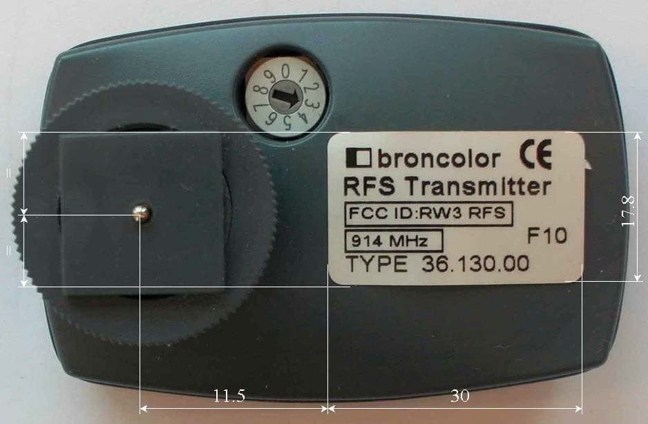
RW3RFS3
Jun 08, 2004RFS Transmitter
Equipment Class
DXX - Part 15 Low Power Communication Device Transmitter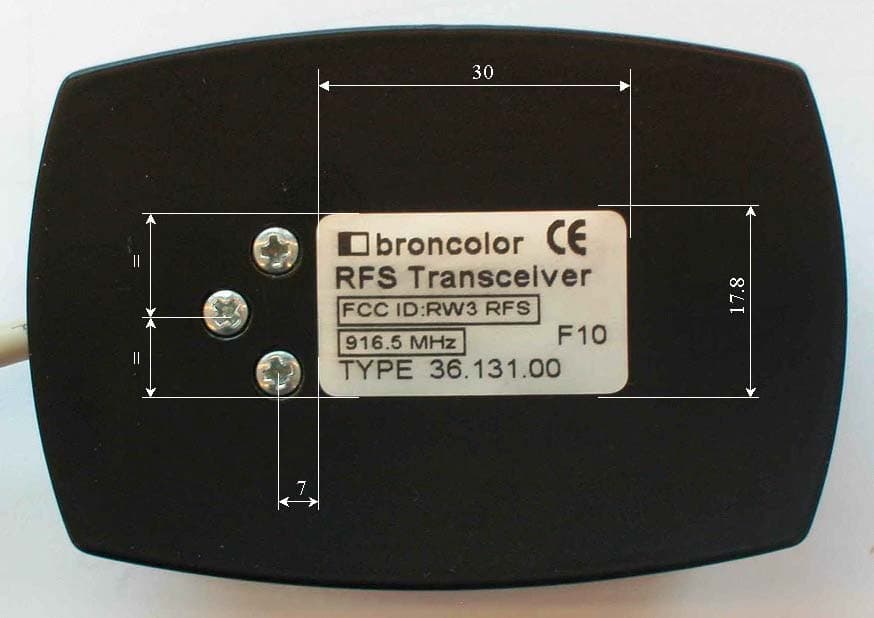
RW3RFS1
Jun 06, 2004RFS USB Transceiver
Equipment Class
DXX - Part 15 Low Power Communication Device Transmitter
RW3RFS2
Jun 06, 2004RFS Transceiver Module
Equipment Class
DXX - Part 15 Low Power Communication Device Transmitter