RWT-ER89Bluetooth Headset
Etymotic Research, Inc.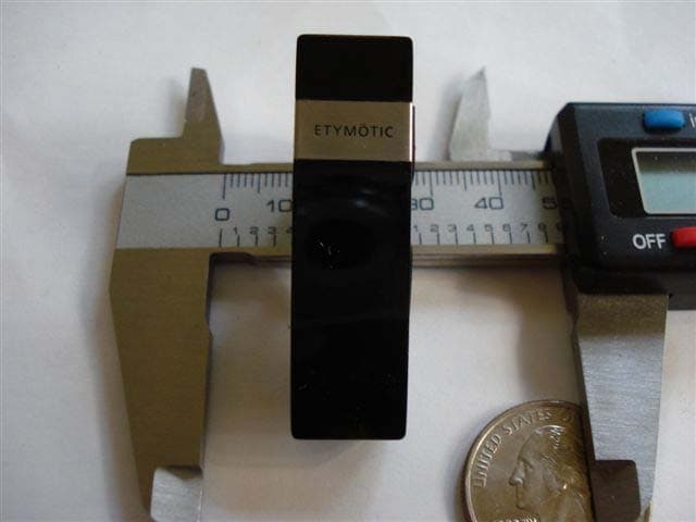
Click to zoom
Application Details
- Equipment Class
- DSS - Part 15 Spread Spectrum Transmitter
- Date of Grant
- Dec 21, 2007
- Application Purpose
- Original Equipment
- Date of Application
- Dec 21, 2007
- Equipment Note
- Bluetooth Headset
- Frequency Range
- 2402.00000000 - 2480.00000000
- Company
- Etymotic Research, Inc.
- Country
- United States
Documents & Files
Document Text
Text extracted from the exhibit documents filed with the FCC. Open a document above to read the original.
Users Manual
User Manual Bluetooth Headset etyBLU Detachable Boom Mic Introduction The Etymotic etyBlu™ headset contains two microphones. One microphone is located at the end of the earpiece; the other, a highly-directional, noise-rejecting microphone is located at the tip of the boom. The combination of an in-ear noise-isolating earphone and a directional microphone placed close to the mouth provides exceptional sound quality and clear communication at both ends of the conversation. The etyBlu headset was developed by Etymotic Research for use in high levels of background noise. The boom is detachable. Another Etymotic first. The etyBlu headset utilizes Bluetooth® 2.0 + EDR extended data rate wireless technology. Features •etyBlu Bluetooth® headset •Detachable directional microphone boom •Highest isolation and noise rejection of any headset— with boom mic in place •Optional adjustable earloop that can be worn on either ear •5-6 hours talk time; 70 hours standby •Lightweight (< .5 oz) •Charges from USB port (cable included) •etyBlu Bluetooth headset •Earloop •Detachable Boom mic •Leather storage case •Assorted eartips •Filter changing tool with replacement filters •USB charging cable Included Identification D C A E B A. Earloop B. Volume C. Microphone D. Multifunction Button E.Detachable Boom Mic F. Eartip/ Speaker F C Side view— no boom, no earhook B D Getting Started Before using the etyBlu headset: •Fully charge the headset. Typical charging time from empty is 2-3 hours; 80% charge in 1 hour •Pair the headset with a Bluetooth-enabled device, e.g., cell phone, PDA, computer When properly inserted, the headset is self-supporting in the ear canal. An optional earloop is supplied with the headset. The earloop can be used on either ear. Sound quality and noise isolation depend on a good eartip seal. Selecting an Eartip Insertion •Carefully insert the earpiece while pulling up and out on the back of the ear. •Twist the earpiece while inserting until outside noise is blocked out. •Position the earpiece for best fit and comfort. • Flanged eartip:Moistening eases insertion. • Foam eartip:Roll down or compress foam eartip before inserting. Hold the eartip in place for about 5 seconds while the foam expands to create a tight seal in the ear canal. For a video on proper earphone insertion go to www.etymotic.com. Removal To avoid discomfort, remove the headset slowly with a twisting motion to gradually break the seal. Open jaw slightly to equalize pressure, because suction can occur when the eartip is removed. Wearing the EtyBlu Important:To insure optimal performance it is important that the eartip seals the ear canal. •Choose an eartip that fits. •Push the earloop through the earloop hole and adjust it to fit comfortably on the ear. The earpiece is designed to be self-supporting in the ear canal, so the earhook is optional. •When using the boom, there is only one way to attach it to the headset. Bend the gooseneck so that the tip of the microphone is close to the mouth. •The etyBlu headset can be worn on either ear. Boom Mic—When to use Without Boom Mic For quiet /low noise environments. With Boom Mic For noisy environments. - Gives up to 25 dB more noise rejection than microphones that are not close to the mouth, which can mean a critical difference in understanding and being understood. Boom Mic— Connect Connect The plug on the boom is designed to connect to the headset only one way. 1. Gently snap the connector into the socket. 2. Do not force the plug into the socket; it should insert easily. 3.When the boom is connected correctly,the opening at the tip of the microphone is closest to the mouth and the opening at the middle of the mic tip is facing away from the mouth. Boom Mic—Disconnect Disconnect 1. Hold the boom where it connects to the headset and gently pull downward. 2. Keep the boom in the storage case for easy access. LED Chart Power ONBlue and yellow LEDs are solid for 3 seconds while turning on Power OFFBlue and yellow LEDs are solid for 3 seconds while turning off then all LEDs off Pairing ModeBlue blinking Active callBlue LED blinks once per second No active callBlue LED blinks every 3 seconds ChargingSolid yellow LED Low batteryBlinking yellow LED Charge completeYellowLED off Battery Life The etyBlu comes with an integrated lithium polymer (rechargeable) battery. Charge the headset for at least one hour before first use. Battery life External BT device with EDR support> 5 hours External BT device with basic rate support4 hours Standby time70 hours Low Battery Indicator The software monitors the battery voltage level. When there is less than five minutes of use left, the LED blinks yellow. Charging Typical charging time From empty: 2-3 hours 80% charge: 1 hour Charging with the USB connecter (included) •Plug the charging cable into a computer USB port. •Plug the boom connector into the etyBlu headset as shown; it should slide in easily. •The solid yellow LED will indicate that the headset is charging. •When charging is complete the yellow LED turns OFF. Charging with a wall charger (not included) •Plug the charger adapter into an AC wall outlet. •Plug the USB end of the etyBlu charging cable into the adapter. •Plug the boom connector on the etyBlu charging cable into the headset as shown; it should slide in easily. •The solid yellow LED will indicate that the headset is charging. •When charging is complete the yellow LED turns OFF. Pairing Pairing varies by device The headset is discoverable for five minutes after Power On. •Turn the phone OFF and then back ON. •Turn on the mobile phone’s Bluetooth function. •Press and hold the Multifunction Button (MFB) for 5 seconds. •The blue LED will flash rapidly when ready for pairing. The etyBlu stays in pairing mode for 5 minutes. •Activate the search for BT and/or audio devices on the phone •When the etyBlu is found, the phone will display “ER89 etyBlu.” Scroll to it and press OK to confirm pairing. •If a passkey is requested, enter 0000. Note:Bluet…
Text truncated - open the document above for the full version.
Cover Letter(s)
1 Etymotic Research, Inc. 61 Martin Lane Elk Grove Village, IL 60007 USA Federal Communication Commission Equipment Authorization Division, Application Processing Branch 7435 Oakland Mills Road Columbia, MD 21048 December 6, 2007 Subject: Short-Term Confidentiality Request for FCC ID: RWT-ER89 Pursuant to Paragraphs §0.457 and §0.459 of the Commission's Rules (47 C.F.R.) and to avoid the premature release of sensitive information prior to marketing or release of the product to the public, Etymotic Research requests the following documents contained in this certification application be temporarily withheld from public disclosure for an initial period of 45 days: FCC ID Number Product Title/Model RWT-ER89 etyBlu Bluetooth Isolator Headset M/N ER-89 1) External Photos 2) Internal Photos 3) Test Setup Photos 4) User’s Manual Etymotic Research also acknowledges that they will provide appropriate notice to ATCB should either of the following occur: 1) if the applicant requires additional 45 day extension periods they will notify ATCB with a new request letter at least 7 days prior to the short-term confidentiality expiration date, or 2) immediately notify ATCB in the event the information regarding the product or the product is made available to the public. ATCB will then release the documents listed above for public disclosure pursuant to FCC Public Notice DA 04-1705. Sincerely,
Cover Letter(s)
1 Etymotic Research, Inc. 61 Martin Lane Elk Grove Village, IL 60007 USA Federal Communication Commission Equipment Authorization Division, Application Processing Branch 7435 Oakland Mills Road Columbia, MD 21048 December 6, 2007 Subject: Permanent Confidentiality Request for FCC ID: RWT-ER89 Pursuant to Paragraphs §0.457, §0.459 and §0.475(d) of the Commission's Rules (47 C.F.R.) and Section §552(b)(4) of the Freedom of Information Act, Etymotic Research requests permanent confidentiality for the following products: FCC ID Number Product Title/Model RWT-ER89 etyBlu Bluetooth Isolator Headset M/N ER-89 We request that the following information be held permanently confidential: 1) Electrical Schematics & Layout of the Circuitry 2) Bill of Materials 3) Operational Description 4) Block Diagram No other items submitted as part of the equipment authorization filing process are deemed confidential. The above exhibits contain Etymotic Research’s trade secrets and proprietary information. The public disclosure of this information could harm Etymotic Research and be of benefit to our competitors by revealing trade secret and proprietary information about the design of our product. This material is not customarily available to the general public and we request that it be withheld from public inspection. If you have any questions, please feel free to contact me at the address shown below. Sincerely,
Cover Letter(s)
Response to ATCB Comments FCC ID: RWT-ER89 1 Washington Laboratories, Ltd. 7560 LINDBERGH DRIVE GAITHERSBURG, MD 20879 (301) 417 – 0220 FAX # (301) 417 - 9069 December 19, 2007 Mr. Rich Fabina American Telecommunications Certification Body Inc. 6731 Whittier Ave McLean, VA 22101 RE: Comments of December 5, 2007 APPLICATION: R W T-ER89 & IC: 6648A-ER89 for Etymotic Research, Inc. Dear Mr. Fabina: Below are the comments that you have provided regarding the application for certification referenced above. Our responses to those comments are in bold italic. Many responses refer you to additional exhibit(s) which has been uploaded to the application folder at the ATCB website. Thank you for your attention. Please feel free to contact us for any additional information that you may require. Regards, Steven D. Koster EMC Operations Manager Brian J. Dettling Documentation Specialist WLL Project: 10120 1) There are multiple problems with the letter requesting confidentiality of exhibits submitted to the FCC. (a) Short term confidentiality is usually requested in a separate letter for 45 days at a time with a maximum of 180 days total, with extensions. Please see the attached for a detailed description of the process. (b) Specific exhibits are requested to be held short term confidential for a 45 day period rather than the whole application. Again please refer to the attached for an explanation. (c) Permanent confidentiality of the schematic diagram and layout of the circuitry cannot be granted because there is no exhibit of the layout of the circuitry. Response to ATCB Comments FCC ID: RWT-ER89 2 After reading the attached, please revise the letter requesting standard (permanent) confidentiality and submit a separate letter requesting short term confidentiality that specifies the exhibits and the length of the request. R. The above items have been addressed in the following documents: “RWT-ER89 - Request for Short- Term Confidentiality – 071207” & “RWT-ER89 - Request for Standard Confidentiality – 071207”. 2) Please provide a letter from Etymotic Research, Inc that gives TEM Consulting the authority to sign the letter of agency for Etymotic Research. The submitted agency letter is signed by a TEM Consulting employee who has no authority to act on behalf of Etymotic Research. R. Please see “RWT-ER89 - Authorization from Entymotic” 3) Please provide a letter requesting confidentiality of exhibits for Industry Canada (IC). All exhibits are submitted to IC because of changes to their system in September of 2007. Therefore to protect release of confidential information from IC, submission of a letter to IC requesting confidentiality is recommended. Please see the IC application form on the ATCB website for an example letter. R. Please see “IC - Request for Confidentiality - 6648A-ER89 - 071207” 4) Please submit a test setup photos exhibit. No test setup photos were provided for this device as specified by the FCC. R. Please see “RWT-ER89 Test Setup Photo” 5) Please provide new internal photos of the subject device. The submitted photos are too dark to clearly show the component location on the printed circuit board. R. Please see “RWT-ER89 - Internal Photos 12.07” 6) Please address RF safety in accordance with Section 15.247(i) of the FCC Rules. No RF safety evaluation was provided for the FCC. R. Please see “RWT-ER89 RF Exposure Info” 7) Please confirm that this transmitter was tested with and without the boom microphone to evaluate worst case emissions from it. Also declare which configuration represents worst case for this accessory. R. The data presented in the report is the worst case data. The unit was evaluated with and without the boom microphone and the ear loop. 8) Please describe what material the ear loop is made of. If any metal is incorporated into the ear loop, it should also be included in worst case emissions evaluation and disclosure of worst case configuration. R. The ear loop is all metal. The loop was installed with the boom and the emissions were investigated. The worst case emissions are the emissions that are in the report. 9) In the test report, the fifth column in the radiated emission test results above 1 GHz on pages 50 of 59 to 57 of 59 indicate that the detector function was set to Quasi-peak but the notes column at the end indicates peak and average detectors were used. Please submit a corrected test report to indicate which one is correct. R. Report has been corrected to reflect QP was not used. Response to ATCB Comments FCC ID: RWT-ER89 3 10) The submitted IC application form is not completed at the end. The gain of antenna, type of modulation, emission designator and transmitter spurious headings on the submitted form are blank. Please submit a completed form. R. Please see “6648A-ER89 Application Form revised”
Cover Letter(s)
American Telecommunications Certification Body Inc. 6731 Whittier Ave, McLean, VA 22101 January 7, 2008 TO: FCC FROM: American TCB RE: FCC ID: RWT-ER89, Request for supercede of External Photos Please remove originally uploaded external photos and replace with rev ext photos uploaded January 5, 2008. The reason for the request is due to the newer ext photos having more clarity. Thank you Marianne Bosley American TCB Inc. Direct – 717-676-3203
External Photos
External Photos FCC ID: RWT-ER89 Description: Bluetooth Isolator Headset Model Name: etyBlu Model Number: ER-89 Etymotic Research 61 Martin Ln. Elk Grove Village, IL 60007 By TEM Consulting, LP 140 River Rd. Georgetown, TX 78628 December 2007 Top View Side View
RF Exposure Info
Document 10120-MPE FCC ID: RWT-ER89 RF Exposure Test Report Washington Laboratories, Ltd December 2007 Maximum Permissible Exposure Evaluation for Entymotic Research etyBlu FCC ID: RWT-ER89 December 2007 Prepared by: Brian Dettling Reviewed by: Steve Koster WLL PROJECT #: 10120 This report may not be reproduced, except in full, without the prior written consent of Washington Laboratories, Ltd. ` RF Exposure Evaluation Document 10120-MPE FCC ID: RWT-ER89 RF Exposure Test Report Washington Laboratories, Ltd December 2007 1 Maximum Permissible Exposure Test Report for FCC ID: RWT-ER89 1.0 Introduction This report has been prepared on behalf of Entymotic Research etyBlu. Transmitter to show compliance with the RF exposure requirements as defined in FCC §1.1307. 1.1 Requirements Three different categories of transmitters are defined by the FCC in OET Bulletin 65. These categories are fixed installation, mobile, and portable and are defined as follows: Fixed Installations: fixed location means that the device, including its antenna, is physically secured at a permanent location and is not able to be easily moved to another location. Additionally, distance to humans from the antenna is maintained to at least 2 meters. Mobile Devices: a mobile device is defined as a transmitting device designed to be used in other than fixed locations and to be generally used in such a way that a separation distance of at least 20 centimeters is normally maintained between the transmitter's radiating structures and the body of the user or nearby persons. Transmitters designed to be used by consumers or workers that can be easily re-located, such as a wireless modem operating in a laptop computer, are considered mobile devices if they meet the 20 centimeter separation requirement. The FCC rules for evaluating mobile devices for RF compliance are found in 47 CFR §2.1091. Portable Devices: a portable device is defined as a transmitting device designed to be used so that the radiating structure(s) of the device is/are within 20 centimeters of the body of the user. Portable device requirements are found in Section 2.1093 of the FCC's Rules (47 CFR§2.1093). For this test report the Entymotic Research etyBlu Antenna: Internal Evaluation distance: 20cm test distance. The FCC also categorizes the use of the device as based upon the user’s awareness and ability to exercise control over his or her exposure. The two categories defined are Occupational/ Document 10120-MPE FCC ID: RWT-ER89 RF Exposure Test Report Washington Laboratories, Ltd December 2007 2 Controlled Exposure and General Population/Uncontrolled Exposure. These two categories are defined as follows: Occupational/Controlled Exposure: In general, occupational/controlled exposure limits are applicable to situations in which persons are exposed as a consequence of their employment, who have been made fully aware of the potential for exposure and can exercise control over their exposure. This exposure category is also applicable when the exposure is of a transient nature due to incidental passage through a location where the exposure levels may be higher than the general population/uncontrolled limits, but the exposed person is fully aware of the potential for exposure and can exercise control over his or her exposure by leaving the area or by some other appropriate means. Awareness of the potential for RF exposure in a workplace or similar environment can be provided through specific training as part of a RF safety program. If appropriate, warning signs and labels can also be used to establish such awareness by providing prominent information on the risk of potential exposure and instructions on methods to minimize such exposure risks. General Population/Uncontrolled Exposure: The general population / uncontrolled exposure limits are applicable to situations in which the general public may be exposed or in which persons who are exposed as a consequence of their employment may not be made fully aware of the potential for exposure or cannot exercise control over their exposure. Members of the general public would come under this category when exposure is not employment-related; for example, in the case of a wireless transmitter that exposes persons in its vicinity. Warning labels placed on low-power consumer devices such as cellular telephones are not considered sufficient to allow the device to be considered under the occupational/controlled category, and the general population/uncontrolled exposure limits apply to these devices. Since there are no warnings or training associated with this unit and it can be used by anyone, the Entymotic Research etyBlu is evaluated to the General Population/Uncontrolled Exposure limits. 1.2 Radio Frequency Radiation Exposure Evaluation The highest RF output power of the unit was measured is recorded. According to §1.1310 of the FCC rules, the power density limit for General Population/Uncontrolled Exposure is 1mW/cm 2 . The MPE shall be calculated at 20cm to show compliance with the power density limit. The following formula was used to calculate the Power Density: 2 4R PG S π = Document 10120-MPE FCC ID: RWT-ER89 RF Exposure Test Report Washington Laboratories, Ltd December 2007 3 Where: S = Power Density P = Output Power at the Antenna Terminals G = Gain of Transmit Antenna (linear gain-isotropic) R = Distance from Transmitting Antenna Table 1. Transmitter MPE Calculation Summary One Transmitter Frequency2400MHz Limit1.000mW/cm^2 Distance (cm), R =20cm Power (dBm), P = 4.43dBm TX Ant Gain (dBi), G =2.6dB Power Density: 0.00mW/cm^2 Separation<20 cm Minimum Distance:0.6 cm
RF Exposure Info
Antenna Gain FCC ID: RWT-ER89 Description: Bluet ooth Isolator Headset Model Name: ety Blu Model Number: ER-89 Etymotic Research 61 Martin Ln. Elk Grove Village, IL 60007 By TEM Consulting, LP 140 River Rd. Georgetown, TX 78628 November 2007 The peak measured antenna gain is 2.62 dBi. Antenna Analysis Proprietary Document Timothy Milam 6451 FM-1105, Georgetown, TX 78626 Page #: 1 of 1 Tel: (512) 638-2643 Fax: (512) 532-0947
Test Report
FCC & IC Certification Test Report For the Etymotic Research, Inc. ER89 Bluetooth Headset FCC ID: RWT-ER89 IC ID: 6648A-ER89 WLL JOB# 10120/10121 November 30, 2007 Prepared for: Etymotic Research, Inc. 61 Martin Lane Elk Grove Village, IL 60007 Prepared By: Washington Laboratories, Ltd. 7560 Lindbergh Drive Gaithersburg, Maryland 20879 Etymotic Research, Inc. ER89 Bluetooth Earphones FCC & IC Certification Test Report November 2007 FCC & IC Certification Test Report for the Etymotic Research, Inc. ER89 Bluetooth Headset FCC ID: RWT-ER89 IC ID: 6648A-ER89 Novemeber 30, 2007 W L L JOB# 10120/10121 Prepared by: Steve Dovell Compliance Engineer Reviewed by: Steven D. Koster EMC Operations Manager Etymotic Research, Inc. ER89 Bluetooth Headset FCC & IC Certification Test Report November 2007 WLL Report #10120 - ii - © 2007 Washington Laboratories, Ltd. Abstract This report has been prepared on behalf of Etymotic Research, Inc. to support the attached Application for Equipment Authorization. The test report and application are submitted for a Frequency Hopping Spread Spectrum Transmitter under Part 15.247 of the FCC Rules and Regulations and Spectrum Management and Telecommunications Policy RSS-210 of Industry Canada. This Certification Test Report documents the test configuration and test results for an Etymotic Research, Inc. ER89 Bluetooth Headset. Testing was performed on an Open Area Test Site (OATS) of Washington Laboratories, Ltd, 7560 Lindbergh Drive, Gaithersburg, MD 20879. Site description and site attenuation data have been placed on file with the FCC's Sampling and Measurements Branch at the FCC laboratory in Columbia, MD. The Industry Canada OATS numbers are 3035A-1 and 3035A-2 for Washington Laboratories, Ltd. Site 1 and Site 2, respectively. Washington Laboratories, Ltd. has been accepted by the FCC and approved by the American Association for Laboratory Accreditation (A2LA) under Certificate 2675.01. as an independent FCC test laboratory. The Etymotic Research, Inc. ER89 Bluetooth Headset complies with the limits for a Frequency Hopping Spread Spectrum Transmitter device under FCC Part 15.247 and Industry Canada RSS- 210. Etymotic Research, Inc. ER89 Bluetooth Headset FCC & IC Certification Test Report November 2007 WLL Report #10120 - iii - © 2007 Washington Laboratories, Ltd. Table of Contents Abstract ........................................................................................................................................... ii 1 Introduction ..........................................................................................................................1 1.1 Compliance Statement .....................................................................................................1 1.2 Test Scope ........................................................................................................................1 1.3 Contract Information ........................................................................................................1 1.4 Test Dates ........................................................................................................................1 1.5 Test and Support Personnel .............................................................................................1 2 Equipment Under Test .........................................................................................................2 2.1 EUT Identification & Description ...................................................................................2 2.2 Test Configuration ...........................................................................................................2 2.3 Support Equipment ..........................................................................................................3 2.4 Testing Algorithm ............................................................................................................3 2.5 Test Location ...................................................................................................................3 2.6 Measurements ..................................................................................................................3 2.6.1 References ....................................................................................................................3 2.7 Measurement Uncertainty ................................................................................................3 3 Test Equipment ....................................................................................................................5 4 Test Results ..........................................................................................................................6 4.1 Dwell Time ......................................................................................................................6 4.2 RF Power Output: (FCC Part §2.1046) ...........................................................................7 4.3 Occupied Bandwidth: (FCC Part §2.1049) ....................................................................10 4.4 RF Peak Power Spectral Density (§15.247(e) and RSS-210, Annex 8.2) .....................14 4.5 Channel Spacing and Number of Hop Channels (FCC Part §15247(a)(1) ....................18 4.6 Conducted Spurious Emissions at Antenna Terminals (FCC Part §2.1051) .................24 4.7 Radiated Spurious Emissions: (FCC Part §2.1053) .......................................................47 4.7.1 Test Procedure .........................................................................................................47 4.8 AC Powerline Conducted Emissions: (FCC Part §15.207 and RSS-GEN) ...................58 List of Tables Table 1. Device Summary ............................................................................................................... 2 Table 2: Test Equipment List ...............................................................................................…
Text truncated - open the document above for the full version.
Test Setup Photos
Test Setup Photos ©2007 Washington Laboratories, Ltd Test Setup Photos ©2007 Washington Laboratories, Ltd Test Setup Photos ©2007 Washington Laboratories, Ltd Test Setup Photos ©2007 Washington Laboratories, Ltd Test Setup Photos ©2007 Washington Laboratories, Ltd Test Setup Photos ©2007 Washington Laboratories, Ltd Test Setup Photos ©2007 Washington Laboratories, Ltd
Contact Information
Applicant
Susan Reid(Director of Quality Assurance & Regulatory Affairs)
Technical Contact
Washington Laboratories, Ltd.Steven D. Koster
[email protected]301-216-1500
7560 Lindbergh Drive · Gaithersburg · United States
Non-Technical Contact
Washington Laboratories, Ltd.Brian J. Dettling
[email protected]301-216-1500
Test Firm
Washington Laboratories, Ltd.John Repella
Technical Specifications
| # | Rule Parts | Frequency Range | Power Output |
|---|---|---|---|
| 1 | 15C | 2.40 GHz - 2.48 GHz | 2.77 mW |
Other Applications from Etymotic Research, Inc.
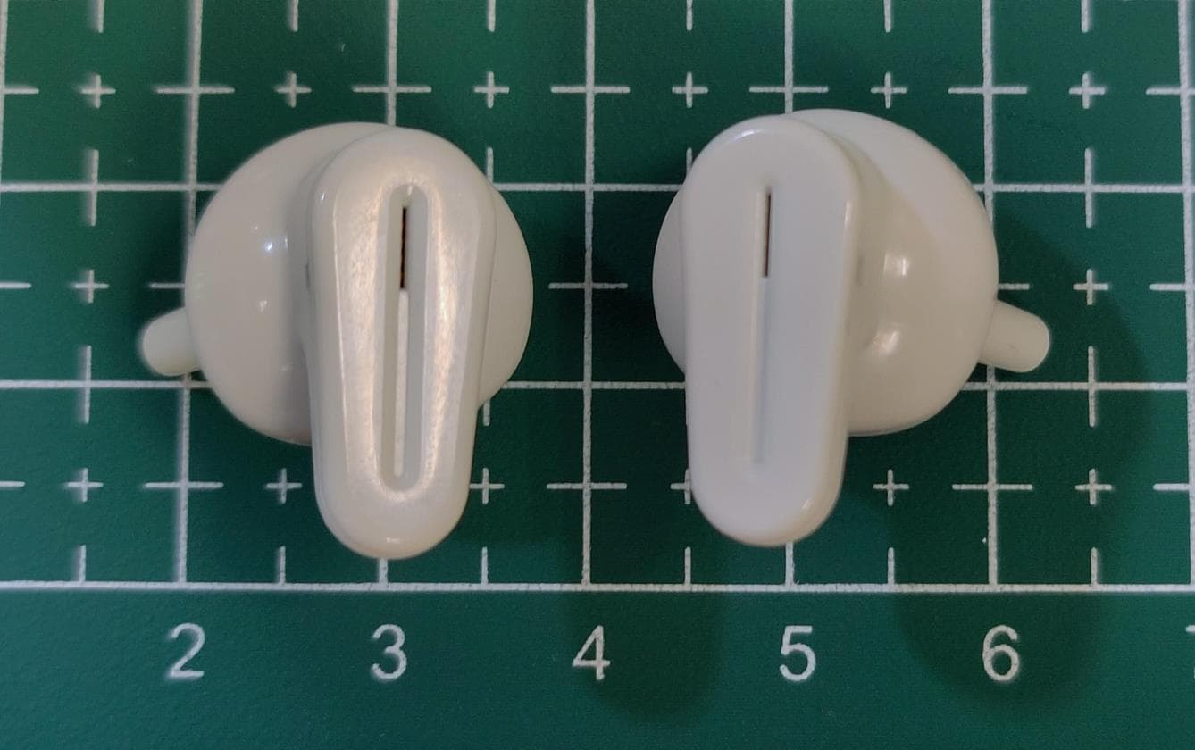
RWT-BAVOTW
Jul 04, 2023Hearing Aid with Bluetooth Connectivity
Equipment Class
DTS - Digital Transmission System
RWT-ER200
Jan 13, 2021Etymotion BT Bluetooth Cable
Equipment Class
DSS - Part 15 Spread Spectrum Transmitter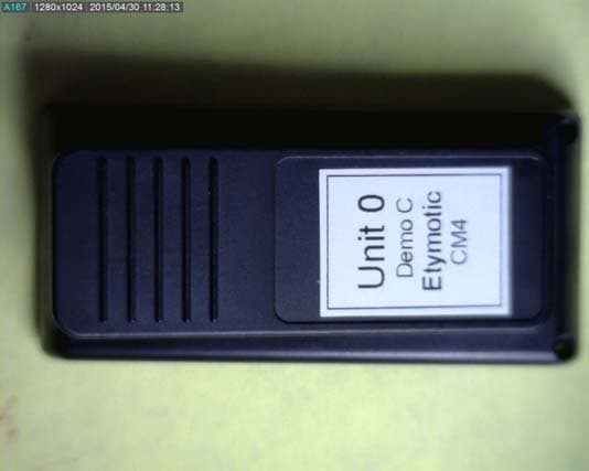
RWT-ER84
Nov 15, 2015Companion Mic - CM4
Equipment Class
DTS - Digital Transmission System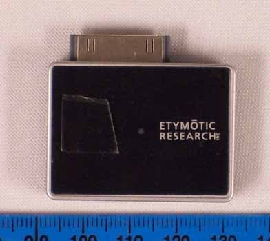
RWT-ER88I
Sep 26, 2006iPod Dongle
Equipment Class
DSS - Part 15 Spread Spectrum Transmitter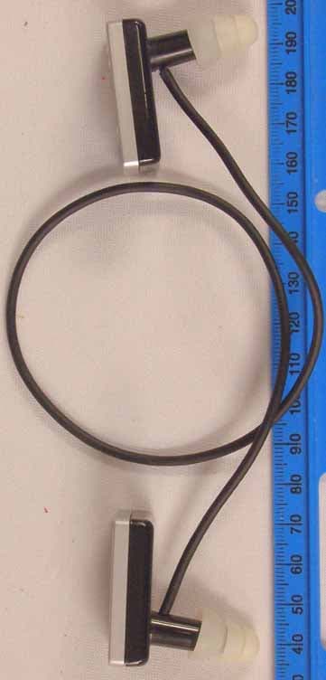
RWT-ER88
Sep 24, 2006Bluetooth Headset
Equipment Class
DSS - Part 15 Spread Spectrum Transmitter