RX2TBTBMF30B0Telematic Control Unit
Marelli Europe S.p.A.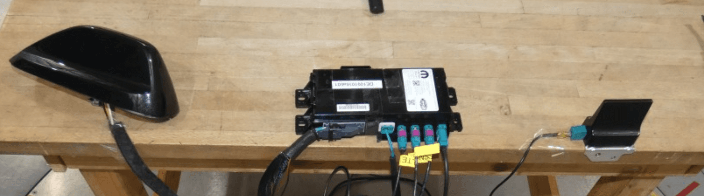
Click to zoom
Application Details
- Equipment Class
- DTS - Digital Transmission System
- Date of Grant
- Dec 21, 2020
- Application Purpose
- Original Equipment
- Date of Application
- Dec 21, 2020
- Equipment Note
- Telematic Control Unit
- Frequency Range
- 2412.00000000 - 2462.00000000
- Company
- Marelli Europe S.p.A.
- Country
- Italy
Documents & Files
Document Text
Text extracted from the exhibit documents filed with the FCC. Open a document above to read the original.
Users Manual
TBM2 – Telematic Box Module 1 INTRODUCTION ASSIST AND SOS SYSTEM The TBM2 module (Model name: TBTBMF30B0) is a Telematic Box Module, providing the following services: - Assist and SOS System, giving access to Assistance or Emergency call functions to FCA US LLC Assistance Service Network - Wi-Fi access point 1 — SOS Button 2 — ASSIST Button Assist And SOS Buttons The overhead console contains an ASSIST and a SOS button, used to access to the Assist and Emergency call functions of TBM2. . 2 TBM2 WARNING! ALWAYS obey traffic laws and pay attention to the road. ALWAYS drive safely with your hands on the steering wheel. You have full responsibility and assume all risks related to the use of the features and applications in this vehicle. Only use the features and applications when it is safe to do so. Failure to do so may result in an accident involving serious injury or death. NOTE: • Your vehicle may be transmitting data as authorized by the subscriber. • The SOS and ASSIST buttons will only function if you are connected to an operable LTE (voice/data) or 4G (data) network. Other Uconnect services will only be operable if your SiriusXM Guardian™ service is active and you are connected to an operable LTE (voice/data) or 4G (data) network. ASSIST Call The ASSIST Button is used to automatically connect you to any one of the following support centers: • Roadside Assistance – If you get a flat tire, or need a tow, just push the ASSIST button and you’ll be connected to someone who can help. Roadside Assistance will know what vehicle you’re driving and its location. Additional fees may apply for roadside assistance. • SiriusXM Guardian™ Customer Care – In-vehicle support for SiriusXM Guardian™. • Vehicle Customer Care – Total support for all other vehicle issues. SOS Call 1. Push the SOS Call button on the overhead console. NOTE: In case the SOS Call button is pushed in error, there will be a ten second delay before the SOS Call system initiates a call to a SOS operator. To cancel the SOS Call connection, push the SOS call button on the overhead console or press the cancel- lation button on the Device Screen. Termination of the SOS Call will turn off the green LED light on the overhead console. 2. The LED light located between the ASSIST and SOS buttons on the overhead console will turn green once a connection to a SOS operator has been made. 3. Once a connection between the vehicle and a SOS oper- ator is made, the SOS Call system may transmit the IN CASE OF EMERGENCY 3 following important vehicle information to a SOS oper- ator: • Indication that the occupant placed a SOS Call. • The vehicle brand. • The last known GPS coordinates of the vehicle. 4. You should be able to speak with the SOS operator through the vehicle audio system to determine if addi- tional help is needed. WARNING! ALWAYS obey traffic laws and pay attention to the road. ALWAYS drive safely with your hands on the steering wheel. You have full responsibility and assume all risks related to the use of the features and applications in this vehicle. Only use the features and applications when it is safe to do so. Failure to do so may result in an accident involving serious injury or death. NOTE: • Your vehicle may be transmitting data as authorized by the subscriber. • Once a connection is made between the vehicle’s SOS Call system and the SOS operator, the SOS operator may be able to open a voice connection with the vehicle to determine if additional help is needed. Once the SOS operator opens a voice connection with the vehicle’s SOS Call system, the operator should be able to speak with you or other vehicle occupants and hear sounds occurring in the vehicle. The vehicle’s SOS Call system will attempt to remain connected with the SOS operator until the SOS operator terminates the connection. 5. The SOS operator may attempt to contact appropriate emergency responders and provide them with important vehicle information and GPS coordinates. WARNING! • If anyone in the vehicle could be in danger (e.g., fire or smoke is visible, dangerous road conditions or loca- tion), do not wait for voice contact from an Emergency Services Agent. All occupants should exit the vehicle immediately and move to a safe location. • Never place anything on or near the vehicle’s operable network and GPS antennas. You could prevent oper- able network and GPS signal reception, which can prevent your vehicle from placing an emergency call. An operable network and GPS signal reception is required for the SOS Call system to function properly. (Continued) 4 TBM2 WARNING! (Continued) • The SOS Call system is embedded into the vehicle’s electrical system. Do not add aftermarket electrical equipment to the vehicle’s electrical system. This may prevent your vehicle from sending a signal to initiate an emergency call. To avoid interference that can cause the SOS Call system to fail, never add aftermarket equipment (e.g., two-way mobile radio, CB radio, data recorder, etc.) to your vehicle’s electrical system or modify the antennas on your vehicle. IF YOUR VEHICLE LOSES BATTERY POWER FOR ANY REASON (INCLUDING DURING OR AFTER AN ACCIDENT), THE UCONNECT FEATURES, APPS AND SERVICES, AMONG OTHERS, WILL NOT OPERATE. • Modifications to any part of the SOS Call system could cause the air bag system to fail when you need it. You could be injured if the air bag system is not there to help protect you. SOS or other emergency line operators in Mexico may not answer or respond to SOS system calls. If the SOS Call system detects a malfunction, any of the following may occur at the time the malfunction is detected, and at the beginning of each ignition cycle: • The overhead console light located between the ASSIST and SOS buttons will continuously be illuminated red. • The Device Screen will display the following message: “Vehicle device requires service. Please contact your dealer.” • An In-Vehicle Audio message will state “Vehicle device requires service. Please contact your deal…
Text truncated - open the document above for the full version.
Cover Letter(s)
Marelli Europe S.p.A. - Electronics a socio unico Direzione e Stabilimento: Viale Aldo Borletti 61/63 20011 Corbetta (MI), Italy Tel. +39 02 97227111 Fax +39 02 97227862 Sede Legale: Viale Aldo Borletti 61/63 20011 Corbetta (MI), Italy [email protected] Cap. Soc. Euro 254.325.965 i.v. Reg. Imp. Milano, Cod. Fisc. e P. IVA 08082990014 REA di Milano n. 1657773 Direzione e coordinamento ex art. 2497 c.c. Marelli Holdings Co., Ltd. Declaration of Authorization We, Name: Marelli Europe S.p.A. Address: Viale A. Borletti 61/63 City: 20011 Corbetta (MI) Country: ITALY Declare that: Name Representative of agent: Dirk Bratsch and Imad Hjije(1) Agent Company name: 7layers GmbH Address: Borsigstr. 11 City: 40880 Ratingen Country Germany is authorized to apply for Certification of the following product(s): Product description: Telematic Control Unit Type designation: TBTBMF30B0 FCC ID: RX2TBTBMF30B0 IC: 4983A-TBTBMF30B0 Trademark: Magneti Marelli Validity/ expiry date One year from the current date on our behalf. Corbetta, 27/11/2020 (signature) Heinrich-Gerhard Schüring CEO of Electronics Business Unit Marelli Europe S.p.A Notes:(1): Required for FCC application (2): For FCC it must be the Grantee Code “owner” or the authorized agent.
Cover Letter(s)
FCC, Request for non-disclosure Date: 21-Nov-2018 RF_501, Issue 8 Page 1 of 1 Company Name: Marelli Europe S.p.A Address: Viale A. Borletti 61/63 City: Corbetta (MI) 20011 Country: Italy To: Telefication B.V., Dept. FCC TCB Edisonstraat 12A 6902 PK ZEVENAAR The Netherlands Subject: Request for confidentiality FCC ID: RX2TBTBMF30B0 Reference number: ###### Dear FCC TCB, 1. Long-Term Confidentiality Pursuant to 47 CFR Section 0.459(a) & (b), we hereby requests non-disclosure and confidential treatment of the following materials submitted in support of FCC certification application: Bill(s) of Material Block Diagrams Operational Description Schematic Diagrams Tune-up Procedure Above materials contain secrets, proprietary and technical information, which would customarily be guarded from competitors under 47 CFR, section 0.457(d)(2). Disclosure or publication or any portion of this company confidential material to other parties could cause substantial competitive harm and provide unjustified benefits for competitors. 2. Short-Term Confidentiality (STC) Pursuant to Public Notice DA 04-1705 of the Commission’s policy, in order to comply with the marketing regulations in 47 CFR §2.803 and the importation rules in 47 CFR §2.1204, applicant hereby requests Short-Term Confidential treatment of the following materials (See notes below): Internal Photos User’s Manual Test Set-up Photos External Photos Justification: To avoid premature releasee of sensitive information prior to marketing or release of the product to the public. Date: 18-12-2020 Name and signature of applicant: Dirk Bratsch Notes: 1) A document or type of document can only have ONE type of confidentiality! 2) Short-Term confidentiality is in principle for 45 days from date of grant; it can be extended max 3 times (total time 180 days max.)! The planned date should stated in the RF731 application form. 3) FCC must be informed when marketing begins earlier. 4) Release takes place automatically thus extension must be requested in time. Telefication does not remind you of this! 5) Request for extension or for release must be received by Telefication at least 7 days before date of actual marketing or before expiration of the STC period
External Photos
TBTBMF30B0 November, 16 th 2020 Product Photos ELECTRONICS BUSINESS UNIT / Proprietary and ConfidentialPAG / 2 TBTBMF30B0 External view ELECTRONICS BUSINESS UNIT / Proprietary and ConfidentialPAG / 3 TBTBMF30B0 Top View ELECTRONICS BUSINESS UNIT / Proprietary and ConfidentialPAG / 4 TBTBMF30B0 Top View ELECTRONICS BUSINESS UNIT / Proprietary and ConfidentialPAG / 5 TBTBMF30B0 Front View ELECTRONICS BUSINESS UNIT / Proprietary and ConfidentialPAG / 6 TBTBMF30B0 Rear View ELECTRONICS BUSINESS UNIT / Proprietary and ConfidentialPAG / 7 TBTBMF30B0 Left and Right Views and antennas
ID Label/Location Info
TBTBMF30B0 Product Label ELECTRONICS BUSINESS UNIT / Proprietary and ConfidentialPAG / 2 TBTBMF30B0 Product Label ELECTRONICS BUSINESS UNIT / Proprietary and ConfidentialPAG / 3 TBTBMF30B0 Product Label Position The label isplacedon Product top side
Internal Photos
ELECTRONICS BUSINESS UNIT / Proprietary and ConfidentialPAG / 8 TBTBMF30B0 Internal view top ELECTRONICS BUSINESS UNIT / Proprietary and ConfidentialPAG / 9 TBTBMF30B0 Internal view top without shields ELECTRONICS BUSINESS UNIT / Proprietary and ConfidentialPAG / 10 TBTBMF30B0 Internal bottom ELECTRONICS BUSINESS UNIT / Proprietary and ConfidentialPAG / 11 TBTBMF30B0 Disassembling –1/5 ELECTRONICS BUSINESS UNIT / Proprietary and ConfidentialPAG / 12 TBTBMF30B0 Disassembling –2/5 ELECTRONICS BUSINESS UNIT / Proprietary and ConfidentialPAG / 13 TBTBMF30B0 Disassembling –3/5 ELECTRONICS BUSINESS UNIT / Proprietary and ConfidentialPAG / 14 TBTBMF30B0 Disassembling –4/5 ELECTRONICS BUSINESS UNIT / Proprietary and ConfidentialPAG / 15 TBTBMF30B0 Disassembling –5/5
RF Exposure Info
RF Exposure evaluation Model: TBTBMF30B0 Contains FCC ID: XMR201905AG35NA Contains IC: 10224A-2019AG35NA Standards OET Bulletin 65 Edition 97-01 August 1997 FCC 47 CFR §1.1307 FCC 47 CFR §1.1310 RSS-102 Issue 5 – March 2015 Test limits As specified in Table 1B of 47 CFR 1.1310 – Limits for Maximum Permissible Exposure (MPE), Limits for General Population/Uncontrolled Exposure. Frequency range (MHz) Power density (mW/cm²) 300 – 1,500 f/1500 1,500 – 100,000 1.0 Limits specified per RSS-102, Issue 5. Frequency range (MHz) Power density (W/m²) Power density (mW/cm²) 300 – 6000 0.02619 f 0.6834 mW/cm² = W/m² * 0.1 Equation OET bulletin 65, page 18, edition 97-01: Where: S = power density P = power input to the antenna G = power gain of the antenna in the direction of interest relative to an isotropic radiator R = distance to the center of radiation of the antenna = 20cm Operational Bands Frequency (MHz) Antenna Gain (dBi) Antenna Gain -numeric- (mW/cm²) Output Power -conducted- (dBm) Duty Cycle correctio n factor Max. mean output power (dBm) Output Power -conducted- (mW) Output Power (EIRP) (mW) IC Limit (mW/cm²) FCC Limit (mW/cm²) Power Density value (mW/cm²) GSM 850824.201.000034.00-9.0324.97314.052511.890.25760.550.0625 GSM 19001850.201.000030.50-9.0321.47140.281122.020.44771.000.0279 FDDII1852.401.000024.50024.50281.84281.840.44801.000.06 FDDIV1712.401.000024.50024.50281.84281.840.42461.000.06 FDDV826.401.000024.50024.50281.84281.840.25810.550.06 eFDD2185001.000024.00024.00251.19251.190.44761.000.05 eFDD41710.701.000024.50024.50281.84281.840.42431.000.0561 eFDD5824.701.000024.50024.50281.84281.840.25770.550.0561 eFDD72502.501.000024.00024.00251.19251.190.55031.000.0500 eFDD12699.701.000024.00024.00251.19251.190.23030.470.0500 eFDD13779.501.000024.00024.00251.19251.190.24800.520.0500 eFDD17706.501.000024.00024.00251.19251.190.23190.470.0500 WLAN 2.4 GHz243711.25898.0008.006.317.940.54041.000.0016 WLAN 5 GHz574511.258914.90014.9030.9038.900.97101.000.0077 Co-Location Considerations The calculation below is used to consider situations in which simultaneous exposure to fields of different frequencies occur. The calculation is performed by the sum of each relative exposure for each equipment according to the following criteria. Where: S eq is the power density of the electromagnetic field at a given distance by a specific transmitter and a defined frequency. S lim is the MPE limit for the frequency being evaluated. Assessment of Co-Location transmission for FCC GSM850 WLAN 5 GHz (S eq / S Lim ) 0.11364 0.0077 Sum of (S eqn / S Limn ) 0.12134 Limit 1 Assessment passed Assessment of Co-Location transmission for IC GSM850 WLAN 5 GHz (S eq / S Lim ) 0.24262 0.00793 Sum of (S eqn / S Limn ) 0.25055 Limit 1 Assessment passed Yours sincerely, Teoman Soner Sunar
Test Report
Test Laboratory: 7layers GmbH Borsigstrasse 11 40880 Ratingen Germany Note: The following test results relate only to the devices specified in this document. This report shall not be reproduced in parts without the written approval of the test laboratory. 7layers GmbH Geschäftsführer/ Borsigstraße 11 Managing Directors: Registergericht/registered: a Bureau Veritas 40880 Ratingen, Germany Frank Spiller Düsseldorf HRB 75554 Group Company T +49 (0) 2102 749 0 Bernhard Retka USt-Id.-Nr./VAT-No. DE203159652 F +49 (0) 2102 749 350 Alexandre Norré-Oudard Steuer-Nr./TAX-No. 147/5869/0385 www.7layers.com Commerzbank AG Account No. 303 016 000 Bank Code 300 400 00 IBAN DE81 3004 0000 0303 0160 00 Swift Code COBADEFF FCC Measurement/Technical Report on TBM20.H FCC ID: RX2TBTBMF30B0 IC: 4983A-TBTBMF30B0 Test Report Reference: MDE_MARELLI_2004_FCC_01_rev01 TEST REPORT REFERENCE: MDE_MARELLI_2004_FCC_01_rev01 Page 2 of 73 Table of Contents 1 Applied Standards and Test Summary 3 1.1 Applied Standards 3 1.2 FCC-IC Correlation Table 4 1.3 Measurement Summary 4 2 Revision History / Signatures 9 3 Administrative Data 10 3.1 Testing Laboratory 10 3.2 Project Data 10 3.3 Applicant Data 10 3.4 Manufacturer Data 11 4 Test object Data 12 4.1 General EUT Description 12 4.2 EUT Main components 12 4.3 Ancillary Equipment 13 4.4 Auxiliary Equipment 13 4.5 EUT Setups 14 4.6 Operating Modes / Test Channels 14 4.7 Duty cycle 15 4.8 Product labelling 15 5 Test Results 16 5.1 Occupied Bandwidth (6 dB) 16 5.2 Occupied Bandwidth (99%) 20 5.3 Peak Power Output 24 5.4 Spurious RF Conducted Emissions 28 5.5 Transmitter Spurious Radiated Emissions 33 5.6 Band Edge Compliance Conducted 43 5.7 Band Edge Compliance Radiated 50 5.8 Power Density 57 6 Test Equipment 62 7 Antenna Factors, Cable Loss and Sample Calculations 66 7.1 LISN R&S ESH3-Z5 (150 kHz – 30 MHz) 66 7.2 Antenna R&S HFH2-Z2 (9 kHz – 30 MHz) 67 7.3 Antenna R&S HL562 (30 MHz – 1 GHz) 68 7.4 Antenna R&S HF907 (1 GHz – 18 GHz) 69 7.5 Antenna EMCO 3160-09 (18 GHz – 26.5 GHz) 70 7.6 Antenna EMCO 3160-10 (26.5 GHz – 40 GHz) 71 8 Measurement Uncertainties 72 9 Photo Report 73 TEST REPORT REFERENCE: MDE_MARELLI_2004_FCC_01_rev01 Page 3 of 73 1 APPLIED STANDARDS AND TEST SUMMARY 1.1 APPLIED STANDARDS Type of Authorization Certification for an Intentional Radiator. Applicable FCC Rules Prepared in accordance with the requirements of FCC Rules and Regulations as listed in 47 CFR Ch.1 Parts 2 and 15 (10-1-19 Edition). The following subparts are applicable to the results in this test report. Part 2, Subpart J - Equipment Authorization Procedures, Certification Part 15, Subpart C – Intentional Radiators § 15.201 Equipment authorization requirement § 15.207 Conducted limits § 15.209 Radiated emission limits; general requirements § 15.247 Operation within the bands 902-928 MHz, 2400-2483.5 MHz Note: The tests were selected and performed with reference to the FCC Public Notice “Guidance for Compliance Measurements on Digital Transmission System, Frequency Hopping Spread Spectrum System, and Hybrid System Devices Operating under Section 15.247 of the FCC Rules, 558074 D01 15.247 Meas Guidance v05r02, 2019-04-02”. ANSI C63.10–2013 is applied. TEST REPORT REFERENCE: MDE_MARELLI_2004_FCC_01_rev01 Page 4 of 73 1.2 FCC-IC CORRELATION TABLE Correlation of measurement requirements for DTS (e.g. WLAN 2.4 GHz, BT LE) equipment from FCC and IC DTS equipment Measurement FCC reference IC reference Conducted emissions on AC Mains § 15.207 RSS-Gen Issue 5: 8.8 Occupied bandwidth § 15.247 (a) (2) RSS-247 Issue 2: 5.2 (a) Peak conducted output power § 15.247 (b) (3), (4) RSS-247 Issue 2: 5.4 (d) Transmitter spurious RF conducted emissions § 15.247 (d) RSS-Gen Issue 5: 6.13 / 8.9/8.10; RSS-247 Issue 2: 5.5 Transmitter spurious radiated emissions § 15.247 (d); § 15.209 (a) RSS-Gen Issue 5: 6.13 / 8.9/8.10; RSS-247 Issue 2: 5.5 Band edge compliance § 15.247 (d) RSS-247 Issue 2: 5.5 Power density § 15.247 (e) RSS-247 Issue 2: 5.2 (b) Antenna requirement § 15.203 / 15.204 RSS-Gen Issue 5: 8.3 Receiver spurious emissions – – 1.3 MEASUREMENT SUMMARY TEST REPORT REFERENCE: MDE_MARELLI_2004_FCC_01_rev01 Page 5 of 73 47 CFR CHAPTER I FCC PART 15 Subpart C §15.247 § 15.247 (a) (2) Occupied Bandwidth (6 dB) The measurement was performed according to ANSI C63.10 Final Result OP-Mode Radio Technology, Operating Frequency Setup Date FCC IC WLAN b, high S01_AA01 2020-10-20 Passed Passed WLAN b, low S01_AA01 2020-10-20 Passed Passed WLAN b, mid S01_AA01 2020-10-20 Passed Passed WLAN g, high S01_AA01 2020-10-23 Passed Passed WLAN g, low S01_AA01 2020-10-23 Passed Passed WLAN g, mid S01_AA01 2020-10-23 Passed Passed WLAN n 20 MHz, high S01_AA01 2020-10-23 Passed Passed WLAN n 20 MHz, low S01_AA01 2020-10-23 Passed Passed WLAN n 20 MHz, mid S01_AA01 2020-10-23 Passed Passed WLAN n 40 MHz, high S01_AA01 2020-10-23 Passed Passed WLAN n 40 MHz, low S01_AA01 2020-10-23 Passed Passed WLAN n 40 MHz, mid S01_AA01 2020-10-23 Passed Passed 47 CFR CHAPTER I FCC PART 15 Subpart C §15.247 IC RSS-Gen & IC TRC-43; Ch. 6.7 & Ch. 8 Occupied Bandwidth (99%) The measurement was performed according to ANSI C63.10 Final Result OP-Mode Radio Technology, Operating Frequency Setup Date FCC IC WLAN b, high S01_AA01 2020-10-20 N/A Performed WLAN b, low S01_AA01 2020-10-20 N/A Performed WLAN b, mid S01_AA01 2020-10-20 N/A Performed WLAN g, high S01_AA01 2020-10-23 N/A Performed WLAN g, low S01_AA01 2020-10-23 N/A Performed WLAN g, mid S01_AA01 2020-10-23 N/A Performed WLAN n 20 MHz, high S01_AA01 2020-10-23 N/A Performed WLAN n 20 MHz, low S01_AA01 2020-10-23 N/A Performed WLAN n 20 MHz, mid S01_AA01 2020-10-23 N/A Performed WLAN n 40 MHz, high S01_AA01 2020-10-23 N/A Performed WLAN n 40 MHz, low S01_AA01 2020-10-23 N/A Performed WLAN n 40 MHz, mid S01_AA01 2020-10-23 N/A Performed TEST REPORT REFERENCE: MDE_MARELLI_2004_FCC_01_rev01 Page 6 of 73 47 CFR CHAPTER I FCC PART 15 Subpart C §15.247 § 15.247 (b) (3) Peak Power Output The measurement …
Text truncated - open the document above for the full version.
Test Setup Photos
Test Laboratory: 7layers GmbH Borsigstrasse 11 40880 Ratingen Germany Note: The following test results relate only to the devices specified in this document. This report shall not be reproduced in parts without the written approval of the test laboratory. 7layers GmbH Geschäftsführer/ Borsigstraße 11 Managing Directors: Registergericht/registered: a Bureau Veritas 40880 Ratingen, Germany Frank Spiller Düsseldorf HRB 75554 Group Company T +49 (0) 2102 749 0 Bernhard Retka USt-Id.-Nr./VAT-No. DE203159652 F +49 (0) 2102 749 350 Alexandre Norré-Oudard Steuer-Nr./TAX-No. 147/5869/0385 www.7layers.com Commerzbank AG Account No. 303 016 000 Bank Code 300 400 00 IBAN DE81 3004 0000 0303 0160 00 Swift Code COBADEFF Photo Report on Marelli Europe S.p.A. TBM20.H Test Setups FCC ID: RX2TBTBMF30B0 IC: 4983A-TBTBMF30B0 Report Reference: MDE_MARELLI_2004_FCC_Photo_Setups Test report Reference: MDE_MARELLI_2004_FCC_Photo_Setups Page 2 of 4 Photo 1: Test setup for radiated measurements (Enclosure, below 30 MHz, intentional radiator §15.209, ANSI C63.10) Test report Reference: MDE_MARELLI_2004_FCC_Photo_Setups Page 3 of 4 Photo 2: Test setup for radiated measurements (Enclosure, semi-anechoic chamber, 30 MHz to 1 GHz, intentional radiator §15, ANSI C63.10 Test report Reference: MDE_MARELLI_2004_FCC_Photo_Setups Page 4 of 4 Photo 3: Test setup for radiated measurements (Enclosure, fully-anechoic chamber)
Contact Information
Applicant
Andrea Gozzo(Mr.)
Technical Contact
Non-Technical Contact
7layers GmbHDirk Bratsch
[email protected]49 2102 749 337
Test Firm
7layers GmbHBernhard Retka
Technical Specifications
| # | Rule Parts | Frequency Range | Power Output |
|---|---|---|---|
| 1 | 15C | 2.41 GHz - 2.46 GHz | 6.30 mW |
Other Applications from Marelli Europe S.p.A.
RX2HUAIDP21BY
Aug 11, 2024Infotainment Head Unit
Equipment Class
NII - Unlicensed National Information Infrastructure TXRX2HUAIDP20BY
Apr 10, 2024Infotainment Head Unit
Equipment Class
NII - Unlicensed National Information Infrastructure TX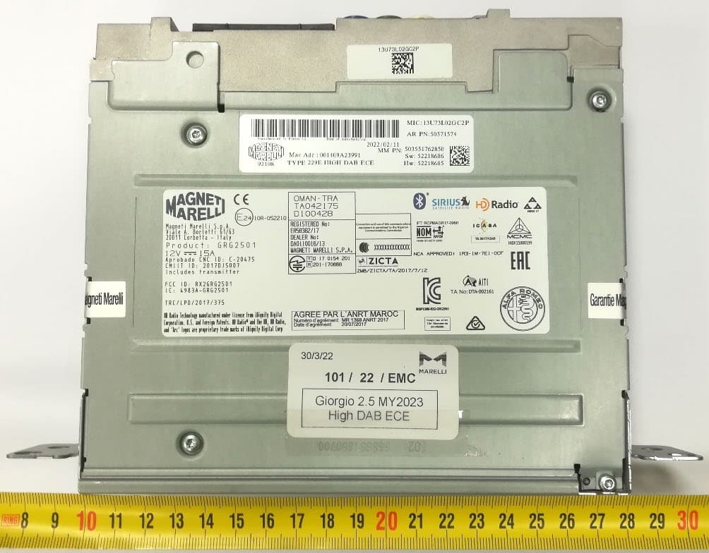
RX2GRG2501MY23
Jan 08, 2023Giorgio 2.5
Equipment Class
DSS - Part 15 Spread Spectrum Transmitter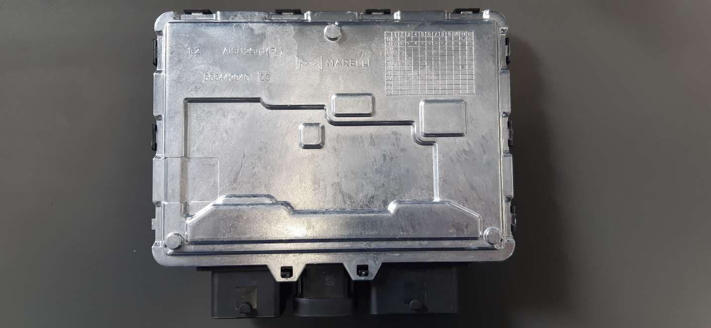
RX2BHD21
Apr 18, 2021Body Coputer Module
Equipment Class
DCD - Part 15 Low Power Transmitter Below 1705 kHz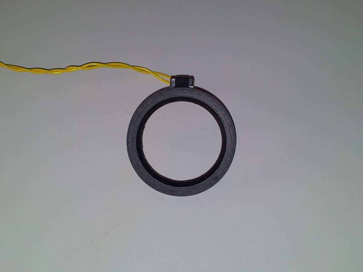
RX2BCML9
Jul 29, 2015Vehicle Immobilizer
Equipment Class
DCD - Part 15 Low Power Transmitter Below 1705 kHz