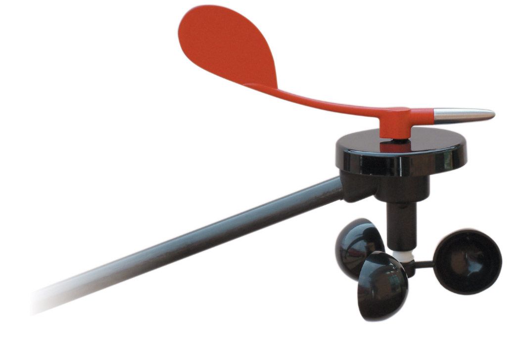
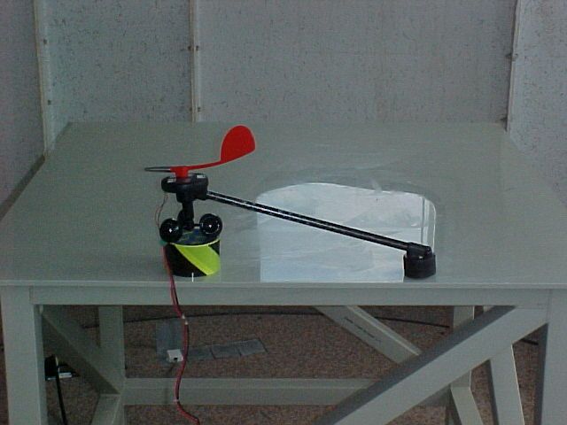
RX9-T120-916mn100 Wind Transmitter
Raymarine Belgium Bvba
Click to zoom
Application Details
- Equipment Class
- DXT - Part 15 Low Power Transceiver, Rx Verified
- Date of Grant
- Jul 08, 2004
- Application Purpose
- Original Equipment
- Date of Application
- Jul 08, 2004
- Equipment Note
- mn100 Wind Transmitter
- Frequency Range
- 916.00000000 - 916.00000000
- Company
- Raymarine Belgium Bvba
- Country
- United Kingdom
Documents & Files
Document Text
Text extracted from the exhibit documents filed with the FCC. Open a document above to read the original.
Users Manual
Wind Transmitter Tacktick Limited 22 North Street, Emsworth, Hampshire, PO10 7DG, England Tel. +44 (0)1243 379331 Fax. +44 (0) 1243 379199 www.tacktick.com Tools Required Parts List 1. Drill Bit 2. Power Drill 3. Cross Head Screwdriver 1. Masthead Mounting Plate 2. Wind Transducer 3. Mounting Screws (3 off) Precautions Carry out the “Auto Network” procedure and make sure the unit is operating correctly BEFORE attaching the Wind Transmitter to the masthead. Ensure that there is enough surface area at the top of the mast to attach the Transmitter Base. Check to make sure that the vane and anemometer cups are moving freely. Positioning Advise uu043 rev. 7 Wind Transmitter Tacktick Limited 22 North Street, Emsworth, Hampshire, PO10 7DG, England Tel. +44 (0)1243 379331 Fax. +44 (0) 1243 379199 www.tacktick.com Tools Required Parts List 1. Drill Bit 2. Power Drill 3. Cross Head Screwdriver 1. Masthead Mounting Plate 2. Wind Transducer 3. Mounting Screws (3 off) Precautions Carry out the “Auto Network” procedure and make sure the unit is operating correctly BEFORE attaching the Wind Transmitter to the masthead. Ensure that there is enough surface area at the top of the mast to attach the Transmitter Base. Check to make sure that the vane and anemometer cups are moving freely. Positioning Advise uu043 rev. 7 Installation Method 1. Complete the auto-networking procedure (described on the yellow instruction sheet) at deck level and ensure that Wind Speed and Angle are being displayed on the instruments. 2. Get an authorised dealer to ascend the mast and carefully mark and drill the three mounting holes using the supplied Template. Care should be taken to ensure the Template is positioned facing forward. 3. Secure the Wind Transmitter to the masthead using the three self tapping screws provided. NOTE: It may be necessary to use alternative mounting screws or bolts depending on the masthead plate. 4. Check for smooth and free operation of the anemometer cups and the windvane feather before de scending to deck level. WARNING: Always ensure that you are secured correctly before ascending any mast. Always attach a safety strap to the masthead whilst you are working and leave a competent person on deck to assist. If in doubt get a professional to ascend the mast. What Next Refer to the instrument handbook for details on calibration and alignment. Installation Method 1. Complete the auto-networking procedure (described on the yellow instruction sheet) at deck level and ensure that Wind Speed and Angle are being displayed on the instruments. 2. Get an authorised dealer to ascend the mast and carefully mark and drill the three mounting holes using the supplied Template. Care should be taken to ensure the Template is positioned facing forward. 3. Secure the Wind Transmitter to the masthead using the three self tapping screws provided. NOTE: It may be necessary to use alternative mounting screws or bolts depending on the masthead plate. 4. Check for smooth and free operation of the anemometer cups and the windvane feather before de scending to deck level. WARNING: Always ensure that you are secured correctly before ascending any mast. Always attach a safety strap to the masthead whilst you are working and leave a competent person on deck to assist. If in doubt get a professional to ascend the mast. What Next Refer to the instrument handbook for details on calibration and alignment.
Block Diagram
Tacktick Limited T120 Wind Block Diagram Microprocessor, circuit inc programming port, supervisor and voltage reference devices Optical wind speed measurement circuit Internal batteries and recharging circuit (Internal solar cells) Radio transceiver circuit Digital power rail Data and control sentences Wire Antenna RF Data on radio network Wind speed drive signals Wind speed data signals Magnetic wind direction measurement circuit Wind direction drive signals Wind direction data signals
Cover Letter(s)
Tacktick Limited Registered 3171270 England & Wales. 22 North Street Emsworth Hampshire P010 7DG England VAT: GB 640 8465 34 Directors: Clive Johnson, Mark Johnson BA MIEE CEng MBA T T a a c c k k t t i i c c k k L L i i m m i i t t e e d d 2 2 2 2 N N o o r r t t h h S S t t r r e e e e t t , , E E m m s s w w o o r r t t h h H H a a m m p p s s h h i i r r e e , , P P O O 1 1 0 0 7 7 D D G G . . E E n n g g l l a a n n d d T T e e l l : : + + 4 4 4 4 ( ( 0 0 ) ) 1 1 2 2 4 4 3 3 3 3 7 7 9 9 3 3 3 3 1 1 F F a a x x : : + + 4 4 4 4 ( ( 0 0 ) ) 1 1 2 2 4 4 3 3 3 3 7 7 9 9 1 1 9 9 9 9 E E - - m m a a i i l l : : s s a a l l e e s s @ @ t t a a c c k k t t i i c c k k . . c c o o . . u u k k W W e e b b : : w w w w w w . . t t a a c c k k t t i i c c k k . . c c o o . . u u k k 2 2 0 0 0 0 3 3 D D A A M M E E A A w w a a r r d d ( ( O O v v e e r r a a l l l l W W i i n n n n e e r r ) ) 2 2 0 0 0 0 3 3 C C o o n n c c o o u u r r s s I I n n n n o o v v a a t t i i o o n n A A w w a a r r d d 2 2 0 0 0 0 1 1 D D A A M M E E A A w w a a r r d d ( ( W W i i n n n n e e r r E E l l e e c c t t r r o o n n i i c c c c a a t t e e g g o o r r y y ) ) 1 1 9 9 9 9 9 9 D D A A M M E E A A w w a a r r d d ( ( W W i i n n n n e e r r E E l l e e c c t t r r o o n n i i c c c c a a t t e e g g o o r r y y ) ) 1 1 9 9 9 9 9 9 M M i i l l l l e e n n n n i i u u m m P P r r o o d d u u c c t t ( ( R R a a c c e e M M a a s s t t e e r r ) ) 1 1 9 9 9 9 8 8 M M i i l l l l e e n n n n i i u u m m P P r r o o d d u u c c t t ( ( R R a a c c e e C C o o m m p p a a s s s s ) ) 1 1 9 9 9 9 7 7 H H a a m m p p s s h h i i r r e e B B u u s s i i n n e e s s s s I I n n n n o o v v a a t t i i o o n n A A w w a a r r d d 28 th April 2004 Telecommunication Certification Body Radio Frequency Investigation Ltd. Ewhurst Park Ramsdell Basingstoke Hampshire RG26 5RQ England Subject: Certification Application FCC ID: RX9-T120-916 It is requested that the following information is to be held confidential on behalf of Tacktick Ltd. FCC Rules Part 0.459 refers. Tacktick Limited T120 Circuit Diagram.doc Tacktick Limited T120 BOM.xls Tacktick Limited T120 Radio Circuit Diagram.doc With regard to the above, the listed information discloses design details that are commercial in confidence to Tacktick Ltd. Tacktick Ltd are currently the only manufacturers of solar-powered, radio-networked marine electronics. By virtue of Tacktick ‘s combined technical knowledge and experience of solar cell performance and low-power design techniques, it is estimated that current competitors in the leisure marine market may take up to 18 months to reach the same level of knowledge. This is a significant commercial advantage, maintained by the non-disclosure of current design methodologies. To this end, Tacktick does not release the above documentation for public scrutiny either as part of the product documentation or to its supplier/dealer network. Yours Sincerely, Paul Jennings Design Consultant.
Cover Letter(s)
Tacktick Limited Registered 3171270 England & Wales. 22 North Street Emsworth Hampshire P010 7DG England VAT: GB 640 8465 34 Directors: Clive Johnson, Mark Johnson BA MIEE CEng MBA T T a a c c k k t t i i c c k k L L i i m m i i t t e e d d 2 2 2 2 N N o o r r t t h h S S t t r r e e e e t t , , E E m m s s w w o o r r t t h h H H a a m m p p s s h h i i r r e e , , P P O O 1 1 0 0 7 7 D D G G . . E E n n g g l l a a n n d d T T e e l l : : + + 4 4 4 4 ( ( 0 0 ) ) 1 1 2 2 4 4 3 3 3 3 7 7 9 9 3 3 3 3 1 1 F F a a x x : : + + 4 4 4 4 ( ( 0 0 ) ) 1 1 2 2 4 4 3 3 3 3 7 7 9 9 1 1 9 9 9 9 E E - - m m a a i i l l : : s s a a l l e e s s @ @ t t a a c c k k t t i i c c k k . . c c o o . . u u k k W W e e b b : : w w w w w w . . t t a a c c k k t t i i c c k k . . c c o o . . u u k k 2 2 0 0 0 0 3 3 D D A A M M E E A A w w a a r r d d ( ( O O v v e e r r a a l l l l W W i i n n n n e e r r ) ) 2 2 0 0 0 0 3 3 C C o o n n c c o o u u r r s s I I n n n n o o v v a a t t i i o o n n A A w w a a r r d d 2 2 0 0 0 0 1 1 D D A A M M E E A A w w a a r r d d ( ( W W i i n n n n e e r r E E l l e e c c t t r r o o n n i i c c c c a a t t e e g g o o r r y y ) ) 1 1 9 9 9 9 9 9 D D A A M M E E A A w w a a r r d d ( ( W W i i n n n n e e r r E E l l e e c c t t r r o o n n i i c c c c a a t t e e g g o o r r y y ) ) 1 1 9 9 9 9 9 9 M M i i l l l l e e n n n n i i u u m m P P r r o o d d u u c c t t ( ( R R a a c c e e M M a a s s t t e e r r ) ) 1 1 9 9 9 9 8 8 M M i i l l l l e e n n n n i i u u m m P P r r o o d d u u c c t t ( ( R R a a c c e e C C o o m m p p a a s s s s ) ) 1 1 9 9 9 9 7 7 H H a a m m p p s s h h i i r r e e B B u u s s i i n n e e s s s s I I n n n n o o v v a a t t i i o o n n A A w w a a r r d d 28 th April 2004 Telecommunication Certification Body Radio Frequency Investigation Ltd. Ewhurst Park Ramsdell Basingstoke Hampshire RG26 5RQ England Subject: Certification Applications FCC IDs: RX9-T110-916, RX9-T120-916, RX9-T122-916 Dear Nick, With regards to the above applications, Tacktick Ltd wish to declare the following, in line with the testing regime followed for these applications: RX9-T110-916 covers the individual products: T110 mn100 Digital display, T111 mn100 Dual Digital Display, and T112 mn100 Analogue Display – all being identical apart from the LCD layout. RX9-T122-916 covers both the T122 mn100 NMEA Interface and T121 mn100 Hull Transmitter – both being identical apart from PCB orientation and connector fit/labelling. RX9-T120-916 covers the single unique product T120 mn100 Wind Transmitter only. Yours Sincerely, Paul Jennings. Design Consultant.
Internal Photos
Internal Photographs Top Bottom
Operational Description
Tacktick Limited T120 Wind Operational Description Introduction This document is to be read in conjunction with the ‘Tacktick Limited T120 Wind Block Diagram’. The functionality of each block shown on the diagram is expanded in this document. Microprocessor This device stores the operating software in its on board flash and system data in its on board RAM. The software controls the operation of the T120 Wind Transmitter. The software can be upgraded in circuit by connecting the programming port to a PC running the appropriate development environment. The microprocessor uses a precision voltage reference against which to measure inputs through its built in 8 channel ADC. An external supervisor chip is used to ensure that the microprocessor is reset if it fails to produce a periodic strobe signal. Batteries and Recharging Circuit The unit runs from two internal, rechargeable lithium coin cells. These cells can be recharged using the integral solar cells. Magnetic Wind Direction Measurement Circuit The microprocessor provides an output signal that excites the wind direction measurement circuit. This circuit interacts with a permanent magnet in the rotating vane on top of the unit. The direction measurement circuit produces signals that are read through ADC inputs on the microprocessor. This data is used to determine the current angle of the wind vane. Optical Wind Speed Measurement Circuit The microprocessor drives an optical sensor that counts the rotations of a printed disk that is connected to the rotor cups on the wind transducer. The return signals from the sensor are counted by the microprocessor and the data is used to determine the current rotation speed of the cups. Radio Transceiver Circuit and PCB Antenna The unit communicates with other units in the network across a wireless data link. The microprocessor sends configuration sentences to the radio transceiver chip. The data link between the microprocessor and the radio chip is half duplex. The RF signals are transmitted / received using a simple monopole wire antenna.
Test Report
Radio Frequency Investigation Ltd, Ewhurst Park, Ramsdell, Basingstoke, Hampshire, RG26 5RQ, ENGLAND. Tel: +44 (0) 1256 851193 Fax: +44 (0) 1256 851192 Registered in England, No. 211 7901. Registered Office: Ewhurst Park, Ramsdell, Basingstoke, Hampshire RG26 5RQ TESTING 0644 TEST REPORT FROM RADIO FREQUENCY INVESTIGATION LTD. Test Of: Tacktick Ltd. Micronet mn100 T120 Wind Transmitter To: FCC Part 15.249 Test Report Serial No: RFI/MPTB1/RP44514JD20A This Test Report Is Issued Under The Authority Of Richard Jacklin, Operations Director: Checked By: Tony Henriques Tested By: Elin Danielson Release Version No: PDF01 Issue Date: 15 March 2004 Test Dates: 22 January 2004 to 06 February 2004 This report is issued in Adobe Acrobat portable document format (PDF). It is only a valid copy of the report if it is being viewed in PDF format with the following security options not allowed: Changing the document, Selecting text and graphics, Adding or changing notes and form fields. Furthermore, the date of creation must match the issue date stated above. This report may be copied in full. The results in this report apply only to the sample(s) tested. RADIO FREQUENCY INVESTIGATION LTD TEST REPORT S.No. RFI/MPTB1/RP44514JD20A Operations Department Page 2 of 30 Issue Date: 15 March 2004 Test Of: Tacktick Ltd. Micronet mn100 T120 Wind Transmitter To: FCC Part 15.249 This page has been left intentionally blank. RADIO FREQUENCY INVESTIGATION LTD TEST REPORT S.No. RFI/MPTB1/RP44514JD20A Operations Department Page 3 of 30 Issue Date: 15 March 2004 Test Of: Tacktick Ltd. Micronet mn100 T120 Wind Transmitter To: FCC Part 15.249 Table of Contents 1. Client Information..........................................................................................................4 2. Equipment Under Test (EUT) .......................................................................................5 3. Methods And Procedures.............................................................................................7 4. Deviations From The Test Specification .....................................................................8 5. Operation Of The EUT During Testing ........................................................................9 6. Summary Of Test Results...........................................................................................10 7. Measurements, Examinations And Derived Results................................................11 8. Test Results .................................................................................................................12 9. Measurement Methods ...............................................................................................24 10. Measurement Uncertainty ........................................................................................27 Appendix 1. Test Equipment Used ................................................................................28 Appendix 2. Test Configuration Drawings....................................................................29 RADIO FREQUENCY INVESTIGATION LTD TEST REPORT S.No. RFI/MPTB1/RP44514JD20A Operations Department Page 4 of 30 Issue Date: 15 March 2004 Test Of: Tacktick Ltd. Micronet mn100 T120 Wind Transmitter To: FCC Part 15.249 1. Client Information Company Name: Tacktick Ltd. Address: 22 North Street Emsworth Hampshire PO10 7DG Contact Name: Mr M. Johnson RADIO FREQUENCY INVESTIGATION LTD TEST REPORT S.No. RFI/MPTB1/RP44514JD20A Operations Department Page 5 of 30 Issue Date: 15 March 2004 Test Of: Tacktick Ltd. Micronet mn100 T120 Wind Transmitter To: FCC Part 15.249 2. Equipment Under Test (EUT) The following information (with the exception of the Date of Receipt) has been supplied by the client: 2.1. Identification Of Equipment Under Test (EUT) Brand Name: Micronet mn100 Model Name or Number: T120 Wind Transmitter Serial Number: 0401/00002 (for sample used to perform transmit measurements) 0307/00498 (for sample used to perform receive measurements) FCC ID RX9-T120-916 Country of Manufacture: UK Date of Receipt: 29 January 2004 2.2. Description Of EUT The equipment under test is a low power radio networked leisure marine instrumentation wind speed and direction transmitter. 2.3. Modifications Incorporated In EUT For the purposes of testing only (i.e. to allow testing of transmitter parameters to be performed), a sample of the EUT was software modified to increase the ‘transmit on’ time to 250 mS every second from the normal (and very low) operating mode duty cycle ‘transmit on’ time. Additionally the EUT was modified to provide a direct connection point to the internal 3V rails (post charging circuit) for an external 3V DC power supply. This was necessary to allow the EUT to operate at this increased transmission rate as the internal battery supply (which is recharged by solar panels) is not rated for this extended transmission rate and would discharge very quickly i.e. the EUT would no longer operate in this test mode. RADIO FREQUENCY INVESTIGATION LTD TEST REPORT S.No. RFI/MPTB1/RP44514JD20A Operations Department Page 6 of 30 Issue Date: 15 March 2004 Test Of: Tacktick Ltd. Micronet mn100 T120 Wind Transmitter To: FCC Part 15.249 2.4.Additional Information Related To Testing Power Supply Requirement: Internal battery supply of 3V (charged by solar panels) Intended Operating Environment: Marine Equipment Category: Mobile (in a boat) Type of Unit: Transceiver Interface Ports: None Transmit & Receive Frequency Range Fixed, Single frequency Channel ID Channel Number Channel Frequency (MHz) Transmit & Receive Channels Tested N/A N/A 916.0 MHz Occupied Bandwidth 200 kHz Highest Unintentionally Generated Frequency 916.07 MHz Maximum Fieldstrength @ 3 metres 92.2 dBμV/m 2.5. Support Equipment No support equipment was used to exercise the EUT during testing. RADIO FREQUENCY INVESTIGATION LTD TEST REPORT S.No. RFI/MPTB1/RP44514JD20A Operations Department Page 7 of 30 Issue Date: 15 March 2004 Test Of: …
Text truncated - open the document above for the full version.
Contact Information
Applicant
Andrew Little(Mr)
Technical Contact
Tacktick LtdChris Hodgson
+44 1243 379331
22 North St · Hants · United Kingdom
Test Firm
RFI Global Services Ltd.Allan Hume
Technical Specifications
| # | Rule Parts | Frequency Range | Power Output |
|---|---|---|---|
| 1 | 15C | 916 MHz - 916 MHz | - |
Other Applications from Raymarine Belgium Bvba

RX9-T070-916
Mar 25, 2007TACTICAL RACE COMPASS AND WIND SHIFT INDICATOR
Equipment Class
DXX - Part 15 Low Power Communication Device Transmitter
RX9-T113-916
Mar 25, 2007PORTABLE MULTIFUNCTION DISPLAY AND REMOTE
Equipment Class
DXX - Part 15 Low Power Communication Device Transmitter
RX9-T122-916
Jul 07, 2004mn100 NMEA Interface/Hull Transmitter
Equipment Class
DXT - Part 15 Low Power Transceiver, Rx Verified
RX9-T110-916
Jul 07, 2004mn100 Display
Equipment Class
DXT - Part 15 Low Power Transceiver, Rx Verified