RXF104MYSPOT REMOTE CONTROLLED PARKING BARRIER-RX
Designated Parking Corp.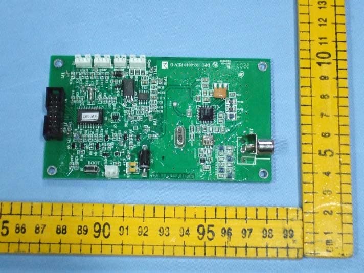
Click to zoom
Application Details
- Equipment Class
- CYY - Communications Receiver used w/Pt 15 Transmitter
- Date of Grant
- Sep 18, 2007
- Application Purpose
- Original Equipment
- Date of Application
- Sep 18, 2007
- Equipment Note
- MYSPOT REMOTE CONTROLLED PARKING BARRIER-RX
- Frequency Range
- 433.92000000 - 433.92000000
- Company
- Designated Parking Corp.
- Country
- United States
Documents & Files
Document Text
Text extracted from the exhibit documents filed with the FCC. Open a document above to read the original.
Users Manual
Designated Parking Corp V17 page 24 www.dp-corp.com FCC THIS DEVICE COMPLIES WITH PART 15 OF THE FCC RULES. OPERATION IS SUB-JECT TO THE FOLLOWING TWO CONDITIONS: (1) THIS DEVICE MAY NOT CAUSE HARMFUL INTERFERENCE, AND (2) THIS DEVICE MUST ACCEPT ANY INTERFERENCE RE-CEIVED,INCLUDING INTERFERENCE THAT MAY CAUSE UNDESIRED OPERATION. THE MANUFACTURER IS NOT RESPONSIBLE FOR ANY RADIO OR TV INTERFERENCE CAUSED BY UNAUTHORIZED MODIFICATIONS TO THIS EQUIPMENT. SUCH MODIFICATIONS COULD VOID THE USER’S AUTHORITY TO OPERATE THE EQUIPMENT. CE Hereby, Designated Parking Corp., declares that MySpot 202 is in compliance with the essential requirements and other relevant provisions of Directive 1999/5/EC . A copy of the Statement of Confor-mity can be found on the Company’s web site. Rudor M. Teich, President Express Installation Instructions 1. Clear area where unit is to be installed 2. Assemble barrier to the stubs of the 2 pods using security bolts 3. Position plates using template 4. Apply adhesive to the bottoms of the mounting plates and press them into place 5. Attach pods to plates 6. Wait for adhesive to cure before driving or stepping over barrier. 10 Ridge Road West Orange, NJ 07052-4018 USA www.dp-corp.com Email [email protected] Tel +1.973 669-8214 Fax +1.973 669-5161 Manual P/N : 92-1002 Revised 26APR2007 Copyright and Patents MySpot 200 is covered by design and utility patent applications and issued patents. MySpot is a trademark of Designated Parking Corp. Designated Parking Corp V17 page 1 www.dp-corp.com Installation Manual MySpot ™ 200 V4 Remote Controlled Parking Barrier Congratulations! MySpot 200 rugged construction, careful design and attention to detail will provide you with years of service and enjoyment. How-ever, like all things mechanical and electronic, proper and careful installation is essential in order for the product to perform as de-signed. We suggest that you keep this manual in the car’s glove com-partment, along with the Emer-gency Key/Security Wrench. The key allows you to manually lower the barrier. The wrench allows access to the Key. The User manual will refresh your memory how to do it, as well as show you how to recognize when the radio batteries need replacing and how to go about it. A summary installation proce-dure is available at the back of this manual. A pictorial man-ual is available separately. If external damage to the packing is evident, notify the carrier immediately. Shipping damage is not covered by the manufacturer’s warranty. WARNING ! Barrier may cause pedes- trian or users to trip over it. Please install and provide warning signs accordingly. Note that Public Liability should be in place. This manual applies to MySpot 200 version 4 (shipments after JUL 2006). MySpot 200 is installed as shown to block ac-cess to a parking space. On com-mand, the barrier falls forward to allow ac-cess. A video showing the installation is avail-able on www.dp-corp.com/downloads/videos Designated Parking Corp V17 page 2 www.dp-corp.com Kit Contents Below is a list of the main assemblies and parts in the carton. Please note the “Ref: des-ignator on the leftmost column. This ref will be used throughout the manual to identify parts and assemblies. Anchors and their bolts are not included in the kits and should be ordered separately. NOTE ( 4) K5 bolts, (2) K11 bolts and (6) K7 washers are used to fasten the PowerPod and the Idle- Pod, respectively, to the mounting plates during shi pping. These 6 bolts are not in the parts bag “kit” detailed below, and are listed in the part list above. Designated Parking Corp V17 page 23 www.dp-corp.com Can not Reboot Step Test YES NO 1 Is barrier in the UP position when trying to boot or change sensor setting? go to step 2 Configuration (“Boot”) Switch is ignored except when barrier is in the Locked Up position 2 Disconnect battery cable for 15 seconds, reconnect. Problem still exists? go to step 3 3 Replace batteries in PowerPod. Problem still exists? Replace elec- tronic module Designated Parking Corp V17 page 22 www.dp-corp.com Troubleshooting No response to Remote control Step Test YES NO 1 Is the correct button pushed and does indica- tor on remote control light up when button is pushed? go to step 2 Replace battery in remote control 2 Has this remote control worked before? go to step 2a Add remote control to memory of MySpot 200 3 Is barrier locked in Locked Up position? go to step 4 go to step 5 4 Use Emergency key to release barrier, then raise barrier manually slowly and retest. Is unit now working properly? Jam cleared go to step 6 5 Is barrier locked in Locked Down position? go to step 8 Bring barrier to locked up position and go to step 1 6 Is there another remote control that does control the unit? go to step 7 Replace batteries in the PowerPod . If this does not help, erase memory of MySpot (see manual) 7 Add remote control to memory of MySpot. Does it work? Done Replace remote control 8 With the barrier down, step on it a couple of times to simulate a car passing over the barrier with both wheels. Is the barrier responding the remote control? Done go to step 4 2a Has the barrier been slow to respond recently Replace PowerPod batteries go to step 3 Motor responds but no motion of barrier Step Test YES NO 1 Is barrier locked in Up position? go to step 2 Go to step 4 2 While motor sounds, push barrier down. Did it move? go to step 3 Open PowerPod cover and check operation 3 Check alignment of pods or a bent barrier Done 4 Is it locked in Down position? Step on the barrier and retest Step on barrier and compress spring, twice and re-test Step Test YES NO 2 Check wires from the optical sensors to the electronic module. Are cables dam- aged? Move wires away from edge Make sure opto is not subject to bright light during test Barrier goes up and then drops 1 “arm” the barrier by stepping on it and repeat the test. Problem exists? Go to step 2 It was due to barrier being manually manipu- lated and going out of synch. Desi…
Text truncated - open the document above for the full version.
Block Diagram
River Display Limited C O N F I D E N T I A L Title: RRC433SizeA3 Date of Revision: Sep 13, 2007Document Number: RRC433.SCH Sheet of 1 1 Printed on: 13-Sep-2007 REV A MCUSENSOR POWER CIRCUIT RECEIVER CIRCUIT 433.92MHZ ANTENNA DRIVER MOTOR DC IN CRYSTAL 26. 45125M 32.768K CRYSTAL 32. 768K
External Photos
Page 1 o f 2 FCC ID: RXF104 Anbotek Compliance Laboratory Limited Report No. 200708704R Figure 1 The EUT-Overall View Figure 2 Receiver of the EUT-Front View Page 2 o f 2 FCC ID: RXF104 Anbotek Compliance Laboratory Limited Report No. 200708704R Figure 3 Receiver of the EUT-Back View
ID Label/Location Info
FCC ID Label Sample for FCC ID: RXF104 FCC ID: RXF104 This device complies with Part 15 of the FCC Rules. Operation is subject to the following two conditions: 1. This device may not cause harmful interference, and 2. This device must accept any interference received, including interference that may cause undesired operation.
ID Label/Location Info
The proposed Label Location on EUT Proposed FCC ID Label Location
Internal Photos
Anbotek Compliance Laboratory Limited Report No. 200708704R Figure 1 Receiver of the EUT-Inside View Figure 2 Receiver of the EUT-Inside View
Operational Description
The theory of RRC433 module: 1: MCU: responsible for receiver.,to control driver motor . main frequency: 32.768KHz. 2: Driver motor: To control barrier raise or down. 3: Sensor: To check current state of barrier.. 4: Power circuit: To provide steady power to around circuit. 5: Receiver circuit: To receive signal of the transmit. Main frequency: 433.92MHz. 6: The Antenna is outside of pcb.
Schematics
GND BT16VBT2BT3BT4 Test 1 Vcc 2 P2.5 3 Vss 4 Xout 5 Xin 6 RST* 7 P2.0 8 P2.1 9 P2.2 10 P1.7 20 P1.6 19 P1.5 18 P1.4 17 P1.3 16 P1.2 15 P1.1 14 P1.0 13 P2.4 12 P2.3 11 U1MSP430F1121AIDW R4 340k 1% Q7 SI3460DV R5 510 R6 124k 1% Y1 32.768KHz R7 22k 1 2 3 4 5 6 7 8 9 10 11 12 13 14 H1 JTAG in 4 out 5 Vss 2 3 1 U2 TPS71533DCKR C1 0.1uF + C3 0.47uF TANT *************** C2 0.1uF Q8 MMBT2907A R8 100k R10 100k R1526.1K 1% R11 100k Q3 MMBT3904 R1647k D1RLR4004 R1747k GND GND GND GND GND GND GND GND GND R12100k R2110k R240 Q4MMBT3904 R1833k R1947k R2047k 5.0-7.5V 3.3V Q9 2SB08730R R2820 Q5MMBT3904 R13 100k GND R25 10k 12 H2Battery 123 H5 Opto_#2 123 H4Opto_#1 GND Motor (+) Out1LED1 Motor (-) Out2LED2 GND R28 1 Ohm 0805 *************** R2610k R2710k C5 0.033uF GND GNDGND R2310k GND C66pF C7 6pF GND + C810uF TANT *************** PCB 38-6010 Rev. F R3110k + C9 NU 12 BATTERY Q11 MMBT2907A R3233k Q12 MMBT2907A R33 100k 12 H3 Motor R3410k R35 0 OHM Power Vcc VBB VCC Motor_sensor Vmm Motor_onBat_senseBat_V_input VBB Vcc Shaft_Sensor Shaft_Sensor EnableRFS_onData_in VBB VCC Vcc ALL RESISTORS AND CAPACITORS ARE 0603 UNLESS NOTED. 3.3V Reboot S1 Reboot 0.825V Ref TP1 TP3 TP4 TP5 TP6 TP7 TP2 D2 1N5001 5 mSec OUTN 24 OUTP 23 VEE 22 RSSI 21 OAP 20 OAN 19 OUT-OA 18 17 VCC 25 VEE RO 26 VCC 27 ENRX 28 IN-LNA 31 LF 29 VEE 30 32 VCC VEE 1 GAIN-L 2 OUT-LNA 3 IN-MIX1 4 VEE 5 IF1P 6 IF1N 7 VCC 8 IN-DEM 16 OUT-IFA 15 VCC 14 FBC2 13 VEE 10 FBC1 12 IN-IFA 11 9 OUT-MIX2 IC101 TH71101 C127 2.2p C108 6pF / 8pF C106100pF FA101 CERFIL C11610nF C11810NFC11710NF C11510nF C103 100/15pF X101 26.45125/ 23.70625 Mhz R10210K C102 1nF C105100PF C114100NF C107680pF R104100K C11310nF RL105470 Vdd VDDNCNC NC NC C123 220pF L1038.2nH Vdd TP1 signal strength Vdd C101 100pF VDD RL106 470 R107390 J101 RCA F C1041000pF ENRX ENRX TP8 gnd 1 gnd 2 in 3 out 6 gnd 5 Vdd 4 U3 SGA-1263 Q1 Q2 VCC LNA LNA TP9 LNA-enable 1.5 mSec R147k R3 100k R947k R2956 IN-G 1 IN 2 CASE-G 3 OUT 5 O-GND 6 78 CASE-G 4 XF1B3555/NDF4900 saw filter C111 6.8pF/10pF L101 33nH/43nH C109 6.8pF/10pF L102 33nH/43nH C14 7pF C1128pF C15 8pF DESIGNATED PARKING CORP. CONFIDENTIAL Title :RRC MySpot 200 Controller 433/390MHz 433MHz Assembly 02-6010 Date of Revision: Sept 14,2006Document RRC_revG2.sch Sheet 1 of 1 REV: SizeTabloid G2 BT17.5V Vmm 48 23 1 U4A LMV358M RSSI R1433k R371M R226.8k R301k R3610k C111.5nF C10 6.8nF C12 0 ohm ENRX 56 7 U4B LMV358M RSSI Data Data Slicer Stage demodulates ASK R384.7k R39100 C131nF TP10 Rev F0: 10-18-04 C12 was 0.01, R36 was 100k, R37 was 10M C128 was NU L110/12nH L410/12nH L310/12nH L210/12nH C16 2pF C21 7pF C18 1.5pF C20 2pF C1910pF C1710pF Front -end filter redesigned; H2 was 3 pin 433/390 390MHz Assembly 02-6012 Rev F1: 10-20-04 Corrected 390MHz valuesRev F2: 12-16-04 L103 was 15nH C108 was 2.7/4.7pFRev F3 12-18-04 C108 was 4/6p, L1-L4 were 10nH 433MHz/390MHz R15a 85.6 K 1% Rev F5 Added R15 for 4 or 5 battery supply Remove R15a when using 4 batteries GND R4133k 1 2 3 H6Opto_Top LED R4210k GND VCC TP11 LED_on R40 0 LED ON Rev G0 7/3/06 Added H6 with its circuitryRev G1 8/24/06 Added C4Rev G2 9/14/06 Removed C4, R40,R24 were 510 ohm
Test Report
Page 1 o f 17 FCC ID: RXF104 Anbotek Compliance Laboratory Limited Report No. 200708704R FCC TEST REPORT On Behalf of Designated Parking Corp. FCC ID: RXF104 Myspot Remote Controlled Parking Barrier(Rx) Model No.: RRC-433 Prepared for : Designated Parking Corp. Address : 10 Ridge Road West Orange, NJ 07052 Prepared By : Anbotek Compliance Laboratory Limited Address : 2/F, Langfeng Building, Kefa Road North, Hi-tech Industrial Park, Nanshan District, Shenzhen 518057, China Tel: (86) 755-26014771 Fax: (86) 755-26014720 Report Number : 200708704R Date of Test : Sep.04~11, 2007 Date of Report : Sep.12, 2007 Page 2 o f 17 FCC ID: RXF104 Anbotek Compliance Laboratory Limited Report No. 200708704R TABLE OF CONTENTS Description Page Test Report Verification 1. GENERAL INFORMATION ............................................................................................................... 4 1.1. Description of Device (EUT) ..........................................................................................................................4 1.2. Description of Test Facility.............................................................................................................................5 1.3. Measurement Uncertainty ...............................................................................................................................5 2. RADIATED EMISSION MEASUREMENT....................................................................................... 6 2.1. Test Equipment ...............................................................................................................................................6 2.2. Block Diagram of Test Setup ..........................................................................................................................6 2.3. Radiated Emission Limit (Class B) .................................................................................................................7 2.4. EUT Configuration on Measurement ..............................................................................................................7 2.5. Operating Condition of EUT...........................................................................................................................7 2.6. Test Procedure.................................................................................................................................................8 2.7. Radiated Emission Measurement Results .......................................................................................................8 3. FCC ID LABEL...................................................................................................................................... 9 4. PHOTOGRAPH ................................................................................................................................... 10 4.1. Photo of Radiated Emission Measurement ...................................................................................................10 APPENDIX I (Radiated Emission Test Curves) (2 pages) APPENDIX II (Photos of EUT) (5 Pages) Page 3 o f 17 FCC ID: RXF104 Anbotek Compliance Laboratory Limited Report No. 200708704R Page 4 o f 17 FCC ID: RXF104 Anbotek Compliance Laboratory Limited Report No. 200708704R 1. GENERAL INFORMATION 1.1. Description of Device (EUT) Description : Myspot Remote Controlled Parking Barrier(Rx) Model Number : RRC-433 Test Power Supply : DC 7.5V Frequency : 433.92MHz Applicant : Designated Parking Corp. Address : 10 Ridge Road West Orange, NJ 07052 Manufacturer : River Display Electronics (Songgang) Mfg. C Address : Shapu Industry Zone, No. 3, Baoan District, Songgang, Shenzhen Date of Sample received : Aug.29, 2007 Date of Test : Sep.04~11, 2007 Page 5 o f 17 FCC ID: RXF104 Anbotek Compliance Laboratory Limited Report No. 200708704R 1.2. Description of Test Facility The test facility is recognized, certified, or accredited by the following organizations: VCCI-Registration No.: R-2197 and C-2383 SGS-CSTC Standards Technical Services Co., Ltd., EMC Laboratory has been registed and fully described in a report filed with the (VCCI) Voluntary Control Council for Interference by Information Technology Equipment. The acceptance letter from the VCCI is maintained in our files. Registration R-2197 and C-2383, September 29, 2005. FCC-Registration No.: 556682 SGS-CSTC Standards Technical Services Co., Ltd., EMC Laboratory has been registed and fully described in a report filed with the (FCC) Federal Communications Commission. The acceptance letter from the FCC is maintained in our files. Registration 556682, August 04, 2005. IC-Registration No.: 6002 SGS-CSTC Standards Technical Services Co., Ltd., EMC Laboratory has been registed and fully described in a report filed with the (IC) Industry Canada. The acceptance letter from the IC is maintained in our files. Registration 6002, August 25, 2005. Test Location All Emissions tests were performed at: SGS-CSTC Standards Technical Services Co., Ltd. at No.1 Workshop, M-10, Middle Section, Science & Technology Park, Shenzhen, China 1.3. Measurement Uncertainty Radiation Uncertainty : Ur = 4.26dB Conduction Uncertainty : Uc = 2.66dB Page 6 o f 17 FCC ID: RXF104 Anbotek Compliance Laboratory Limited Report No. 200708704R 2. RADIATED EMISSION MEASUREMENT 2.1. Test Equipment The following test equipments are used during the radiated emission measurement: 2.1.1. For Anechoic Chamber 2.2. Block Diagram of Test Setup 2.2.1. Block diagram of connection between the EUT and simulators (EUT: Myspot Remote Controlled Parking Barrier(Rx)) 2.2.2. Anechoic Chamber Test Setup Diagram (EUT: Myspot Remote Controlled Parking Barrier(Rx)) Item Equipment Manufacturer Model No.Serial No.Last Cal. Cal. Interval 1. Ultra-Broadband Antenna Rohde & SchwarzHL562 100015 Nov.12, 2006 1 Year 2. EMI Test ReceiverRohde & SchwarzESI26 100009 Nov.12, 2006 1 Year 3. EMI Test Software Rohde & SchwarzESK1 N/A N/A N/A 4. Bilog A…
Text truncated - open the document above for the full version.
Test Setup Photos
Anbotek Compliance Laboratory Limited Report No. 200708704R TEST SETUP PHOTOGRAPH Photo of Radiated Emission Measurement
Contact Information
Applicant
Rudor m Teich(President)
Test Firm
SGS-CSTC Standards Technical Services Co.,Ltd.June Zhang
Technical Specifications
| # | Rule Parts | Frequency Range | Power Output |
|---|---|---|---|
| 1 | 15B | 433.92 MHz - 433.92 MHz | - |
Other Applications from Designated Parking Corp.
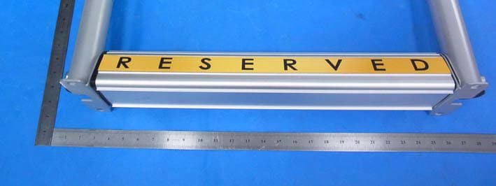
RXF141
Jan 26, 2015Parking barrier
Equipment Class
CYY - Communications Receiver used w/Pt 15 TransmitterRXF145
Jan 21, 2015Remote Control Transmitter
Equipment Class
DSC - Part 15 Security/Remote Control Transmitter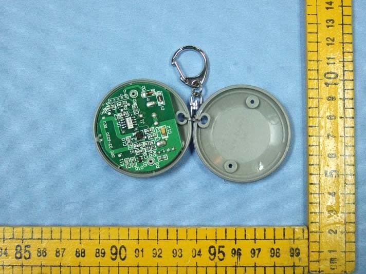
RXF103
Sep 18, 2007MYSPOT REMOTE CONTROLLED PARKING BARRIER-TX
Equipment Class
DSC - Part 15 Security/Remote Control Transmitter