RXSK570GSM/GPRS 1900 MHz Mobile Phone
CEC Wireless R&D Ltd.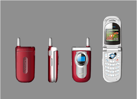
Click to zoom
Application Details
- Equipment Class
- PCE - PCS Licensed Transmitter held to ear
- Date of Grant
- May 05, 2004
- Application Purpose
- Original Equipment
- Date of Application
- May 05, 2004
- Equipment Note
- GSM/GPRS 1900 MHz Mobile Phone
- Frequency Range
- 1850.20000000 - 1909.80000000
- Company
- CEC Wireless R&D Ltd.
- Country
- China
Documents & Files
Document Text
Text extracted from the exhibit documents filed with the FCC. Open a document above to read the original.
Users Manual
Page 1 of 1 User’s Guide for K570 C570 and K570 are based on the same platform; most of their functions are same. The differences between them are that: C570 has FM Radio, while K570 has not; K570 has a small display above the clamshell; while C570 has not. Page 2 of 2 Table of Contents 1. General information 1.1 Keypad 1.1.1 Number keys 1.1.2 Control keys 1.1.3 Key operation in standby mode 1.2 Display 1.2.1 Main Display 1.2.2 Small Display 1.3 Installing the battery 1.4 Installing the SIM card 1.5 Charging the battery 1.6 256-color cool light 2. Basic operation 2.1 Turning on the mobile phone 2.2 Turning off the mobile phone 2.3 Placing a call 2.4 Answering a call 2.5 Text input methods 2.5.1 T9 intelligent English input T9智能英文 2.5.2 Symbol input 字符 2.5.3 Number input 数字 2.6 Phonebook 2.6.1 Searching an entry 2.6.2 Creating an entry 2.6.3 Phonebook list 2.6.4 Checking the phonebook capacity 2.6.5 Deleting all entries 2.6.6 Copying all entries 2.6.7 Moving all entries 2.6.8 Group setting 2.6.9 Selecting memory 2.6.10 IP call service number 2.6.11 Personal information 2.8 Data transfer between phone and PC 2.8.1 Download MIDI ring 2.8.2 Download standby screen display 2.8.3 Transfer phone to PC Page 3 of 3 3. Menu operation 3.5 Text message (network dependent) 3.5.1 Inbox 3.5.2 Outbox 3.5.3 Composing a text message 3.5.4 Setting up the text message box 3.5.5 Deleting text messages 3.5.6 Checking the capacity 3.5.7 Voicemail 3.5.8 Text message broadcast 3.1 Call record 3.1.1 Dialed calls 3.1.2 Answered numbers 3.1.3 Missed calls 3.1.4 Deleting a call list 3.1.5 Call meters 3.2 Mode settings 3.2.1 Personalized settings 3.3. Quick settings 3.4 Phone settings 3.4.1 Ringer types 3.4.2 Volume adjustment 3.4.3 Phone settings 3.4.4 Call settings 3.4.5 Time setting 3.4.6 Security 3.4.7 Safeguard 3.4.8 Network 3.4.9 Factory setting 3.3 Call forward (network dependent) 3.5.1 Unconditional call forward 3.5.2 Call forward when busy 3.5.3 Call forward when not answered 3.5.4 Call forward when not reachable 3.5.5 Canceling call forward Page 4 of 4 3.5.6 Checking status 3.8 Advanced operations 3.8.1 Organizer 3.8.2 Alarm clock 3.8.3 Calculator 3.8.4 Stopwatch 3.8.5 Timer 3.8.6 World time 3.6.7 Biological clock 3.6 Entertainment 3.6.1 FM radio 3.6.2 Game 3.6.3 Mobile QQ (network dependent) 3.6.4 Biological clock 3.7 WAP (network dependent) 3.7.1 Homepage 3.7.2 Bookmark 3.7.3 Webpage visited last time 3.7.4 Navigation 3.7.5 Settings 3.9 STK service (network dependent) 4. Accessories 4.1 Earphones 4.2 Charger 4.3 Data cable 4.4 5. Safety precautions 6. Care and maintenance Page 5 of 5 1. General information 手机介绍 Earphone jack 耳机插孔 Antenna 天线 Left soft key 左软键 Volume key 侧面上下键 Left key 左键 FM radio key 侧面多媒体键 Send key / answer 发送键 Clear key 删除键 Built-in speaker 听筒 Up key 上键 Right soft key 右软键 Enter key 确定键 Right key 右键 Down key 下键 Power/End key 电源键/挂断键 Number keys 数字键 Microphone 话筒 Page 6 of 6 1.1 Keypad 键盘区 Your mobile phone has 25 keys and can be divided into two parts: z Number/letter keys, 12 keys in all z Control keys, 13 keys in all 1.1.1 Number/letter keys 数字/字母键 There are 12 number/letter keys, that is, 0 to 9 and the "*" key and "#" key. You can use these keys to input numbers or letters/symbols and pressing a key may correspond to different results as listed below: Editor input 编辑器输入内容 Letter 字符 Number 数字 Calculator 计算器 Key icon 键盘标签 Capital letter Small letter Press brieflyPress and hold 1 Space Space * Conversion among input modes Conversion among input modes # Press briefly: conversion between capital and small letters Press and hold: symbol input Press briefly: conversion between capital and small letters Press and hold: symbol input 1.1.2 Control keys 控制键 Power/End key 电源键/挂断键 Red key in the right part of the keypad. z Press to power on the phone. Press and hold during the charging process. z Press and hold to power off the phone. z Press briefly to return to the standby mode from a menu or editing mode. z Press to end a call. z Press to refuse to answer a call. z From standby mode or the FM menu, press briefly to turn off the FM radio that has been activated. Send key / Answer key 发送键/接听键 Green key in the left part of the keypad. Press to place or answer a call. From standby mode, press to access dialed calls. Page 7 of 7 Left soft key and right soft key 左软键和右软键 The left soft key is in the upper left corner of the keypad and the right soft key is in the upper right corner of the keypad. Their functions are indicated at the bottom of the screen. Navigation Keys 方向键 There are four navigation keys, namely, Right, Left, Up and Down. Up and Down: 上键和下键 z Scroll to show the letters/symbols available for selection in the editor. z Scroll to view menus and lists. z Scroll to read messages or other texts. z Scroll to search a program in the FM mode. Note: The Up/Down keys feature auto repeat. When pressing and holding either one of these two keys, it acts as being pressed many times, i.e. when pressing the key firmly, after a lapse of time, the auto repeat function will be activated. The lapse of time required to activated the function has been preset and cannot be modified. Left and Right: 左键和右键 z Scroll to move the cursor in the editor. z Scroll to select the program name in the FM mode. Enter Key (Ok key) 确定键 The key in the center of the navigation keys. Press to confirm. Clear Key 删除键 Also known as Back key. When editing, press briefly to delete the previous character, or if there is no previous character, delete the subsequent characters in sequence. Press and hold to delete all the characters. Press to return to the previous display. Press and hold to return to the standby mode. When viewing menus, pess briefly to return to the previous menu. Press and hold to return to the standby mode. Side Keys 侧面键 Including the volume key and the FM radio key. z When the flip is closed and the earphone is attached, press briefly any of them to answer an incoming call. z When the flip is closed, press and hol…
Text truncated - open the document above for the full version.
External Photos
EXHIBIT C - EUT PHOTOGRAPHS K570 – Front, Rear, Side and Open View K570 Earpiece – Top View K570 Power Adapter – Top View
ID Label/Location Info
EXHIBIT A - FCC ID LABELING AND WARNING STATEMENT Proposed FCC ID Label FCC ID: RXSK570 Specifications: Text is black or white in color and is left justified. Labels are silk-screened and shall be “permanently affixed” at a conspicuous location on the EUT. Proposed Label Location on EUT Back View of the EUT/Proposed ID Label Location FCC ID: R X SK570 K570 FCC Warning Statement A FCC Warning Statement is provided in the product manual.
Internal Photos
K570 – Solder View K570 – Component View Antenna Photo
Operational Description
Model : K570 Vision : 03 Date : 2004-3-15 Tuning Up procedure & Operational Manual Page No. : 第 44 页 共 44 页 The information disclosed herein is proprietary to and is not to be used by or disclosed to unauthorized person(s) without the written consent of CEC Wireless. The recipient of this document shall respect the security status of the information 44 Main board connector: 5.0 Operational Manual In this part, the operation process is explained by the interfaces. Carkit I/O ( PIN 18 to PIN1 from left to right) Ant. Con. PIN15 PIN1 LCD Con. PIN16PIN30 PIN6 PIN5 PIN4 SIM PIN3 Ear. Ji g 16 . . . . 1 TP314 TP311 TP312 TP315 TP310 TP313 TP304 TP303 TEMP BAKUPBAT Model : K570 Vision : 03 Date : 2004-3-15 Tuning Up procedure & Operational Manual Page No. : 第 45 页 共 45 页 The information disclosed herein is proprietary to and is not to be used by or disclosed to unauthorized person(s) without the written consent of CEC Wireless. The recipient of this document shall respect the security status of the information 45 Solution and its interfaces 5.1 GPIO The GPIO signals are used as general-purpose I/O pins for various functions. A description of the usage of these pins is shown in table 5.1 GPIO Name/definition GPIO(0) SPEED_MODE GPIO(1) FM_DATA GPI0(2) AMP_EN GPIO(3) CHARGE_REVE RSE GP1O(4) CHARGE_MOD E GPIO(5) CAMERA_EN GPIO(6) FM_CLK GPIO(7) FLIP_SENSE Model : K570 Vision : 03 Date : 2004-3-15 Tuning Up procedure & Operational Manual Page No. : 第 46 页 共 46 页 The information disclosed herein is proprietary to and is not to be used by or disclosed to unauthorized person(s) without the written consent of CEC Wireless. The recipient of this document shall respect the security status of the information 46 GPIO(8) FM_NR_W GPIO(9) TEST_CTS(CTS 0) GPIO(10) CHARGE_PULS E_IT Table 5.1 GPIO Interfaces 5.2 GPON The GPON signals are used as general purpose on pins. A description of the usage of these pins is shown in table 5.2. Table 5.2 GPON Interfaces 5.3 RFSIG The RFSIG signals are used to control the various functions of the RF-part. A description of the Usage of these pins is shown in table 5.3 Model : K570 Vision : 03 Date : 2004-3-15 Tuning Up procedure & Operational Manual Page No. : 第 47 页 共 47 页 The information disclosed herein is proprietary to and is not to be used by or disclosed to unauthorized person(s) without the written consent of CEC Wireless. The recipient of this document shall respect the security status of the information 47 Table 5.3 RFSIG descriptions 5.4 AUXDAC / AUXADC The AUXDAC / AUXADC signals are used to control and measure some functions of the RF-part. A description of the usage of these pins is shown in table 5.4. Table 5.4 AUXDAC/AUXADE Interfaces 5.5 3WBUS The 3-wire bus is used to program the transceiver and baseband. These signals are also available on the ST1 connector in the emulation part. Model : K570 Vision : 03 Date : 2004-3-15 Tuning Up procedure & Operational Manual Page No. : 第 48 页 共 48 页 The information disclosed herein is proprietary to and is not to be used by or disclosed to unauthorized person(s) without the written consent of CEC Wireless. The recipient of this document shall respect the security status of the information 48 Table 5.5 3WBUS Interfaces 5.6 SIOX / SIOY The SIOX and the SIOY bus are used for communication between BB and BAI. Testing is provided by test points inside the phone application area and by signals on ST1 in the emulation part. Table 5.6 SIOX/SIOY Interfaces 5.7 UART0 / UART1 The UART0 part provides an interface for communication with an external terminal. This communication uses automatic baud-rate detection and hardware handshake. The UART0 can be switched off by software using the line CMD_UART (GPIO 6) if this option is implemented. In that case, lines TEST_RXD and TEST_TXD are disconnected from bottom connector (BU2). Power supply for the UART0 block is VDD2. The UART1 part provides interface for communication with an external terminal and can be Model : K570 Vision : 03 Date : 2004-3-15 Tuning Up procedure & Operational Manual Page No. : 第 49 页 共 49 页 The information disclosed herein is proprietary to and is not to be used by or disclosed to unauthorized person(s) without the written consent of CEC Wireless. The recipient of this document shall respect the security status of the information 49 used only for tracking and testing. This UART does not provide any hardware handshake or automatic baud-rate detection. The signal RXD1 will be used for recognizing future external devices. Power supply for the UART1 block is VDD2. Table 5.7 UART Interfaces 5.8 LF_INTERFACE The LF_INTERFACE signals are used for audio signals from the microphone and to the earpiece as well as for the hands free. A description of the usage of these signals is shown in table 5.8. Table 5.8 LF Interfaces 5.9 SIM On the K570 Design there are two SIM card connectors. One is in the “phone application” area (ST4) to show the position inside the design and the second one (ST5) is in the emulation area Model : K570 Vision : 03 Date : 2004-3-15 Tuning Up procedure & Operational Manual Page No. : 第 50 页 共 50 页 The information disclosed herein is proprietary to and is not to be used by or disclosed to unauthorized person(s) without the written consent of CEC Wireless. The recipient of this document shall respect the security status of the information 50 for testing the K570 Reference Design. The SIM-card is accessed via the SIM interface. A description of the usage of these signals is shown in table 5.9 Pins Definition Pin1 Pin2 VCC for SIM Pin3 VCC for SIM Pin4 Reset for SIM Pin5 Data line of SIM Pin6 Clock for SIM Table 5.9 SIM definitions 5.10 KBIO The keyboard is organized as a triangular matrix as shown in Table 5.10. The KBIO pins are available on the EVITA connector (ST2) and on separate KEYBOARD connector (ST3) in the emulation area to have the possibility to connect an external keyboard for ease of use (see figure 5.1). Table 5.10 KBIO Interfaces Model : K570…
Text truncated - open the document above for the full version.
Operational Description
Model : K570 Vision : 03 Date : 2004-3-15 Tuning Up procedure & Operational Manual Page No. : 第 1 页 共 1 页 The information disclosed herein is proprietary to and is not to be used by or disclosed to unauthorized person(s) without the written consent of CEC Wireless. The recipient of this document shall respect the security status of the information 1 CONTENT 1.0 Objective 2.0 Abbreviation and glossary 3.0 Tuning up procedure 4.0 Reference 5.0 Operational Manual Model : K570 Vision : 03 Date : 2004-3-15 Tuning Up procedure & Operational Manual Page No. : 第 2 页 共 2 页 The information disclosed herein is proprietary to and is not to be used by or disclosed to unauthorized person(s) without the written consent of CEC Wireless. The recipient of this document shall respect the security status of the information 2 1.0 Objective This document is intended for FCC testing; it mainly includes Tuning Up Procedure and Operational Manual. It describes the key principles of K570; its tuning up, its operation among the interfaces and its antenna features. 2.0 Abbreviation and glossary 3WBUS Three-Wired BUS (Signalname) AUXADC AUXilary Analog Digital Converter (Signalname) AUXDAC AUXilary Digital Analog Converter (Signalname) BB Baseband BAI Baseband Audio Interface COMBO Multi chip package consisting FLASH and SRAM CPU Central Processing Unit CSx Chip Select (Signalname) DAI Digital Audio Interface DCS Digital Cellular System EEPROM Electrically Erasable Programmable Read-Only Memory EVITA Evaluation, Verification, Integration, Test and Application platform FLASH special kind of programmable memory devices GPIO General Purpose Input/Output (Signalname) GPON General Power ON (Signalname) GPRS General Packet Radio Service GSM Global System for Mobil Communication IrDA Infra-red Data Adapter IIC Inter-IC (Signalname) JTAG IEEE standardized test interface for ICs (Signalname), abb. from Join Test Action Groupe KBIO KeyBoard Input/Output (Signalname) LCD Liquid Crystal Display LED Light Emitting Diode MMI Man Machine Interface PA Power Amplifier PCB Printed Circuit Board PCS Personal Communications System PROM Programmable Read Only Memory PMU Power Management Unit Model : K570 Vision : 03 Date : 2004-3-15 Tuning Up procedure & Operational Manual Page No. : 第 3 页 共 3 页 The information disclosed herein is proprietary to and is not to be used by or disclosed to unauthorized person(s) without the written consent of CEC Wireless. The recipient of this document shall respect the security status of the information 3 RFSIG Signal lines to control the function of the RF parts (Signalname) SIM Subscriber Identity Module SIOX Serial Input/Output interface for baseband (Signalname) SIOY Serial Input/Output interface for audio (Signalname) SRAM Static Random Access Memory TC Transceiver UART Universal Asynchronous Receiver / Transmitte 3.1 Principle of Rx Circuit 3.1.1 K570 supports three bands: EGSM 900/DCS 1800/PCS 1900. PCS: Channel Range :512-810 Downlink:1930MHZ-1990MHZ Uplink:1850MHZ-1910MHZ Duplexer:80 MHZ Bandwidth:200 KHZ Power Level Range:0-15 3.1.2 K570 Block Diagram for Receive Path: Model : K570 Vision : 03 Date : 2004-3-15 Tuning Up procedure & Operational Manual Page No. : 第 4 页 共 4 页 The information disclosed herein is proprietary to and is not to be used by or disclosed to unauthorized person(s) without the written consent of CEC Wireless. The recipient of this document shall respect the security status of the information 4 Antenna HY102 U201 EGSM SAW Filter LNA RF CONN RF_SW PCS SAW Filter RX_VCO P101 DCS SAW Filter MIXER I&Q Receiver CPU DSP U301 Block Diagram of Rx 3.1.3 Signal is coming from the RF Connector. RF Connector is designed for testing; with the RF cable and equipment our test engineers can analyze the Rx/Tx signal through the RF Connector. The Signal goes into RF_Switch from the RF Connector to control the working status. Model : K570 Vision : 03 Date : 2004-3-15 Tuning Up procedure & Operational Manual Page No. : 第 5 页 共 5 页 The information disclosed herein is proprietary to and is not to be used by or disclosed to unauthorized person(s) without the written consent of CEC Wireless. The recipient of this document shall respect the security status of the information 5 EGSM OUT DCS OUT PCS OUT RF IN Model : K570 Vision : 03 Date : 2004-3-15 Tuning Up procedure & Operational Manual Page No. : 第 6 页 共 6 页 The information disclosed herein is proprietary to and is not to be used by or disclosed to unauthorized person(s) without the written consent of CEC Wireless. The recipient of this document shall respect the security status of the information 6 After the signal comes out from RF_Switch, it goes into the related Saw Filter, and the signal turns into two signals. U201 is the transceiver, a very important chip set. For the receive part, it mainly completes: LNA(Low Noise Amplifier)、Mixer、baseband filter and so on. For example: signal from EGSM path comes out GSMA and GSMB. After LNA,they go into the mixer and are being demodulated perpendicularly with RX-VCO. The output baseband signals (IA、IB、QA、QB) after amplifier、 filter come out of Pin6、Pin7、Pin8、Pin9 and input to the J13、J14、H13、H14 of CPU. EGSM PCS DCS EGSMA EGSMB PCSA PCSB DCSA DCSB Model : K570 Vision : 03 Date : 2004-3-15 Tuning Up procedure & Operational Manual Page No. : 第 7 页 共 7 页 The information disclosed herein is proprietary to and is not to be used by or disclosed to unauthorized person(s) without the written consent of CEC Wireless. The recipient of this document shall respect the security status of the information 7 The baseband signals inside the CPU will be proceeded with analog to digital conversion、decoding、digital processor、digital to analog conversion, and the audio signal will be available to drive receiver. 3.1.4 Receive path circuit tuning up Testing of the receive path includes RX LEVEL、 RX QUALITY、BER, and so on. There are mainly five possible reasons make the receive path works abnormallyt:small amplitude of the LN…
Text truncated - open the document above for the full version.
RF Exposure Info
Note: This test report is specially limited to the above client company and the product model only. It may not be duplicated without prior written consent of Bay Area Compliance Laboratory Corporation. This report must not be used by the client to claim product endorsement by NVLAP or any agency of the U.S. Government. SAR EVALUATION REPORT For CEC Wireless R&D Ltd. West M5 Building, No.1 East Road Jiuxiangqiao Chao Yang District, Beijing, China FCC ID: RXSK570 2004-05-02 This Report Concerns: Original Report Equipment Type: GSM/GPRS 1900 MHz Mobile Phone Test Engineer: Daniel Deng / Report No.: R0402231S(Model K570) Test Date: 2004-03-10 / 2004-03-22 Reviewed By: Hans Mellberg / Prepared By: Bay Area Compliance Laboratory Corporation (BACL) 230 Commercial Street Sunnyvale, CA 94085 Tel: (408) 732-9162 Fax: (408) 732 9164 CEC Wireless R&D Ltd. FCC ID: RXSK570 Report #R0402231S(Model K570) SAR Evaluation Report Page 2 of 70 TABLE OF CONTENTS SUMMARY....................................................................................................................................................................3 1 - REFERENCE ...........................................................................................................................................................4 2 - TESTING EQUIPMENT.........................................................................................................................................5 2.1 EQUIPMENTS LIST & CALIBRATION INFO...............................................................................................................5 2.2 EQUIPMENT CALIBRATION CERTIFICATE...............................................................................................................5 3 - EUT DESCRIPTION .............................................................................................................................................35 4 - SYSTEM TEST CONFIGURATION...................................................................................................................36 4.1 JUSTIFICATION.....................................................................................................................................................36 4.2 EUT EXERCISE PROCEDURE................................................................................................................................36 4.3 EQUIPMENT MODIFICATIONS...............................................................................................................................36 5 – CONDUCTED OUTPUT POWER MEASUREMENTS ...................................................................................37 5.1 PROVISION APPLICABLE.......................................................................................................................................37 5.2 TEST PROCEDURE................................................................................................................................................37 5.3 TEST EQUIPMENT.................................................................................................................................................37 5.4 TEST RESULTS.....................................................................................................................................................37 6 - DOSIMETRIC ASSESSMENT SETUP...............................................................................................................39 6.1 MEASUREMENT SYSTEM DIAGRAM.....................................................................................................................40 6.2. SYSTEM COMPONENTS........................................................................................................................................41 6.3 MEASUREMENT UNCERTAINTY............................................................................................................................45 7 - EVALUATION PROCEDURE.............................................................................................................................46 7.1 SAR EVALUATION PROCEDURE...........................................................................................................................46 7.2 EXPOSURE LIMITS................................................................................................................................................47 7.3 SIMULATED TISSUE LIQUID PARAMETER CONFIRMATION...................................................................................47 7.4 SAR MEASUREMENT...........................................................................................................................................47 7.5 SYSTEM ACCURACY VERIFICATION.....................................................................................................................48 7.6 LIQUID MEASUREMENT RESULT..........................................................................................................................49 8 - SAR TEST RESULTS............................................................................................................................................54 8.1 SAR BODY AND HEAD WORST-CASE TEST DATA...............................................................................................54 8.2 PLOTS OF TEST RESULT.......................................................................................................................................54 EXHIBIT A - SAR SETUP PHOTOGRAPHS .........................................................................................................63 K570 GMS LEFT HEAD CHEEK.................................................................................................................................65 K570 GMS LEFT HEAD TILT.....................................................................................................................................65 K570 GMS RIGHT HEAD CHEEK...........................…
Text truncated - open the document above for the full version.
RF Exposure Info
CEC Wireless R&D Ltd. FCC ID: RXSK570 Report #R0402231S(Model K570) SAR Evaluation Report Page 36 of 70 4 - SYSTEM TEST CONFIGURATION 4.1 Justification The system was configured for testing in a typical fashion (as normally used by a typical user). 4.2 EUT Exercise Procedure The EUT exercising program used during SAR testing was designed to exercise the various system components in a manner similar to a typical use. The EUT was tested by pushing the PTT bottom during the testing. 4.3 Equipment Modifications No modification(s) were made to ensure that the EUT complies with the applicable limits. CEC Wireless R&D Ltd. FCC ID: RXSK570 Report #R0402231S(Model K570) SAR Evaluation Report Page 37 of 70 5 – CONDUCTED OUTPUT POWER MEASUREMENTS 5.1 Provision Applicable According to §15.247(b) (3), for systems using digital modulation, the maximum peak output power of the intentional radiator shall not exceed 1 Watt. According to FCC §22.913 (a), the ERP of mobile transmitters and auxiliary test transmitters must not exceed 7 watts. According to FCC § 24.232(b), EIRP peak power for mobile/portable stations are limited to 2 watts. 5.2 Test Procedure The RF output of the transmitter was connected to the input of the spectrum analyzer through sufficient attenuation. 5.3 Test equipment Hewlett Packard HP8564E Spectrum Analyzer, Calibration Due Date: 2003-08-01. Hewlett Packard HP 7470A Plotter, Calibration not required. A.H. Systems SAS200 Horn Antenna, Calibration Due Date: 2003-05-31 Com-Power AB-100 Dipole Antenna, Calibration Due Date: 2003-09-05 5.4 Test Results K570 GMS Channel Frequency (MHz) Output Power in dBm Output Power in W Limit (W) Middle 1880.00 30.50 1.122 2 K570 GPRS Channel Frequency (MHz) Output Power in dBm Output Power in W Limit (W) Middle 1880.00 30.50 1.122 2 Please refer to the following plots. CEC Wireless R&D Ltd. FCC ID: RXSK570 Report #R0402231S(Model K570) SAR Evaluation Report Page 38 of 70 CEC Wireless R&D Ltd. FCC ID: RXSK570 Report #R0402231S(Model K570) SAR Evaluation Report Page 39 of 70 6 - DOSIMETRIC ASSESSMENT SETUP These measurements were performed with the automated near-field scanning system DASY3 from Schmid & Partner Engineering AG (SPEAG). The system is based on a high precision robot (working range greater than 0.9m) which positions the probes with a positional repeatability of better than ±0.02mm. Special E- and H-field probes have been developed for measurements close to material discontinuity, the sensors of which are directly loaded with a Schottky diode and connected via highly resistive lines to the data acquisition unit. The system is described in detail in [3]. The SAR measurements were conducted with the dosimetric probe ET3DV6 SN: 1577 (manufactured by SPEAG), designed in the classical triangular configuration [3] and optimized for dosimetric evaluation. The probe has been calibrated according to the procedure described in [7] with accuracy of better than ±10%. The spherical isotropy was evaluated with the procedure described in [8] and found to be better than ±0.25dB. The phantom used was the \Generic Twin Phantom” described in [4]. The ear was simulated as a spacer of 4 mm thickness between the earpiece of the phone and the tissue simulating liquid. The Tissue simulation liquid used for each test is in according with the FCC OET65 supplement C as listed below. Frequency (MHz) Ingredients (% by weight) 450 835 915 1900 2450 Tissue Type Head Body Head Body Head Body Head Body Head Body Water 38.56 51.16 41.45 52.4 41.05 56.0 54.9 40.4 62.7 73.2 Salt (Nacl) 3.95 1.49 1.45 1.4 1.35 0.76 0.18 0.5 0.5 0.04 Sugar 56.32 46.78 56.0 45.0 56.5 41.76 0.0 58.0 0.0 0.0 HEC 0.98 0.52 1.0 1.0 1.0 1.21 0.0 1.0 0.0 0.0 Bactericide 0.19 0.05 0.1 0.1 0.1 0.27 0.0 0.1 0.0 0.0 Triton x-100 0.0 0.0 0.0 0.0 0.0 0.0 0.0 0.0 36.8 0.0 DGBE 0.0 0.0 0.0 0.0 0.0 0.0 44.92 0.0 0.0 26.7 Dielectric Constant 43.42 58.0 42.54 56.1 42.0 56.8 39.9 54.0 39.8 52.5 Conductivity (s/m) 0.85 0.83 0.91 0.95 1.0 1.07 1.42 1.45 1.88 1.78 CEC Wireless R&D Ltd. FCC ID: RXSK570 Report #R0402231S(Model K570) SAR Evaluation Report Page 40 of 70 6.1 Measurement System Diagram The DASY3 system for performing compliance tests consist of the following items: 1. A standard high precision 6-axis robot (Stäubli RX family) with controller and software. 2. An arm extension for accommodating the data acquisition electronics (DAE). 3. A dosimetric probe, i.e., an isotropic E-field probe optimized and calibrated for usage in tissue simulating liquid. The probe is equipped with an optical surface detector system. 4. A data acquisition electronic (DAE), which performs the signal amplification, signal multiplexing, AD-conversion, offset measurements, mechanical surface detection, collision detection, etc. The unit is battery powered with standard or rechargeable batteries. The signal is optically transmitted to the EOC. 5. A unit to operate the optical surface detector, which is connected to the EOC. The Electro-optical coupler (EOC) performs the conversion from the optical into a digital electric signal of the DAE. The EOC is connected to the PC plug-in card. The functions of the PC plug-in card based on a DSP is to perform the time critical task such as signal filtering, surveillance of the robot operation fast movement interrupts. 6. A computer operating Windows 95 or larger 7. DASY3 software 8. Remote …
Text truncated - open the document above for the full version.
Contact Information
Applicant
Ying Huang(TA Project Manager)
Test Firm
Bay Area Compliance LaboratoryJohn Chan
Technical Specifications
| # | Rule Parts | Frequency Range | Power Output | Emission | Tolerance |
|---|---|---|---|---|---|
| 1 | 24E | 1.85 GHz - 1.91 GHz | 1.514 W | 245KGXW | 2.5000000000 ppm |
Other Applications from CEC Wireless R&D Ltd.
RXSCT9A9R
Dec 07, 2006GSM Cellphone with Bluetooth
Equipment Class
PCE - PCS Licensed Transmitter held to ear
RXSCT5888
May 29, 2006GSM 900/1800/1900 MHz Tri-Band Mobile Phone
Equipment Class
PCE - PCS Licensed Transmitter held to ear
RXSCT9688
Apr 21, 2005PCS1900 (Mobile Phone)
Equipment Class
PCE - PCS Licensed Transmitter held to ear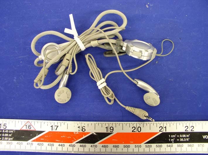
RXSC570
May 05, 2004GSM/GPRS 1900 MHz Mobile Phone
Equipment Class
PCE - PCS Licensed Transmitter held to ear