RYQ-NF2DATA CARD
FIH CO., LTD.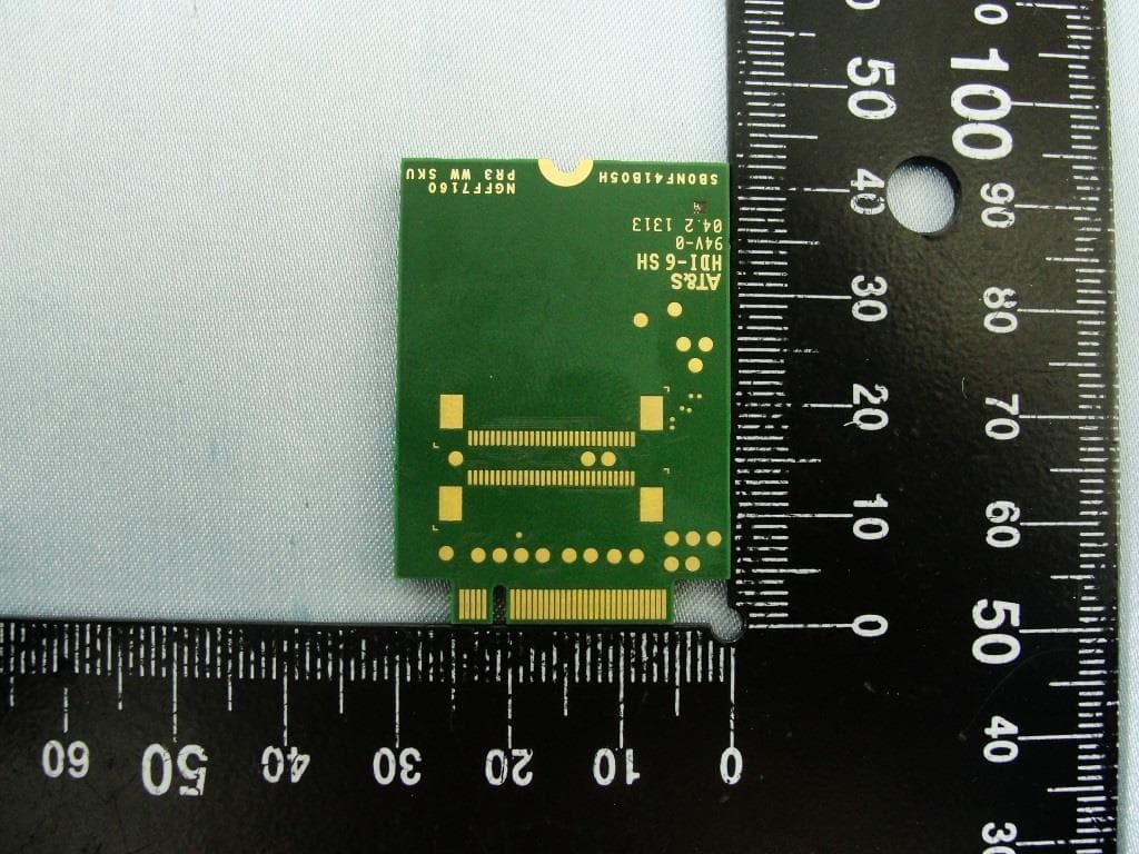
Click to zoom
Application Details
- Equipment Class
- PCB - PCS Licensed Transmitter
- Date of Grant
- Jul 24, 2013
- Application Purpose
- Original Equipment
- Date of Application
- Jul 23, 2013
- Equipment Note
- DATA CARD
- Frequency Range
- 709.00000000 - 711.00000000
- Company
- FIH CO., LTD.
- Country
- Taiwan
Documents & Files
Document Text
Text extracted from the exhibit documents filed with the FCC. Open a document above to read the original.
Users Manual
M.2 connector, embeded into Ultrabook or Pad device Quick Install Guide Module : NF4 WW 7160 (2G/3G/4G) data card 1. The Data Card connector (Pins) insert into NGFF connector (Femal)2. Plug 3G/4G diversity/GPS antenna’s cable to system connector.3. Plug 2G/3G/4G antenna’s cable to system connector.4. Fixing Data card in System. Connect to 2G/3G/4G diversityand GPS antenna Connect to 2G/3G/4G antenna
Users Manual
Manual Information to the End User The OEM integrator has to be aware not to provide information to the end user regarding how to install or remove this RF module in the user’s manual of the end product which integrates this module. The end user manual shall include all required regulatory information/warning as show in this manual. Federal Communication Commission Interference Statement This device complies with Part 15 of the FCC Rules. Operation is subject to the following two conditions: (1) This device may not cause harmful interference, and (2) this device must accept any interference received, including interference that may cause undesired operation. This equipment has been tested and found to comply with the limits for a Class B digital device, pursuant to Part 15 of the FCC Rules. These limits are designed to provide reasonable protection against harmful interference in a residential installation. This equipment generates, uses and can radiate radio frequency energy and, if not installed and used in accordance with the instructions, may cause harmful interference to radio communications. However, there is no guarantee that interference will not occur in a particular installation. If this equipment does cause harmful interference to radio or television reception, which can be determined by turning the equipment off and on, the user is encouraged to try to correct the interference by one of the following measures: ‐ Reorient or relocate the receiving antenna. ‐ Increase the separation between the equipment and receiver. ‐ Connect the equipment into an outlet on a circuit different from that to which the receiver is connected. ‐ Consult the dealer or an experienced radio/TV technician for help. Any changes or modifications not expressly approved by the party responsible for compliance could void the user's authority to operate this equipment. This transmitter must not be co‐located or operating in conjunction with any other antenna or transmitter. Industry Canada Statement This device complies with Industry Canada license‐exempt RSS standard(s). Operation is subject to the following two conditions: (1) this device may not cause interference, and (2) this device must accept any interference, including interference that may cause undesired operation of the device. Le présent appareil est conforme aux CNR d'Industrie Canada applicables aux appareils radio exempts de licence. L'exploitation est autorisée aux deux conditions suivantes: (1) l'appareil ne doit pas produire de brouillage, et (2) l'utilisateur de l'appareil doit accepter tout brouillage radioélectrique subi, même si le brouillage est susceptible d'en compromettre le fonctionnement." CAN ICES-3(B)/ NMB-3(B) Radiation Exposure Statement This equipment complies with FCC/IC radiation exposure limits set forth for an uncontrolled environment. This equipment should be installed and operated with minimum distance 20 cm between the radiator & your body. End Product Labeling When the module is installed in the host device, the FCC ID label must be visible through a window on the final device or it must be visible when an access panel, door or cover is easily re‐moved. If not, a second label must be placed on the outside of the final device that contains the following text: “Contains FCC ID: RYQ‐NF2” "Contains IC: 6719C‐NF2" The grantee's FCC ID/IC ID can be used only when all FCC/IC compliance requirements are met. This device is intended only for OEM integrators under the following conditions: (1) The antenna must be installed such that 20 cm is maintained between the antenna and users, (2) The transmitter module may not be co‐located with any other transmitter or antenna. (3) To comply with FCC/IC regulations limiting both maximum RF output power and human exposure to RF radiation, the maximum antenna gain including cable loss in a mobile exposure condition must not exceed: 。 5.0 dBi in Cellular band 。 3.0 dBi in PCS band 。 5.5 dBi in AWS band 。 5.0 dBi in 700 MHz band In the event that these conditions cannot be met (for example certain laptop configurations or co‐location with another transmitter), then the FCC/IC authorization is no longer considered valid and the FCC ID/IC ID cannot be used on the final product. In these circumstances, the OEM integrator will be responsible for re‐evaluating the end product (including the transmitter) and obtaining a separate FCC/IC authorization.
Cover Letter(s)
Rev. 1/1/03 Foxconn International Holdings Ltd. No.4, Mingsheng St., Tu-Cheng Dist., New Taipei City 23679, Taiwan Tel: +886-2-2268-5511 ; Fax: +886-2-2269-2922 Date: July 3, 2013 Federal Communications Commission Authorization and Evaluation Division Permanent Confidentiality Request regarding application for certification of FCC ID: RYQ-NF2 Pursuant to Sections 0.457 and 0.459 of the Commission’s Rules, we hereby request Permanent Confidential treatment of information accompanying this application as outlined below: Schematics Block Diagram Parts List Operation Description Tune up Procedure The above materials contain trade secrets and proprietary information not customarily released to the public. The public disclosure of these materials may be harmful to the applicant and provide unjustified benefits to its competitors. Sincerely, ________________________ Tom Hsu
Cover Letter(s)
1/1 Foxconn International Holdings Ltd. No.4, Mingsheng St., Tu-Cheng Dist., New Taipei City 23679, Taiwan Tel: +886-2-2268-5511 ; Fax: +886-2-2269-2922 Date: July 3, 2013 Federal Communications Commission Authorization and Evaluation Division RE : Certification Application FCC ID : RYQ-NF2 To Whom It May Concern, Pursuant to sections 0.457 and 0.459 of CFR 47 and to avoid premature release of sensitive information prior to marketing or release of the product to the public, the applicant requests the following documents contained in this certification application be temporarily withheld from public disclosure for an initial period of 180 days: External Photos Internal Photos Test Setup Photos User Manual The application contains technical information, which Foxconn International Holdings Ltd. deems to be trade secrets and proprietary. If made public, the information might be used to the disadvantage of the applicant in the market place. Sincerely, Tom Hsu
Cover Letter(s)
Foxconn International Holdings Ltd. No.4, Mingsheng St., Tu-Cheng Dist., New Taipei City 23679, Taiwan, R.O.C. Date: July 22, 2013 Modular Approval Check list FCC ID: RYQ-NF2 Item Requirements EUT 1. The modular transmitter must have its own RF shielding. The module is equipped with its own shielding case. 2. The modular transmitter must have buffered modulation / data inputs. The module has buffer modulation / data inputs. 3. The modular transmitter must have its own power supply regulation. The module has its own power supply regulation. 4. The module must contain a permanently attached antenna, or contain a unique antenna connector, and be marketed and operated only with specific antenna(s), Not applicable to licensed modules 5. The modular transmitter must be tested in a stand-alone configuration. EUT conformance testing was performed in a standalone configuration. 6. The modular transmitter must be labeled with its own FCC ID number. The module transmitter will be labeled with its own FCC ID, and for OEM integration the integration manual contains labeling instructions for the host device per Part 15.212 (vi) 7. The modular transmitter must comply with any specific rule or operating requirements applicable to the transmitter and the manufacturer must provide adequate instructions along with the module to explain any such requirements. The module approved transmitter complies with all applicable rules and the integration manual contains any specific requirements addressed to the integrator and/or to the end-user of the final end-product. 8. The modular transmitter must comply with any applicable RF exposure requirement. Compliance with RF exposure requirement is addressed in RF exposure report.
Cover Letter(s)
The correction was made on page 116 and page 182 to 197. Today we additionally add the explanation in page 117 to address the limit -25 dBm in page 182 to 197, please use attached report instead. Page 116 Page 117 Page 182 to 197:
External Photos
Photographs of EUT Report No.: EP352141 Brand Name: AMBIT / Model Name: NF2 / Marketing Name: M.2 module SPORTON INTERNATIONAL INC. Page Number : 1 of 5 TEL : 886-3-327-3456 Report Issued Date : Jul. 23, 2013 FAX : 886-3-328-4978 Report Version : Rev. 01 FCC ID : RYQ-NF2 IC : 6719C-NF2 720510 1. External Photograph of EUT Photographs of EUT Report No.: EP352141 Brand Name: AMBIT / Model Name: NF2 / Marketing Name: M.2 module SPORTON INTERNATIONAL INC. Page Number : 2 of 5 TEL : 886-3-327-3456 Report Issued Date : Jul. 23, 2013 FAX : 886-3-328-4978 Report Version : Rev. 01 FCC ID : RYQ-NF2 IC : 6719C-NF2 720510
ID Label/Location Info
Front of the module Shield Label Location
ID Label/Location Info
NF4 WW (7160) –Label Brand: AMBIT Model Name: NF2
Internal Photos
Photographs of EUT Report No.: EP352141 Brand Name: AMBIT / Model Name: NF2 / Marketing Name: M.2 module SPORTON INTERNATIONAL INC. Page Number : 3 of 5 TEL : 886-3-327-3456 Report Issued Date : Jul. 23, 2013 FAX : 886-3-328-4978 Report Version : Rev. 01 FCC ID : RYQ-NF2 IC : 6719C-NF2 720510 2. Internal Photograph of EUT Photographs of EUT Report No.: EP352141 Brand Name: AMBIT / Model Name: NF2 / Marketing Name: M.2 module SPORTON INTERNATIONAL INC. Page Number : 4 of 5 TEL : 886-3-327-3456 Report Issued Date : Jul. 23, 2013 FAX : 886-3-328-4978 Report Version : Rev. 01 FCC ID : RYQ-NF2 IC : 6719C-NF2 Photographs of EUT Report No.: EP352141 Brand Name: AMBIT / Model Name: NF2 / Marketing Name: M.2 module SPORTON INTERNATIONAL INC. Page Number : 5 of 5 TEL : 886-3-327-3456 Report Issued Date : Jul. 23, 2013 FAX : 886-3-328-4978 Report Version : Rev. 01 FCC ID : RYQ-NF2 IC : 6719C-NF2
RF Exposure Info
SPORTON INTERNATIONAL INC. Page Number : 1 of 27 TEL : 886-3-327-3456 Report Issued Date : Jul. 22, 2013 FAX : 886-3-328-4978 Report Version : Rev. 01 FCC ID : RYQ-NF2 RF Exposure Evaluation Report Report No. : FA352141 RF Exposure Evaluation Report APPLICANT : Foxconn International Holdings Ltd. EQUIPMENT : Data Card BRAND NAME : AMBIT MODEL NAME : NF2 MARKETING NAME M.2 module FCC ID : RYQ-NF2 STANDARD : 47 CFR Part 2.1091 We, SPORTON INTERNATIONAL INC., would like to declare that the device has been evaluated in accordance with 47 CFR Part 2.1091, and pass the limit. Without written approval of SPORTON INTERNATIONAL INC., the test report shall not be reproduced except in full. SPORTON INTERNATIONAL INC. No. 52, Hwa Ya 1 st Rd., Hwa Ya Technology Park, Kwei-Shan Hsiang, Tao Yuan Hsien, Taiwan, R.O.C. Approved by: Jones Tsai / Manager Reviewed by: Eric Huang / Deputy Manager SPORTON INTERNATIONAL INC. Page Number : 2 of 27 TEL : 886-3-327-3456 Report Issued Date : Jul. 22, 2013 FAX : 886-3-328-4978 Report Version : Rev. 01 FCC ID : RYQ-NF2 RF Exposure Evaluation Report Report No. : FA352141 Table of Contents 1. ADMINISTRATION DATA ........................................................................................................................... 4 1.1. Testing Laboratory ............................................................................................................................. 4 1.2. Applicant ............................................................................................................................................ 4 1.3. Manufacturer ...................................................................................................................................... 4 2. DESCRIPTION OF EQUIPMENT UNDER TEST (EUT) ............................................................................. 5 3. RF EXPOSURE LIMIT INTRODUCTION .................................................................................................... 6 4. MAXIMUM RF AVERAGE OUTPUT POWER AMONG PRODUCTION UNITS ........................................ 7 5. CONDUCTED RF OUTPUT POWER (UNIT: DBM) .................................................................................. 14 6. RADIO FREQUENCY RADIATION EXPOSURE EVALUATION ............................................................. 26 SPORTON INTERNATIONAL INC. Page Number : 3 of 27 TEL : 886-3-327-3456 Report Issued Date : Jul. 22, 2013 FAX : 886-3-328-4978 Report Version : Rev. 01 FCC ID : RYQ-NF2 RF Exposure Evaluation Report Report No. : FA352141 Revision History REPORT NO. VERSION DESCRIPTION ISSUED DATE FA352141 Rev. 01 Initial issue of report Jul. 22, 2013 SPORTON INTERNATIONAL INC. Page Number : 4 of 27 TEL : 886-3-327-3456 Report Issued Date : Jul. 22, 2013 FAX : 886-3-328-4978 Report Version : Rev. 01 FCC ID : RYQ-NF2 RF Exposure Evaluation Report Report No. : FA352141 1. Administration Data 1.1. Testing Laboratory Test Site SPORTON INTERNATIONAL INC. Test Site Location No. 52, Hwa Ya 1 st Rd., Hwa Ya Technology Park, Kwei-Shan Hsiang, Tao Yuan Hsien, Taiwan, R.O.C. TEL: +886-3-327-3456 FAX: +886-3-328-4978 1.2. Applicant Company Name Foxconn International Holdings Ltd. Address No. 4, Mingsheng St., Tu-Cheng Dist., New Taipei City 23679, Taiwan 1.3. Manufacturer Company Name Foxconn International Holdings Ltd. Address No. 4, Mingsheng St.,Tu-Cheng Dist., New Taipei City 23679, Taiwan SPORTON INTERNATIONAL INC. Page Number : 5 of 27 TEL : 886-3-327-3456 Report Issued Date : Jul. 22, 2013 FAX : 886-3-328-4978 Report Version : Rev. 01 FCC ID : RYQ-NF2 RF Exposure Evaluation Report Report No. : FA352141 2. Description of Equipment Under Test (EUT) Product Feature & Specification EUT Type Data Card Brand Name AMBIT Model Name NF2 Marketing Name M.2 module FCC ID RYQ-NF2 Wireless Technology and Frequency Range GSM850: 824.2 MHz ~ 848.8 MHz GSM1900: 1850.2 MHz ~ 1909.8 MHz WCDMA Band V: 826.4 MHz ~ 846.6 MHz WCDMA Band IV: 1712.4 MHz ~ 1752.6 MHz WCDMA Band II: 1852.4 MHz ~ 1907.6 MHz LTE Band 17: 706.5 MHz ~ 713.5 MHz LTE Band 13: 779.5 MHz ~ 784.5 MHz LTE Band 5: 824.7 MHz ~ 848.3 MHz LTE Band 4: 1710.7 MHz ~ 1754.3 MHz LTE Band 2: 1850.7 MHz ~ 1909.3 MHz LTE Band 7: 2506.5 MHz ~ 2535 MHz and 2553.5 MHz ~ 2570MHz Mode •GPRS/EGPRS •UMTS Rel 99 •HSDPA Rel 7, Cat14 •DC-HSDPA Rel 8, Cat24 •HSUPA Rel 6, Cat6 •LTE: QPSK, 16QAM HW Version PR3.2 SW Version FIH7160_MODEM_01.1326.00 EUT Stage Production Unit Remark: The above EUT's information was declared by manufacturer. Please refer to the specifications or user's manual for more detailed description. SPORTON INTERNATIONAL INC. Page Number : 6 of 27 TEL : 886-3-327-3456 Report Issued Date : Jul. 22, 2013 FAX : 886-3-328-4978 Report Version : Rev. 01 FCC ID : RYQ-NF2 RF Exposure Evaluation Report Report No. : FA352141 3. RF Exposure Limit Introduction The FCC categorizes the RF exposure limit based on the intended usage of the device and the user’s awareness and ability to exercise control over his or her exposure. This is a consumer product to be used in the home, hence this device was evaluated by mobile device with general population/uncontrolled exposure condition. The definition of these category are shown as follows: Mobile Devices: A mobile device is defined as a transmitting device designed to be used in other than fixed locations and to be generally used in such a way that a separation distance of at least 20 centimeters is normally maintained between the transmitters' radiating structures and the body of the user or nearby persons. Transmitters designed to be used by consumers or workers that can be easily re-located are considered mobile devices if they meet the 20 centimeter separation requirement. The FCC rules for evaluating mobile devices for RF compliance are found in 47 CFR 2.1091. General Population/Uncontrolled Exposure: The general population / uncontrolled exposure limits are applicable to situations in which the general public may be exposed or i…
Text truncated - open the document above for the full version.
Test Report
SPORTON INTERNATIONAL INC. Page Number : 1 of 111 TEL : 886-3-327-3456 Report Issued Date : Jul. 23, 2013 FAX : 886-3-328-4978 Report Version : Rev. 01 FCC ID : RYQ-NF2 FCC RF Test Report Report No. : FG352141A FCC RF Test Report APPLICANT : Foxconn International Holdings Ltd. EQUIPMENT : Data Card BRAND NAME : AMBIT MODEL NAME : NF2 MARKETING NAME : M.2 module FCC ID : RYQ-NF2 STANDARD : FCC 47 CFR Part 2, 22(H), 24(E), 27(L) CLASSIFICATION : PCS Licensed Transmitter (PCB) The product was received on May 21, 2013 and completely tested on Jun. 10, 2013. We, SPORTON INTERNATIONAL INC., would like to declare that the tested sample has been evaluated in accordance with the procedures given in ANSI / TIA / EIA-603-C-2004 and shown compliance with the applicable technical standards. The test results in this report apply exclusively to the tested model / sample. Without written approval of SPORTON INTERNATIONAL INC., the test report shall not be reproduced except in full. Reviewed by: Joseph Lin / Supervisor Approved by: Jones Tsai / Manager SPORTON INTERNATIONAL INC. No. 52, Hwa Ya 1 st Rd., Hwa Ya Technology Park, Kwei-Shan Hsiang, Tao Yuan Hsien, Taiwan, R.O.C. SPORTON INTERNATIONAL INC. Page Number : 2 of 111 TEL : 886-3-327-3456 Report Issued Date : Jul. 23, 2013 FAX : 886-3-328-4978 Report Version : Rev. 01 FCC ID : RYQ-NF2 FCC RF Test Report Report No. : FG352141A TABLE OF CONTENTS REVISION HISTORY .......................................................................................................................................... 3 SUMMARY OF TEST RESULT ......................................................................................................................... 4 1 GENERAL DESCRIPTION .......................................................................................................................... 5 1.1 Applicant ............................................................................................................................................ 5 1.2 Manufacturer ..................................................................................................................................... 5 1.3 Feature of Equipment Under Test ..................................................................................................... 5 1.4 Product Specification of Equipment Under Test ............................................................................... 6 1.5 Modification of EUT ........................................................................................................................... 6 1.6 Frequency Tolerance, and Emission Designator .............................................................................. 7 1.7 Testing Site........................................................................................................................................ 7 1.8 Applied Standards ............................................................................................................................. 8 2 TEST CONFIGURATION OF EQUIPMENT UNDER TEST ........................................................................ 9 2.1 Test Mode.......................................................................................................................................... 9 2.2 Connection Diagram of Test System .............................................................................................. 11 2.3 Support Unit used in test configuration and system ........................................................................ 11 2.4 Measurement Results Explanation Example .................................................................................. 12 3 TEST RESULT ........................................................................................................................................... 13 3.1 Conducted Output Power Measurement ......................................................................................... 13 3.2 Peak-to-Average Ratio .................................................................................................................... 15 3.3 Occupied Bandwidth and 26dB Bandwidth Measurement .............................................................. 31 3.4 Band Edge Measurement ................................................................................................................ 55 3.5 Conducted Spurious Emission Measurement ................................................................................. 70 3.6 Field Strength of Spurious Radiation Measurement ....................................................................... 89 3.7 Frequency Stability Measurement ................................................................................................. 105 4 LIST OF MEASURING EQUIPMENTS.................................................................................................... 110 5 UNCERTAINTY OF EVALUATION ......................................................................................................... 111 APPENDIX A. PHOTOGRAPHS OF EUT APPENDIX B. SETUP PHOTOGRAPHS SPORTON INTERNATIONAL INC. Page Number : 3 of 111 TEL : 886-3-327-3456 Report Issued Date : Jul. 23, 2013 FAX : 886-3-328-4978 Report Version : Rev. 01 FCC ID : RYQ-NF2 FCC RF Test Report Report No. : FG352141A REVISION HISTORY REPORT NO. VERSION DESCRIPTION ISSUED DATE FG352141A Rev. 01 Initial issue of report Jul. 23, 2013 SPORTON INTERNATIONAL INC. Page Number : 4 of 111 TEL : 886-3-327-3456 Report Issued Date : Jul. 23, 2013 FAX : 886-3-328-4978 Report Version : Rev. 01 FCC ID : RYQ-NF2 FCC RF Test Report Report No. : FG352141A SUMMARY OF TEST RESULT Report Section FCC Rule IC Rule Description Limit Result Remark 3.1 §2.1046 RSS-132 (5.4) RSS-133 (6.4) RSS-139 (6.4) Conducted Output Power Reporting Only PASS - 3.2 §24.232(d) §27.50(d)(5) RSS-132 (5.4) RSS-133(6.4) RSS-139 (6.4) Peak-to-Average Ratio < 13 dB PASS - 3.3 §2.1049 §22.917(a) §24.238(b) §27.53(g) RSS-…
Text truncated - open the document above for the full version.
Test Report
SPORTON INTERNATIONAL INC. Page Number : 1 of 425 TEL : 886-3-327-3456 Report Issued Date : Aug. 14, 2013 FAX : 886-3-328-4978 Report Version : Rev. 02 FCC ID : RYQ-NF2 FCC RF Test Report Report No. : FG352141B FCC RF Test Report APPLICANT : Foxconn International Holdings Ltd. EQUIPMENT : Data Card BRAND NAME : AMBIT MODEL NAME : NF2 MARKETING NAME : M.2 module FCC ID : RYQ-NF2 STANDARD : 47 CFR Part 2, 22(H), 24(E), 27 CLASSIFICATION : PCS Licensed Transmitter (PCB) The product was received on May 21, 2013 and completely tested on Jun. 27, 2013. We, SPORTON INTERNATIONAL INC., would like to declare that the tested sample has been evaluated in accordance with the procedures given in ANSI / TIA / EIA-603-C-2004 and shown compliance with the applicable technical standards. The test results in this report apply exclusively to the tested model / sample. Without written approval of SPORTON INTERNATIONAL INC., the test report shall not be reproduced except in full. Reviewed by: Joseph Lin / Supervisor Approved by: Jones Tsai / Manager SPORTON INTERNATIONAL INC. No. 52, Hwa Ya 1 st Rd., Hwa Ya Technology Park, Kwei-Shan Hsiang, Tao Yuan Hsien, Taiwan, R.O.C. SPORTON INTERNATIONAL INC. Page Number : 2 of 425 TEL : 886-3-327-3456 Report Issued Date : Aug. 14, 2013 FAX : 886-3-328-4978 Report Version : Rev. 02 FCC ID : RYQ-NF2 FCC RF Test Report Report No. : FG352141B TABLE OF CONTENTS REVISION HISTORY .......................................................................................................................................... 3 SUMMARY OF TEST RESULT ......................................................................................................................... 4 1 GENERAL DESCRIPTION .......................................................................................................................... 6 1.1 Applicant ............................................................................................................................................ 6 1.2 Manufacturer ...................................................................................................................................... 6 1.3 Feature of Equipment Under Test ..................................................................................................... 6 1.4 Product Specification of Equipment Under Test ................................................................................ 7 1.5 Modification of EUT ........................................................................................................................... 7 1.6 Emission Designator .......................................................................................................................... 8 1.7 Testing Site ...................................................................................................................................... 10 1.8 Applied Standards ........................................................................................................................... 10 2 TEST CONFIGURATION OF EQUIPMENT UNDER TEST ...................................................................... 11 2.1 Test Mode ........................................................................................................................................ 11 2.2 Connection Diagram of Test System ............................................................................................... 13 2.3 Support Unit used in test configuration and system ........................................................................ 14 2.4 Measurement Results Explanation Example ................................................................................... 14 3 TEST RESULT ........................................................................................................................................... 15 3.1 Conducted Output Power Measurement ......................................................................................... 15 3.2 Peak-to-Average Ratio .................................................................................................................... 40 3.3 Occupied Bandwidth ........................................................................................................................ 67 3.4 Conducted Band Edge Measurement ........................................................................................... 116 3.5 Conducted Spurious Emission Measurement ............................................................................... 214 3.6 Radiated Spurious Emission Measurement .................................................................................. 354 3.7 Frequency Stability Measurement ................................................................................................. 405 4 LIST OF MEASURING EQUIPMENTS.................................................................................................... 424 5 UNCERTAINTY OF EVALUATION ......................................................................................................... 425 APPENDIX A. PHOTOGRAPHS OF EUT APPENDIX B. SETUP PHOTOGRAPHS SPORTON INTERNATIONAL INC. Page Number : 3 of 425 TEL : 886-3-327-3456 Report Issued Date : Aug. 14, 2013 FAX : 886-3-328-4978 Report Version : Rev. 02 FCC ID : RYQ-NF2 FCC RF Test Report Report No. : FG352141B REVISION HISTORY REPORT NO. VERSION DESCRIPTION ISSUED DATE FG352141B Rev. 01 Initial issue of report Jul. 23, 2013 FG352141B Rev. 02 Added description of section 3.4 for Part 27.52(m) Aug. 14, 2013 SPORTON INTERNATIONAL INC. Page Number : 4 of 425 TEL : 886-3-327-3456 Report Issued Date : Aug. 14, 2013 FAX : 886-3-328-4978 Report Version : Rev. 02 FCC ID : RYQ-NF2 FCC RF Test Report Report No. : FG352141B SUMMARY OF TEST RESULT Report Section FCC Rule IC Rule Description Limit Result Remark 3.1 §2.1046 RSS-132 (5.4) RSS -133 (6.4) RSS -139(6.4) Conducted Output Power Reporting Only PASS - 3.2 §24.232(d) 27.53(d)(5) RSS-133(6.4…
Text truncated - open the document above for the full version.
Test Report
SPORTON INTERNATIONAL INC. Page Number : 214 of 425 TEL : 886-3-327-3456 Report Issued Date : Aug. 14, 2013 FAX : 886-3-328-4978 Report Version : Rev. 02 FCC ID : RYQ-NF2 FCC RF Test Report Report No. : FG352141B 3.5 Conducted Spurious Emission Measurement 3.5.1 Description of Conducted Spurious Emission Measurement For Band 2, 4, 5, 13, 17 The power of any emission outside of the authorized operating frequency ranges must be lower than the transmitter power (P) by a factor of at least 43 + 10 log (P) dB. For Band 7 The power of any emission outside of the authorized operating frequency ranges must be lower than the transmitter power (P) by a factor of at least 55 + 10 log (P) dB. It is measured by means of a calibrated spectrum analyzer and scanned from 9 kHz up to a frequency including its 10 th harmonic. 3.5.2 Measuring Instruments See list of measuring instruments of this test report. SPORTON INTERNATIONAL INC. Page Number : 215 of 425 TEL : 886-3-327-3456 Report Issued Date : Aug. 14, 2013 FAX : 886-3-328-4978 Report Version : Rev. 02 FCC ID : RYQ-NF2 FCC RF Test Report Report No. : FG352141B 3.5.3 Test Procedures 1. The EUT was connected to spectrum analyzer and base station via power divider. 2. The RF output of EUT was connected to the spectrum analyzer by RF cable and attenuator. The path loss was compensated to the results for each measurement. 3. The middle channel for the highest RF power within the transmitting frequency was measured. 4. The conducted spurious emission for the whole frequency range was taken. 5. Make the measurement with the spectrum analyzer's RBW = 1MHz, VBW = 3MHz, taking the record of maximum spurious emission. 6. The RF fundamental frequency should be excluded against the limit line …
Text truncated - open the document above for the full version.
Contact Information
Applicant
Barry Tsai(Manager)
Test Firm
Sporton International Inc.Alex Chen
Technical Specifications
| # | Rule Parts | Frequency Range | Power Output | Emission | Tolerance |
|---|---|---|---|---|---|
| 55 | 27 | 709 MHz - 711 MHz | 189.70 mW | 9M10D7W | 0.008 ppm |
Other Applications from FIH CO., LTD.
RYQFPLX26
Apr 08, 2026Gizmo Watch 4
Equipment Class
CXX - Communications Rcvr for use w/ licensed Tx and CBsRYQGW4
Apr 02, 2026Smartwatch
Equipment Class
TNT - Licensed Non-Broadcast Transmitter Worn on BodyRYQ31PHBM2000A
Jul 29, 20244G Module
Equipment Class
PCB - PCS Licensed Transmitter
RYQGP3
Nov 30, 2023LTE smartphone
Equipment Class
DSS - Part 15 Spread Spectrum Transmitter
RYQGW23
Aug 06, 2023Smartwatch
Equipment Class
JBP - Part 15 Class B Computing Device Peripheral