RZ6SW-1500NLCD Monitor
SKD LCD Co., Ltd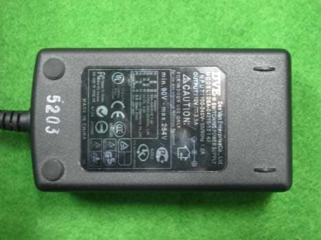
Click to zoom
Application Details
- Equipment Class
- JBP - Part 15 Class B Computing Device Peripheral
- Date of Grant
- Apr 25, 2004
- Application Purpose
- Original Equipment
- Date of Application
- Apr 25, 2004
- Equipment Note
- LCD Monitor
- Company
- SKD LCD Co., Ltd
- Country
- South Korea
Documents & Files
Document Text
Text extracted from the exhibit documents filed with the FCC. Open a document above to read the original.
Users Manual
USER’S MANUAL TFT LCD Monitor ‘cozy’and ‘eye’LCD Monitor This user’s manual has been provided for your safety. You can prevent serious electrical shock and hazards by keeping in mind the following : Safety instructions 1. Before connecting the AC power cord to the DC adapter outlet,make sure the voltage designation of the DC adapter corresponds to the local electrical supply. 2. Never insert anything metallic into the cabinet openings of the Liquid Crystal Display (LCD) monitor; doing so may create the danger of electric shock. 3. To avoid electric shock, never touch the inside of the LCD monitor. Only a qualified technician should open the case of the LCD monitor. TFT LCD MONITOR 4. Never use your LCD monitor if the power cord has been damaged. Do not allow anything to rest on the power cord, and keep thecord away from areas where people can trip over it. 5. Be sure to hold the plug, not the cord, when disconnecting the LCD monitor from an electric socket. 6. Openings in the LCD monitor cabinet are provided for ventilation. To prevent overheating, these openings should not be blockedor covered. Also, avoid using the LCD monitor on a bed, sofa, rug or other soft surface. Doing so may block the ventilation openings in the bottom ofthe cabinet. If you put the LCD monitor in a bookcase or some other enclosed space, be sure to provide adequate ventilation. WARNING Safety instructions 1. Put your LCD monitor in a location with low humidity and a minimum amount of dust. 2. Do not expose the LCD monitor to rain or use it near water. (in kitchens, near swimming pools, etc.) If the LCD monitoraccidentally gets wet, unplug it and contact an authorized dealer immediately. You can clean the LCD monitor with a damp cloth when necessary, but be sure to unplug the LCD monitor first. 3. Place the LCD monitor on a solid surface and treat it carefully. The screen is made of thin glass with a plastic front surface and can be damaged if dropped, hit or scratched. Do not clean the front panelwithketone-type materials (e.g., acetone), Ethyl alcohol, toluene, Ethyl acid, Methyl or Chloride –these may damage the panel. 4. Position your LCD monitor near an easily accessible AC outlet. 5. If your monitor does not operate normally –in particular, if there are any unusual sounds or smells coming from it –unplug it immediately and contact an authorized dealer or service center. 6. High temperature can cause problems. Don’t use your LCD monitor in direct sunlight and keep it away from fireplaces, and other sources of heat. 7. Unplug the LCD monitor when it is going to be left unused foran extended period of time. 8. Unplug your LCD monitor from the AC outlet before any service. TFT LCD MONITOR This user’s manual has been provided for your safety. You can prevent serious electrical shock and hazards by keeping in mind thefollowing: CAUTION Contents TFT LCD MONITOR Safety instructions Warning Caution Before installation Characteristics Contents Connecting a PC Assembling Monitor Pin Assignment Operation Control for the OSD (On Screen Display) Picture Setting Image Setting OSD settings Color Setting Resolution & Frequency Troubleshooting Attention Regarding panel display Instructions for safety Specification Specification 1 1 1 4 5 6 7 11 11 12 10 8 Troubleshooting 2 3 9 TFT LCD MONITOR 1 Characteristics •Automatically adjusts settings for optical viewing during setup. •Including power saving mode -VESA DPMS •HALF TONE OSD (On Screen Display) function Connecting a PC Warning When connecting the monitor to a PC, be certain the power switch is in the “off”position. This minimizes the risk of electric shock or malfunction. Caution Improperly connecting the video cable with the monitor may result in a malfunction. Please verify the method prior to connecting. For setting up the monitor Turn off your computer and monitor. Connect a PC D-Sub (VGA) Cable between your PC and VGA of the monitor. And then fasten the screws on both sides of the cable. Connect a DC Power cable to the power input jack of the monitor. Before installation Contents TFT LCD MONITOR 2 Assembling Monitor •First, properly align the hinge and the hinge hole which is located on the lower back side of the monitor. •Second, once the hinge and hinge hole are properly aligned, gently push the hinge into the hinge hole by pressing down from the top of the monitor, making certain that the hinge and stand are firm in their positions. •Third, continue to push on the top of the monitor until the hinge locks into the monitor. Warning When assembling and disassembling the monitor, take all precautions to avert physical injury. Pressing too hard on the monitor can also damage the unit. Caution When assembling the monitor, avoid pressing too hard on the monitor as it can damage the unit. •Avoid disassembling the monitor and monitor stand once they have been connected Before installation 3 •GND•Shell •DDC-SCL•15 •V-Sync•14 •H-Sync•13 •DDC-SDA•12 •GND•11 •Sync GND•10 •No Connection•9 •Blue GND•8 •Green GND•7 •Red GND•6 •DDC GND•5 •GND•4 •Blue•3 •Green•2 •Red•1 •Name•Pin TFT LCD MONITOR Pin Assignment of 15 Pin D-sub Connector Before installation Pin Assignment TFT LCD MONITOR 4 Operation OSD control buttons UP button Move to increaseitem and decrease the value of the selected item. Hot Key : Without pressing the menu button, you can control “Brightness”with the “UP”button. Control for the OSD (On Screen Display) MENU button OSD Menu on/off SEL(Select) button Select a command function and return to menu Hot Key : Without pressing the menu button, you can operate “Auto setup”with the “SEL”button DOWN button Move to previous item and decrease the value of the selected item. Hot Key : Without pressing the menu button, you can control “Contrast”with the “DOWN”button. Power LED When power is on, the light is working Green : Monitor Power ON OFF : Monitor Power OFF Orange : power Save Mode Power switch LCD monitor power on/off TFT LCD MONITOR 5 Operation PictureSettings Brightnes…
Text truncated - open the document above for the full version.
External Photos
KTI04EF04006 FCC ID: RZ6SW-1500N Korea Technology Institute Co., Ltd. Page 1 of 4 External photo (front) KTI04EF04006 FCC ID: RZ6SW-1500N Korea Technology Institute Co., Ltd. Page 2 of 4 External photo (Rear) KTI04EF04006 FCC ID: RZ6SW-1500N Korea Technology Institute Co., Ltd. Page 3 of 4 External photo (Adaptor) KTI04EF04006 FCC ID: RZ6SW-1500N Korea Technology Institute Co., Ltd. Page 4 of 4 External photo (Adaptor)
ID Label/Location Info
KTI04EF04006 FCC ID: RZ6SW-1500N Korea Technology Institute Co., Ltd. Page 1 of 1 FCC ID Sample Label Model Number: SW-1500N FCC ID: RZ6SW-1500N S/N: SKD LCD Co., Ltd. Made in Korea This device complies with part 15 of the FCC Rules. Operation is subject to the following two conditions: (1)This device may not cause harmful interference, and (2)This device must accept any interference received, including interference that may cause undesired operation.
ID Label/Location Info
KTI04EF04006 FCC ID: RZ6SW-1500N Korea Technology Institute Co., Ltd. Page 1 of 1 Label location FCC Label Location
Internal Photos
KTI04EF04006 FCC ID: RZ6SW-1500N Korea Technology Institute Co., Ltd. Page 1 of 6 Internal photo (Front) KTI04EF04006 FCC ID: RZ6SW-1500N Korea Technology Institute Co., Ltd. Page 2 of 6 Internal photo (Rear) KTI04EF04006 FCC ID: RZ6SW-1500N Korea Technology Institute Co., Ltd. Page 3 of 6 Internal photo (Front) KTI04EF04006 FCC ID: RZ6SW-1500N Korea Technology Institute Co., Ltd. Page 4 of 6 Internal photo (Rear) KTI04EF04006 FCC ID: RZ6SW-1500N Korea Technology Institute Co., Ltd. Page 5 of 6 Internal photo (Front) KTI04EF04006 FCC ID: RZ6SW-1500N Korea Technology Institute Co., Ltd. Page 6 of 6 Internal photo (Rear)
Test Report
KTI04EF04006 FCC ID: RZ6SW-1500N Korea Technology Institute Co., Ltd. Page 1 of 13 Test Report Test Report No.: KTI04EF04006 Registration No.: 99058 Applicant: SKD LCD Co., Ltd. Applicant Address: 2FL, Tae-sung B/D #238-77, Kasan-dong, Keumcheon-Gu, Seoul, Korea Product: LCD Monitor FCC ID: RZ6SW-1500N Model No. SW-1500N Receipt No.: 04-0320 Date of receipt:March 22, 2004 Date of Issue: April 19, 2004 Testing location Korea Technology Institute Co., Ltd. 51-19, Sanglim3-Ri, Docheok-Myeun, Gwangju-Shi, Gyeungki-Do, Korea Test Standards: FCC/ANSI. C63.4: 2001 Rule Parts: FCC Part 15, Class B Equipment Class: Computing Device Peripheral Test Result: The above-mentioned product has been tested with compliance. Tested by: E.S.Park / Engineer Approved by: G. C. Min /President Signature Date Signature Date Other Aspects: Abbreviations: OK, Pass=passed Fail=failed N/A=not applicable - This test report is not permitted to copy partly without our permission. - This test result is dependent on only equipment to be used. - This test result is based on a single evaluation of one sample of the above mentioned. - This test report must not be used by the client to claim product endorsement by NVLAP or any agency of the U.S Government. - We certify this test report has been based on the measurement standards that is traceable to the national or international standards. KTI04EF04006 FCC ID: RZ6SW-1500N Korea Technology Institute Co., Ltd. Page 2 of 13 Contents 1. 2. 3. 4. 5. 6. Annex1 Annex2 Contents List of Tables List of Figures List of Photographs General Test Site 2.1 Location 2.2 List of Test and Measurement Instruments 2.3 Test Data 2.4 Test Environment Description of the tested samples 3.1 Rating and Physical characteristics 3.2 Submitted documents Measurement conditions 4.1 Modes of operation 4.2 List of peripherals 4.3 Uncertainty 4.4 Test Setup Emission Test 5.1 Conducted Emissions 5.2 Radiated Emissions Photographs of the Test Set-up Label Photographs of EUT 2 2 2 2 3 3 3 4 4 4 5 5 5 6 6 6 6 7 8 8 12 14 16 18~20 List of Tables Table 1 List of test and measurement equipment Table 2 Test Data. Conducted Emissions Table 3 Test Data. Radiated Emissions List of Figures Figure 1 Spectral Diagram, LINE-PE Figure 2 Spectral Diagram, Neutral-PE List of Photographs Photograph 1 Setup for Radiated Emissions Photograph 2 Setup for Conducted Emissions 4 11 13 9 10 14 15 KTI04EF04006 FCC ID: RZ6SW-1500N Korea Technology Institute Co., Ltd. Page 3 of 13 1. General This equipment has been shown to be capable of compliance with the applicable technical standards and was tested in accordance with the measurement procedures as indicated in this report. We attest to the accuracy of data. Korea Technology Institute Co., Ltd. performed all measurements reported herein. And were made under Chief Engineer’s supervisor. We assume full responsibility for the completeness of these measurements and vouch for the qualifications of all persons taking them. 2. Test Site Korea Technology Institute Co., Ltd. 2.1 Location 51-19, Sanglim3-Ri, Docheok-Myeun, Gwangju-Shi, Gyeungki-Do, Korea The Test Site is in compliance with ANSI C63.4/2001 for measurement of radio Interference. KTI04EF04006 FCC ID: RZ6SW-1500N Korea Technology Institute Co., Ltd. Page 4 of 13 2.2 List of Test and Measurement Instruments Table 1: List of Test and Measurement Equipment Conducted Emissions Kind of Equipment Type S/N Calibrated until Spectrum Analyzer R3261C 61720417 11.2004 Field Strength Meter ESPC 832827/011 9.2004 LISN KNW407 8-1157-2 10.2004 LISN EM-7823 115019 4.2005 Conducted Cable N/A N/A 11.2004 - Radiated Emissions Kind of Equipment Type S/N Calibrated until Field Strength Meter ESPC 832827/011 9.2004 Spectrum Analyzer R3261C 61720417 11.2004 Pre Amplifier 8447D 2944A06874 11.2004 BiconiLog Antenna 3142B 1705 12.2004 Bilog Antenna CBL6140A 1217 5.2004 Open Site Cable N/A N/A 11.2004 Antenna Mast DETT-03 N/A N/A Antenna & Turntable controller DETT-04 91X519 N/A 2.3 Test Date Date of Application: March 22, 2004 Date of Test: April 7, 2004 2.4 Test Environment See each test item’s description. KTI04EF04006 FCC ID: RZ6SW-1500N Korea Technology Institute Co., Ltd. Page 5 of 13 3. Description of the tested samples The EUT is LCD Monitor. 3.1. Rating and Physical Characteristics Specification Viewing Size 15.0” Module Type Active Matrix TFT-LCD Dot Pitch 0.297mm x 0.297mm Viewing Angle U/D: 45/55, R/L : 65/65 Contrast Ratio 400:1 Luminance(cd/m 2 ) 250 cd/m 2 (Typ.) Resolution(MAX) 1024 x 768 @75Hz Display Color 16M colors Scanning Freq. : H 31KHz – 60KHz Scanning Freq. : V 56Hz – 75Hz Plug & Play VESA DDC1/2B User Control Brightness, Contrast, Autosetup, Language, Clock, H/V Position Halftone OSD, Phase, Auto color Control Surface treatment Hard Coating(3H) Anti-Glare Treatment Power Saving VESA DPMS standard Power Source 100V – 240V, DC 12V 3.5A Input Signal Analog R.G.B Input connector 15pin D-sub 3.2. Submitted Documents - User’s Guide - Block Diagram KTI04EF04006 FCC ID: RZ6SW-1500N Korea Technology Institute Co., Ltd. Page 6 of 13 4. Measurement Conditions Testing Input Voltage: AC 220V 4.1 Modes of Operation The EUT was in the following operation mode during all testing; 1) Display H pattern on monitor. 4.2 Additional Equipment DEVICE TYPE Manufacturer M/N S/N FCC ID PC Compaq computer Corp.ARMADA M7003J14FmpzBD2C - 4.3 Uncertainty 1) Radiated disturbance Uc (Combined standard Uncertainty) = 1.8dB Expanded uncertainty U=KUc K = 2 U = 3.6dB 2) Conducted disturbance Uc = 0.88dB U = KUc=2 x Uc = 1.8dB KTI04EF04006 FCC ID: RZ6SW-1500N Korea Technology Institute Co., Ltd. Page 7 of 13 4.4 Test Setup Signal Line Power Line EUT PC Printer MOUSE MOUSE Adaptor Keyboard KTI04EF04006 FCC ID: RZ6SW-1500N Korea Technology Institute Co., Ltd. Page 8 of 13 5. EMISSION Test 5.1.Conducted Emissions Result: Pass The line-conducted facility is located inside a 2.3M x 3.5M x 5.5M shielded closure. The shielding effectiveness of the shielded room is in accorda…
Text truncated - open the document above for the full version.
Test Setup Photos
KTI04EF04006 FCC ID: RZ6SW-1500N Korea Technology Institute Co., Ltd. Page 1 of 2 6. Photograph of the Test Set-Up Photograph 1 : Setup for radiated Emissions KTI04EF04006 FCC ID: RZ6SW-1500N Korea Technology Institute Co., Ltd. Page 2 of 2 Photograph 2 : Setup for Conducted Emissions
Contact Information
Applicant
Richard Jin(Manager)
Test Firm
Korea Technology Institute Co., Ltd.Seung Hyun Song
Technical Specifications
| # | Rule Parts | Frequency Range | Power Output |
|---|---|---|---|
| 1 | 15B | - | - |
Other Applications from SKD LCD Co., Ltd
RZ6SW-1700N
Apr 25, 2004LCD Monitor
Equipment Class
JBP - Part 15 Class B Computing Device Peripheral
RZ6SW-1900N
Apr 25, 2004LCD Monitor
Equipment Class
JBP - Part 15 Class B Computing Device Peripheral