FCCID.CO- FCC ID Database
HomeCompaniesEquipment ClassesSearch

© 2026 FCC ID Database. All rights reserved.

AboutContactData sourced from FCC public records
  1. Home/
  2. Coronis Systems/
  3. S28WFL

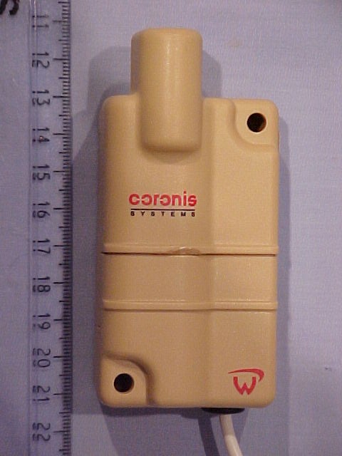
S28WFLTelemetry Modem

Coronis Systems
Telemetry Modem - FCC ID S28WFL - Coronis Systems
Click to zoom

Application Details

Equipment Class
DSS - Part 15 Spread Spectrum Transmitter
Date of Grant
Mar 15, 2005
Application Purpose
Original Equipment
Date of Application
Mar 15, 2005
Equipment Note
Telemetry Modem
Frequency Range
907.02720000 - 921.48480000
Company
Coronis Systems
Country
France

Documents & Files

Select a file to view

Users Manual

↗
↗

Cover Letter(s)

↗

External Photos

↗

ID Label/Location Info

↗

Internal Photos

↗

Test Report

Test Setup Photos

↗

Document Text

Text extracted from the exhibit documents filed with the FCC. Open a document above to read the original.

Users Manual

File : CS-SUP-MUTI-WTHERMAPP-E01.sxw WaveTherm modules – application handbookpage 1 of 65 File : CS-SUP-MUTI-WTHERMAPP-E01.sxw REVISIONS HISTORY Rev. #DescriptionAuthorDateComments 1Original documentRCS02/02/05Version 1 2Addon text FCCRCS17/02/05Version 2 SUPPORTED FIRMWARE VERSION ➢WaveTherm - DALLAS European Version Manual versionFirmware versionDate 1.0V 01.0415/10/04 US Version Manual versionFirmware versionDate 1.0V 81.0515/10/04 ➢WaveTherm - PT100 Manual versionFirmware versionDate 1.0V 01.0215/10/04 ➢WaveTherm - PT1000 Manual versionFirmware versionDate 1.0V 01.0015/10/04 This device complies with part 15 of the FCC rules. Operation is subject to the following two conditions : this device may not cause harmful interference, and this device must accept any interference received, including interference that may cause undesired operation. Caution : any changes or modifications not expressly approved by Coronis- Systems could void the user's authority to operate the equipment. WaveTherm modules – application handbookpage 2 of 65 File : CS-SUP-MUTI-WTHERMAPP-E01.sxw TABLE OF CONTENTS 1 PRESENTATION...........................................................................................................................6 2 REFERENCE DOCUMENTS.........................................................................................................6 3 PRESENTATION OF THE WAVETHERM MODULES FUNCTIONALITIES................................7 3.1 SENSORS INTERFACE.........................................................................................................................7 3.2 READ TEMPERATURES.......................................................................................................................8 3.3 PERIODIC TEMPERATURE READING (DATALOGGING)..................................................................8 3.4 MANAGEMENT OF THRESHOLD ALARMS........................................................................................9 3.4.1 Threshold Alarm Detection.............................................................................................................9 3.4.2 Storage of Threshold Alarm occurences........................................................................................9 3.4.3 Transmission of a Threshold Alarm Frame.....................................................................................9 3.5 STORAGE OF CALIBRATION PARAMETERS..................................................................................10 3.6 WAKE-UP SYSTEM MANAGEMENT..................................................................................................10 3.7 AUTOMATIC TRANSMISSION OF FAULTS......................................................................................10 3.8 SENSOR FAULT DETECTION (IF SUPPORTED BY THE MODULE)...............................................11 3.9 END OF BATTERY LIFE DETECTION................................................................................................11 4 DATA EXCHANGE PRINCIPLE WITH A WAVETHERM MODULE ..........................................12 5 INFORMATION RELATIVE TO THE PROBES ASSOCIATED WITH THE WAVETHERM MODULES ......................................................................................................................................15 5.1 DALLAS PROBES...............................................................................................................................15 5.1.1 Coding of temperatures for the DALLAS probe type DS18B20 ...................................................15 5.1.2 Probe ID........................................................................................................................................15 5.1.3 Setting of the probe coefficient parameters..................................................................................16 5.2 PT100 AND PT1000 PROBES.............................................................................................................17 5.2.1 Representation of temperature values..........................................................................................17 5.2.2 Calibration of radio module...........................................................................................................18 5.2.3 Setting of probe coefficient parameters........................................................................................19 6 MODIFICATION OF THE INTERNAL PARAMETERS................................................................21 6.1 INTERNAL PARAMETERS LIST ACCESSIBLE BY RADIO COMMANDS.......................................21 6.1.1 Parameters common to all WAVETHERM versions.....................................................................21 6.1.2 Parameters specific to the WaveTherm – DALLAS module.........................................................22 6.1.3 Parameters specific to the WaveTherm – PT100 module............................................................22 6.1.4 Parameters specific to theWaveTherm – PT1000 module...........................................................23 6.1.5 Definition of the module control bytes...........................................................................................24 6.2 PRINCIPLE OF READING AND WRITING OF INTERNAL PARAMETERS......................................25 WaveTherm modules – application handbookpage 3 of 65 File : CS-SUP-MUTI-WTHERMAPP-E01.sxw 7 WAVETHERM MODULE FUNCTIONS ......................................................................................27 7.1 PARAMETER SETTING OF THE WAVETHERM MODULE...............................................................27 7.1.1 Reading of the module type..........................................................................................................27 7.1.2 Reading of the firmware version...................................................................................................28 7.1.3 Reading of the date and time of the module.............…

Text truncated - open the document above for the full version.

Users Manual

File : CS-SUP-MUTI-WTHERMSPETEC-E02.sxw WaveTherm module technical specificationspage 1 of 31 File : CS-SUP-MUTI-WTHERMSPETEC-E02.sxw LIST OF UPDATES Update #DescriptionAuthorDateComments 1First editionRCS22/11/04Version 1 2Add-on FCC textRCS17/02/05Version 2 REFERENCE DOCUMENTS Ref.TitleReferenceVersionDate DR[1]WaveCard user handbook This device complies with part 15 of the FCC rules. Operation is subject to the following two conditions : this device may not cause harmful interference, and this device must accept any interference received, including interference that may cause undesired operation. Caution : any changes or modifications not expressly approved by Coronis- Systems could void the user's authority to operate the equipment. WaveTherm module technical specificationspage 2 of 31 File : CS-SUP-MUTI-WTHERMSPETEC-E02.sxw TABLE OF CONTENTS 1 PRESENTATION OF THE WAVETHERM MODULE ....................................................................................4 1.1 CHARACTERISTICS..............................................................................................................................4 1.2 SENSOR INTERFACE...........................................................................................................................6 1.2.1 WaveTherm – DALLAS..................................................................................................................6 1.2.2 WaveTherm – PT1000....................................................................................................................7 1.2.3 WaveTherm – PT100......................................................................................................................8 1.3 WAVETHERM MODULE OPERATING LIFE ........................................................................................9 1.3.1 Parameters with an influence on average power consumption......................................................9 1.3.2 Estimation of operating life............................................................................................................10 1.3.3 Influence of Datalogging mode measurement period...................................................................11 2 INFORMATION RELATIVE TO THE PROBES ASSOCIATED WITH THE WAVETHERM MODULES ....13 2.1 DALLAS PROBES...............................................................................................................................13 2.1.1 Coding of températures for the DALLAS probe type DS18B20 ...................................................13 2.1.2 Probe Id........................................................................................................................................13 2.1.3 setting of the probe coefficient parameters...................................................................................13 2.2 PT100 AND PT1000 PROBES.............................................................................................................14 2.2.1 Representation of temperature values..........................................................................................14 2.2.2 Calibration of radio module ..........................................................................................................15 2.2.3 Setting of probe coefficient parameters........................................................................................15 3 INSTALLATION OF A WAVETHERM MODULE ........................................................................................17 3.1 MODULE FASTENING.........................................................................................................................17 3.2 INSTALLATION PRECAUTIONS........................................................................................................17 3.3 REPLACEMENT OF A MEASUREMENT PROBE..............................................................................18 4 DATA EXCHANGE PRINCIPLE WITH A WAVETHERM MODULE ...........................................................20 5 WAVETHERM MODULE FUNCTIONS .......................................................................................................21 5.1 READ TEMPERATURES.....................................................................................................................21 5.1.1 information concerning precision..................................................................................................21 5.1.2 Read ohmic value of probes immediately.....................................................................................21 5.2 STORAGE OF CALIBRATION PARAMETERS .................................................................................22 5.3 PERIODIC TEMPERATURE READING (DATALOGGING)................................................................23 5.4 AUTOMATIC TRANSMISSION OF FAULTS......................................................................................24 5.4.1 Alarm management parameter setting.........................................................................................24 5.4.2 Triggering an alarm frame............................................................................................................24 5.5 WAKE-UP SYSTEM MANAGEMENT..................................................................................................24 5.5.1 Choice of wake-up mode..............................................................................................................25 5.5.2 Set a new wake-up period............................................................................................................26 5.5.3 Set a fixed wake-up period for certain days of the week..............................................................27 5.5.4 Set day/night system parameter without distinction of days of the week....................................27 5.5.5 Set the day/night system parameters according to day of the week...........................................27 5.6 MANAGE…

Text truncated - open the document above for the full version.

Cover Letter(s)

March 8 th 2005 Telecommunication Certification Body RFI Global Services Ltd. Pavilion A Ashwood Park Basingstoke Hampshire RG23 8BG United Kingdom Subject: Certification Application FCC ID: S28 It is requested that the following information is to be held confidential on behalf of CORONIS- SYSTEMS. FCC Rules Part 0.459 refers. Schematics 16 files of 1 page FileFileFileFile CS-SCH-044-US-Fsp.pdfCS-SCH-051-US-Hsp.pdfCS-SCH-086-US-B2sp.pdfCS-SCH-087-US-Dsp.pdf CS-SCH-044-US-Fsp-DATA PROCESSING.pdf CS-SCH-051-US-Hsp-DATA PROCESSING.pdf CS-SCH-086-US-B2sp-DATA PROCESSING.pdf CS-SCH-087-US-Dsp-DATA PROCESSING.pdf CS-SCH-044-US-Fsp-POWER SUPPLY.pdf CS-SCH-051-US-Hsp-POWER SUPPLY.pdf CS-SCH-086-US-B2sp-POWER SUPPLY.pdf CS-SCH-087-US-Dsp-POWER SUPPLY.pdf CS-SCH-044-US-Fsp-RF.pdfCS-SCH-051-US-Hsp-RF.pdfCS-SCH-086-US-B2sp-RF.pdfCS-SCH-087-US-Dsp-RF.pdf Block diagram 2 files : Filenumber of pages block diagram_Watherm.pdf 1 block diagram_Watport.pd 1 Operational description 2 files : Filenumber of pages Operational description_Wavetherm.pdf 1 Operational description_Waveport.pdf 1 Page 1 / 2 Part list : 4 files Filenumber of pages CS-NOM-091-US-B2sp.pdf 6 CS-NOM-092-US-Dsp.pdf 6 CS-NOM-055-US-Hsp.pdf 4 CS-NOM-046-US-Fsp.pdf 6 This information have to be held confidential to our competitor. They are part of industrial secret. Yours sincerely Page 2 / 2

ID Label/Location Info

Client: Projet: FCC Document: FCC LABEL LAYOUT Date: 03/02/05 Version: Ref: FCC LABEL LAYOUT Wavetherm, Waveflow and Wavesense Label 1 Label 2 Highly ConfidentialThis document is the property of CoronisPage 1 / 2 label 1 label 2 Product name Part number FFC ID Serial number Bar code S28 WFL

Contact Information

Applicant

Fabien F. Bonjour(Mr)
fabien.bonjour@coronis-systems33 (0)4 67 22 66 70Fax: 33 (0)4 67 22 66 71

Test Firm

RFI Global Services Ltd.Allan Hume
[email protected]44-1256-855439Fax: 44-1256-851195

Technical Specifications

#Rule PartsFrequency RangePower Output
115C907.0272 MHz - 921.4848 MHz2.20 mW
Modular Type
Limited Single Modular Approval
Confidentiality
Long Term
Grant Notes
Limited modular approval. The antenna(s) used for this transmitter must be installed to provide a separation distance of at least 20cm from all persons and must not be co-located or operating in conjunction with any other antenna of transmitter. This module is approved for use when installed in the following products Wavetherm, Wavesense, Waveflow and Labguard.

Other Applications from Coronis Systems
Radio Modem - FCC ID S28WPO - Coronis Systems
S28WPO

Radio Modem

Mar 14, 2005

Equipment Class

DSS - Part 15 Spread Spectrum Transmitter