S2OADRFTECH002PCS Repeater
Advanced RF Technologies, Inc.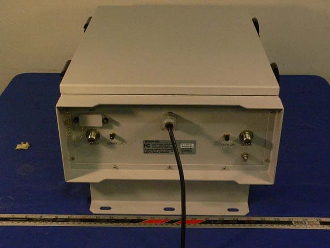
Click to zoom
Application Details
- Equipment Class
- AMP - Amplifier
- Date of Grant
- Nov 07, 2005
- Application Purpose
- Original Equipment
- Date of Application
- Nov 07, 2005
- Equipment Note
- PCS Repeater
- Frequency Range
- 1930.00000000 - 1990.00000000
- Country
- United States
Documents & Files
Document Text
Text extracted from the exhibit documents filed with the FCC. Open a document above to read the original.
Users Manual
EPOCH-S02-19001W U SER MANUAL Version 1.0 Epoch-S02-19001W RF Repeater User Manual V1.0 Advanced RF Technologies, Inc. Proprietary Document Page 2 of 32 Version 1.0 (Modified October 12, 2005) Information in this document is subject to change without notice. Advanced RF Technologies, Inc. 1996-2005. All rights reserved. Please send comments to: E-Mail: [email protected] Phone: (323) 254-8131 Fax: (323) 254-4928 Address: Advanced RF Technologies, Inc. Attention: Technical Publications Department 2607 Colorado Blvd., Suite 100 Los Angeles, CA 90041 USA Epoch-S02-19001W RF Repeater User Manual V1.0 Advanced RF Technologies, Inc. Proprietary Document Page 3 of 32 TABLE OF CONTENTS 1. Installation Guide for Epoch-S02-19001W...........................................................5 1.1 Environmental Requirements..........................................................................5 1.1.1 Antenna Separation/Isolation...........................................................5 1.1.2 Line of Sight.....................................................................................6 1.2 Warnings and Hazards ...................................................................................7 1.3 Tools and Recommendations for Installation..................................................8 1.4 Epoch-S02-19001W Parts List .......................................................................8 1.5 Epoch-S02 1W OMS V1.XX Installation and Requirements ..............................9 1.5.1 Minimum Requirements ..................................................................9 1.5.2 Epoch-S02 1W OMS V1.XX Installation ............................................9 1.5.3 Initial Startup of Epoch-S02 1W OMS V1.XX.....................................9 1.6 Pre-Installation using Epoch-S02 1W OMS V1.XX .........................................10 1.7 Step by Step Instructions for Installation ......................................................10 1.7.1 Repeater Setup...............................................................................10 2 User Manual V1.0 using Epoch-S02 1W OMS V1.XX .......................................15 2.1 Menu Structure.............................................................................................15 2.1.1 Window Overview...........................................................................15 2.1.2 Status Window ...............................................................................16 2.1.3 Control Menu .................................................................................17 2.1.3.1 General Setting Window...................................................17 2.1.3.2 Alarm Setting Window .....................................................19 2.1.4 Install Window ...............................................................................20 2.1.5 System Information........................................................................21 2.2 Using the Epoch-S02 1W OMS V1.XX............................................................22 2.2.1 Changing Parameters.....................................................................22 2.3 Alarms..........................................................................................................23 2.3.1 General (Fixed Parameter) Alarms ..................................................24 2.3.2 Downlink/Uplink Alarms ................................................................24 2.4 Default Control Settings ...............................................................................25 2.4.1 Default General Setting ..................................................................25 2.4.2 Default Alarm Setting.....................................................................25 3 Maintenance Guide for Epoch-S02-19001W ..................................................26 3.1 Periodic Inspection Checklist........................................................................26 3.2 Preventive Measures for Optimal Operation .................................................26 3.2.1 Recommendations .........................................................................26 3.2.2 Precautions ....................................................................................26 4 Troubleshooting.............................................................................................27 4.1 Epoch-S02 1W OMS V1.XX Scenarios............................................................27 4.2 Common Installation Problems.....................................................................27 Epoch-S02-19001W RF Repeater User Manual V1.0 Advanced RF Technologies, Inc. Proprietary Document Page 4 of 32 5 Warranty and Repair Policy .............................................................................29 5.1 General Warranty..........................................................................................29 5.2 Limitations of Warranty ................................................................................29 Appendix A: Specifications ............................................................................................31 A.1 Repeater Specifications ................................................................................31 Epoch-S02-19001W RF Repeater User Manual V1.0 Advanced RF Technologies, Inc. Proprietary Document Page 5 of 32 1. Installation Guide for Epoch-S02-19001W 1.1 Environmental Requirements 1.1.1 Antenna Separation/Isolation Separation between antennas is necessary to prevent oscillation. Oscillation occurs when the signal entering the system continually reenters, due to the lack of separation between the donor and server antennas. In other words, the signal is being fed back into the system. This creates a constant amplification of the same signal. As a result, the noise level rises above the signal level. To prevent feedback, the donor and server antennas must be separated by an appropriate distance to provide sufficient isolation. Isolati…
Text truncated - open the document above for the full version.
External Photos
EXHIBIT C - EUT EXTERNAL PHOTOGRAPHS EUT – Front View EUT – Rear View EUT – Side View Power Supply (MPSA300-270605-F) View 1
ID Label/Location Info
EXHIBIT A - FCC PRODUCT LABELING AND WARNING STATEMENT FCC ID Label Specifications : Text is black or white in color and is left justified. Labels are silk-screened and shall be “permanently affixed” at a conspicuous location on the EUT. Proposed Label Location on EUT EUT Front View / Label Location FCC Warning Statement A FCC Warning Statement is provided in the product manual.
Internal Photos
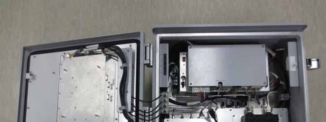
EXHIBIT C – EUT INTERNAL PHOTOGRAPHS EUT – Open Chassis View1 EUT - Open Chassis View2 EUT - Open Chassis View3 Control Board (EMU04-001 & 002) - Control board Ass'y Control Board EMU-04-001 – Top View Control Board EMU-04-001 – Bottom View Control Board EMU-04-002 – Top View Control Board EMU-04-002 – Bottom View Isolation Module (EMM-04-040) – Board1 Top View Isolation Module (EMM-04-040) – Board1 Bottom View Isolation Module (EMM-04-040) – Board2 Top View Isolation Module (EMM-04-040) – Board2 Bottom View Isolation Module (EMM-04-040) – Unit External_Front Isolation Module (EMM-04-040) – Unit External Rear Isolation Module (EMM-04-040) – Unit internal Sub Board (EMU-04-004) – Top View Sub Board (EMU-04-004) – Bottom View UDC Module (EMM-04-038) - Circuit Board Front Top UDC Module (EMM-04-038) - Circuit Board Front Bottom UDC Module (EMM-04-038) - Unit external front UDC Module (EMM-04-038) - Unit external Rear UDC Module (EMM-04-038) - Unit Internal Front UDC Module (EMM-04-038) - Unit Internal Rear UDC Module (EMM-04-039) - Circuit board Front Top UDC Module (EMM-04-039) - Circuit board Rear Top UDC Module (EMM-04-039) - Unit external front UDC Module (EMM-04-039) - Unit external Rear UDC Module (EMM-04-039) - Unit Internal front UDC Module (EMM-04-039) - Unit Internal Rear Power Supply (MPSA300-270605-F) View 2 Power Supply (MPSA300-270605-F) View 3
Operational Description
EPOCH-S02-19001W OPERATIONAL DESCRIPTION ~ 1 W Composite Output Power ~ Advanced RF Technologies, Inc. 2607 Colorado Blvd., Los Angeles, CA 90041 Tel: (323) 254-8131 Fax: (323) 254-4928 www.adrftech.com Advanced RF Technologies, Inc. Proprietary Document 2 Block Diagram Figure 1: Epoch-S02-19001W Block Diagram Figure 1 describes the operation of the Epoch-S02-19001W repeater. The donor antenna points to and receives the signal from the BTS and feeds it to the downlink (DL) path of the repeater. The DL signal is amplified and radiated by the server antenna. On the other side, the uplink (UL) signal from the mobile station (MS) is received by the server antenna, amplified by the repeater and reradiated by the donor antenna to the BTS. Control Board CDMA MODEM MODULE ANT FL_AGC ATT #1~4 FL_5MHz Synthesizer RL_15MHz Synthesizer PLL DATA AC/DC Power Supply +12V +6V Alarm (VSWR, DOOR OPEN, PLL LOCK etc ) FL_Gain ADJ ATT FL_15MHz Synthesizer RL_5MHz Synthesizer FL _15M LOCAL #1 FL _15M LOCAL #2 FL _5M LOCAL #1 FL _5M LOCAL #2 FL_IN DET #1 FL_IN DET #2 15MHz SAW FL_AGC ATT #1 V_ATT LNA Mixer Isolator Filter Filter AMP 2W S/P AMP FL_AGC ATT #2 Mixer AMP Filter FL_15M LOCAL #2 FL_15M LOCAL #1 5MHz SAW FL_AGC ATT #3 Mixer Filter AMP AMP FL_AGC ATT #4 Mixer AMP Filter FL_5M LOCAL #2 FL_5M LOCAL #1 ISO_DET MODULE Coupler Input Detector FL_IN DET #1 V_ATT V_ATT V_ATT AMP Thermal PAD AMP AMP FilterCoupler Output Detector FL_IN DET #2 V_ATT FL_Gain ADJ ATT AMP Filter HPA FL_OUT DET #2 FL_OUT DET #2 RL _15M LOCAL #1 RL _15M LOCAL #2 RL _5M LOCAL #1 RL _5M LOCAL #2 +5V Battery +12V OUTPUT ON/OFF Status Isolation Detection Module FL_Signal RL_Signal Check LOW ISO /OSC 15MHz SAW RL_AGC ATT #1 LNA Mixer Isolator V_ATT Filter FilterAMP 2W S/P AMP RL_AGC ATT #2 Mixer AMP Filter RL_15M LOCAL #2 RL_15M LOCAL #1 5MHz SAW RL_AGC ATT #3 Mixer FilterAMPAMP RL_AGC ATT #4 Mixer AMP Filter RL_5M LOCAL #2 RL_5M LOCAL #1 ISO_DET MODUL E Coupler Input Detector RL_IN DET #1 V_ATTV_ATT V_ATT AMP Thermal PAD AMP AMP Filter Coupler Output Detector RL_IN DET #2 V_ATT RL_Gain ADJ ATT AMP Filter HPA RL_OUT DET #2 Forward Link Reverse Link RL_AGC ATT #1~4 RL_Gain ADJ ATT RL_IN DET #1 RL_IN DET #2 RL_OUT DET #2 Donor Antenna Server Antenna Advanced RF Technologies, Inc. Proprietary Document 3 Downlink Signal Flow When the RF signal from the BTS (base station) comes through the donor antenna and into our repeater, it goes to the donor duplexer which separates the UL and DL frequencies. The RF signal then goes to the LNA (Low Noise Amplifier) and its main purpose is to reduce the total noise figure of the DL RF signal which will be later amplified. After the LNA, the DL RF signal goes through the Coupler so that the input signal level can be monitored. This RF signal then goes through a splitter and a switch, which will allow the RF signal to go through either one of the paths (5 MHz or 15 MHz) or both (5 MHz & 15 MHz). The RF signal(s) goes to a Mixer which down-converts the RF signal (PCS Bands) into IF frequencies, which then goes through the first stage of AGC (Automatic Gain Control) circuitry in order to set the correct gain on the repeater. The IF signal will then go through either one or both SAW filters (5 MHz & 15 MHz) to properly select the desired operating PCS band or bands. The IF signal(s) then goes through the second stage of AGC (Automatic Gain Control) circuitry in order to set the correct gain on the repeater. The IF signal is then up converted back to RF again and goes through Ceramic filter(s) to reject unwanted spurious and harmonic signals. The RF signal(s) are then combined and goes through a Thermal PAD, so that the combined system gain is compensated according to the system temperature. The RF signal goes through the Coupler through which the output signal level can be monitored. The RF signal then goes through a Variable Attenuator which will adjust the total system gain and then goes to the Isolator, which prevents feedback from the HPA (High Power Advanced RF Technologies, Inc. Proprietary Document 4 Amplifier). Finally, the RF signal goes through the Power Amplifier or PA which basically amplifies the RF signal. The amplified RF signal then goes through the server duplexer and the DL RF signal is finally radiated from the server antenna. Uplink Signal Flow When the RF signal from the MS (Mobile Station) comes through the server antenna and into our repeater, it goes to the server duplexer which separates the UL and DL frequencies. The RF signal then goes to the LNA (Low Noise Amplifier) and its main purpose is to reduce the total noise figure of the UL RF signal which will be later amplified. After the LNA, the UL RF signal goes through the Coupler so that the input signal level can be monitored. This RF signal then goes through a splitter and a switch, which will allow the RF signal to go through either one of the paths (5 MHz or 15 MHz) or both (5 MHz & 15 MHz). The RF signal(s) goes to a Mixer which down-converts the RF signal (PCS Bands) into IF frequencies, which then goes through the first stage of AGC (Automatic Gain Control) circuitry in order to set the correct gain on the repeater. The IF signal will then go through either one or both SAW filters (5 MHz & 15 MHz) to properly select the desired operating PCS band or bands. The IF signal(s) then goes through the second stage of AGC (Automatic Gain Control) circuitry in order to set the correct gain on the repeater. The IF signal is then up converted back to RF again and goes through Ceramic filter(s) to reject unwanted spurious and harmonic signals. The RF signal(s) are then combined and goes through a Thermal PAD, so that the combined system gain is compensated according to the system temperature. The RF Advanced RF Technologies, Inc. Proprietary Document 5 signal goes through the Coupler through which the output signal level can be monitored. The RF signal then goes through a Variable Attenuator which will adjust the total system gain and then…
Text truncated - open the document above for the full version.
Parts List/Tune Up Info
2607 Colorado Blvd. Los Angeles, CA 90041 TEL: (323) 254-8131 FAX: (323) 254-4928 www.adrftech.com ________________________________________________________________________ Tune-Up Procedure (Epoch-S02-19001W) I. Connecting the Laptop to the Repeater 1. Connect the RS-232 straight-through serial cable (included in the box) to the NMS port (labeled as # 1) on the bottom of the Epoch-S02-19001W as shown below. Connect the other end of the RS-232 straight-through serial cable to the serial port on the PC. # 1 - NMS Port 2. Open the OMS software by double clicking the software icon. The following window will be displayed: Advanced RF Technologies, Inc. Proprietary Document 1 3. Check the communication port on the bottom of the GUI (Graphical User Interface) window. If you see the following prompt “COM Port 1 Successfully Opened” on the lower left portion of the window, the OMS software and the laptop can communicate with each other properly. For example, if “COM Port 1 Failed To Open” appears, choose a different Com Port as shown below until proper communication is established. II. Turn the Epoch-S02-19001W Power On 1. Turn on the repeater’s main power located inside the repeater. 2. On the lower right corner of the GUI window, you can see both the TX and the RX green lights are blinking periodically. This implies that the Epoch-S02-19001W and the PC are communicating properly. 3. Verify on the Status Window that the modem box is highlighted and is showing as connected. This may take a few minutes once the repeater is powered on. Note: The above step only applies if a wireless modem is connected to the repeater. III. Go to Install Menu 1. Go to the “Install” Menu, you will see the following screen. 2 3 4 5 Advanced RF Technologies, Inc. Proprietary Document 2 2. On the Installation screen, select the desired operating “Band.” By default, the A band is selected. Note: Steps 3 & 4 should be followed only if a wireless modem is connected to the repeater. 3. Verify that the “Auto Connection” button is checked (default setting). 4. Enter the Site ID and the Manager IP as provided by the wireless provider. Click the “Set” button once the parameters are typed in. 5. Hit the “Install” button. Once the button is hit, the Epoch-S02-19001W will be checking various parameters automatically (e.g. Band Selection, RSSI, Isolation, Alarm, Heartbeat, etc) and set the different parameters for the repeater accordingly (e.g. Gain, Output Power, etc.). If “Installation Successfully Completed” dialog box appears, the Epoch-S02-19001W repeater has been successfully installed. This installation process typically takes less than 5 minutes if all the above steps are followed and the conditions are met. IV. Trouble Shooting It would be very rare, but if you unfortunately have an “Installation Incomplete” message, please contact the Technical Support Department at: E-Mail: [email protected] Phone: 323-254-8131 Advanced RF Technologies, Inc. Proprietary Document 3
Test Report
Note: This test report is specially limited to the above client company and this particular sample only. It may not be duplicated without prior written consent of Bay Area Compliance Laboratory Corporation. This report must not be used by the client to claim product certification, approval, or endorsement by NVLAP, NIST or any agency of the U.S. Government. FCC PART 24 TYPE APPROVAL EMI MEASUREMENT AND TEST REPORT For Advanced RF Technologies, Inc. 5440 Trabuco Road Irvine, CA 92620 FCC ID: S2OADRFTECH002 This Report Concerns: Original Report Equipment Type: PCS Repeater Test Engineer: James Ma/ Report No.: R0509152 Report Date: 2005-10-14 Reviewed By: Daniel Deng / Prepared By: Bay Area Compliance Laboratory Corporation 230 Commercial Street Sunnyvale, CA 94085 Tel: (408) 732-9162 Fax: (408) 732 9164 Advanced RF Technologies, Inc. FCC ID: S2OADRFTECH002 Report # R0509152Rpt Page 2 of 48 FCC Part 24 Type Approval report TABLE OF CONTENTS GENERAL INFORMATION.......................................................................................................................................4 PRODUCT DESCRIPTION FOR EQUIPMENT UNDER TEST (EUT) ....................................................................................4 OBJECTIVE...................................................................................................................................................................4 RELATED SUBMITTAL(S)/GRANT(S).............................................................................................................................4 TEST METHODOLOGY..................................................................................................................................................4 TEST FACILITY.............................................................................................................................................................4 SYSTEM TEST CONFIGURATION ..........................................................................................................................6 JUSTIFICATION.............................................................................................................................................................6 BLOCK DIAGRAM.........................................................................................................................................................6 EQUIPMENT MODIFICATIONS.......................................................................................................................................6 LOCAL SUPPORT EQUIPMENT LIST AND DETAILS........................................................................................................6 EXTERNAL I/O CABLING LIST AND DETAILS...............................................................................................................6 TEST SETUP BLOCK DIAGRAM.....................................................................................................................................6 SUMMARY OF TEST RESULTS ...............................................................................................................................7 §2.1046 & §24.232 - RF POWER OUTPUT................................................................................................................8 APPLICABLE STANDARD..............................................................................................................................................8 TEST PROCEDURE........................................................................................................................................................8 TEST EQUIPMENT LIST AND DETAILS...........................................................................................................................8 ENVIRONMENTAL CONDITIONS....................................................................................................................................8 TEST RESULTS.............................................................................................................................................................9 §2.1049 & §24.238 - EMISSION BANDWIDTH ......................................................................................................11 APPLICABLE STANDARDS..........................................................................................................................................11 TEST PROCEDURE......................................................................................................................................................11 TEST EQUIPMENT LIST AND DETAILS.........................................................................................................................11 ENVIRONMENTAL CONDITIONS..................................................................................................................................11 TEST RESULTS...........................................................................................................................................................12 §2.1051 & §24.238(A) - SPURIOUS EMISSIONS AT ANTENNA TERMINALS................................................22 APPLICABLE STANDARDS..........................................................................................................................................22 TEST PROCEDURE......................................................................................................................................................22 TEST EQUIPMENT LIST AND DETAILS.........................................................................................................................22 ENVIRONMENTAL CONDITIONS..................................................................................................................................22 TEST RESULTS...................................................................................................................................................…
Text truncated - open the document above for the full version.
Contact Information
Applicant
Julie Song(C.E.O)
Test Firm
Bay Area Compliance LaboratoryJohn Chan
Technical Specifications
| # | Rule Parts | Frequency Range | Power Output | Emission |
|---|---|---|---|---|
| 6 | 24E | 1.93 GHz - 1.99 GHz | 977.00 mW | 97K5DXW |
Other Applications from Advanced RF Technologies, Inc.
S2O-AXM2100-9543I
Jun 08, 2014REPEATER
Equipment Class
B2I - Part 20 Industrial Booster (CMRS)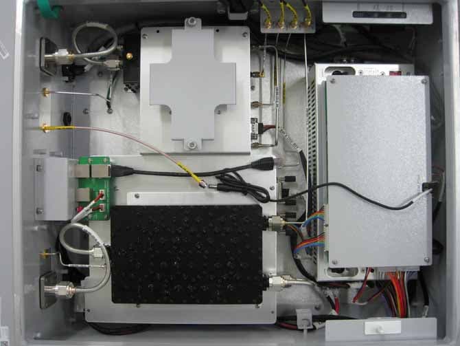
S2O-AXM1900-9543I
May 07, 2014Repeater
Equipment Class
B2I - Part 20 Industrial Booster (CMRS)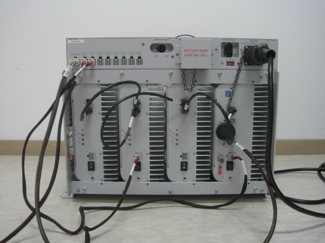
S2O-ADX-R-C30S
May 21, 2012DAS(Distributed Antenna System)
Equipment Class
AMP - Amplifier
S2O-ADX-R-P30M
May 21, 2012DAS(Distributed Antenna System)
Equipment Class
AMP - Amplifier
S2O-ADX-R-A30S
May 21, 2012DAS(Distributed Antenna System)
Equipment Class
AMP - Amplifier