S2OADRFTECH003Epoch- M1P Repeater
Advanced RF Technologies, Inc.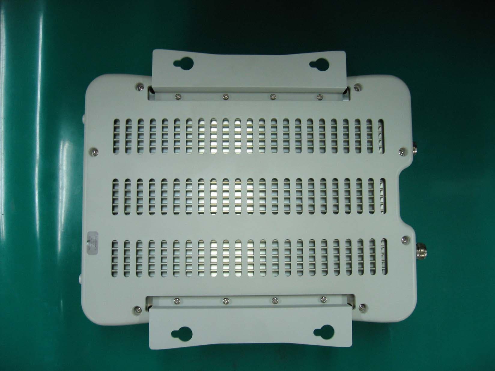
Click to zoom
Application Details
- Equipment Class
- PCB - PCS Licensed Transmitter
- Date of Grant
- May 10, 2006
- Application Purpose
- Original Equipment
- Date of Application
- May 10, 2006
- Equipment Note
- Epoch- M1P Repeater
- Frequency Range
- 1930.00000000 - 1990.00000000
- Country
- United States
Documents & Files
Document Text
Text extracted from the exhibit documents filed with the FCC. Open a document above to read the original.
Users Manual
EPOCH-M1P U SER MANUAL Version 1.0 2607 Colorado Blvd. Los Angeles, CA 90041 USA Tel: 323-254-8131 Fax: 323-254-4928 www.adrftech.com Epoch-M1P RF Repeater User Manual V1.0 Version 1.0 (Released May 4, 2006) Information in this document is subject to change without notice. Advanced RF Technologies, Inc. 1996-2006. All rights reserved. Please send comments to: E-Mail: [email protected] Phone: (323) 254-8131 Fax: (323) 254-4928 Address: Advanced RF Technologies, Inc. Attention: Technical Publications Department 2607 Colorado Blvd., Suite 100 Los Angeles, CA 90041 USA www.adrftech.com Advanced RF Technologies, Inc. Proprietary Document Page 2 of 38 Epoch-M1P RF Repeater User Manual V1.0 TABLE OF CONTENTS 1. Introduction of Epoch-M1P.................................................................................5 1.1 Overview......................................................................................................5 1.1.1 Highlights......................................................................................5 1.1.2 Special Features..............................................................................5 1.1.3 Available Models............................................................................7 1.2 Warnings and Hazards..................................................................................8 1.3 Epoch-M1P Parts List....................................................................................9 1.4 Software Installation and Requirements .....................................9 Epoch-M1P 1.4.1 Minimum Requirements....................................................................9 1.4.2 Software Installation....................................................10Epoch-M1P 1.4.3 Initial Startup of Software ............................................10 Epoch-M1P 1.5 Pre-Installation using Epoch-M1P Software ................................................10 1.6 Step by Step Instructions for Installation.....................................................11 1.6.1 Repeater Setup .............................................................................11 2 User Manual V1.0 using Epoch-M1P Software ....................................................15 2.1 Menu Structure...........................................................................................15 2.1.1 Window Menu...............................................................................15 2.1.2 Status Menu.................................................................................16 2.1.3 Control Menu...............................................................................17 2.1.3.1 General Setting Window..................................................17 2.1.3.2 Alarm Setting Window....................................................19 2.1.4 Install Menu..................................................................................20 2.1.5 System Menu................................................................................23 2.1.5.1 Info. Window..................................................................23 2.1.5.2 Upgrade Window............................................................24 2.2 Using the Epoch-M1P Software ..................................................................25 2.2.1 Changing Parameters...................................................................25 2.3 Alarms........................................................................................................25 2.3.1 General (Fixed Parameter) Alarms.................................................26 2.3.2 Downlink/Uplink Alarms...............................................................27 2.4 Default Control Settings..............................................................................27 2.4.1 Default General Setting.................................................................27 2.4.2 Default Alarm Setting...................................................................28 3 Maintenance Guide for Epoch-M1P....................................................................28 3.1 Periodic Inspection Checklist......................................................................28 3.2 Preventive Measures for Optimal Operation.................................................28 3.2.1 Recommendations........................................................................28 3.2.2 Precautions..................................................................................28 4 Troubleshooting................................................................................................29 4.1 Tx & Rx LEDs ..............................................................................................29 Advanced RF Technologies, Inc. Proprietary Document Page 3 of 38 Epoch-M1P RF Repeater User Manual V1.0 4.2 Common Installation Problems...................................................................30 5 Warranty and Repair Policy.................................................................................31 5.1 General Warranty........................................................................................31 5.2 Limitations of Warranty...............................................................................31 5.3 Limitation of Damages...............................................................................31 5.4 No Consequential Damages........................................................................31 5.5 Additional Limitation on Warranty...............................................................31 5.6 Return Material Authorization (RMA)...........................................................32 Appendix A: Specifications..........................................................................................33 Appendix B: Button Operation......................................................................................35 Advanced RF Technologies, Inc. Proprietary Document Page 4 of 38 Epoch-M1P RF Repeater Use…
Text truncated - open the document above for the full version.
Users Manual
CHECK SIGNAL LEVELS 8 5 INSTALL AND RUN SOFTWARE 4 CONNECT USB, POWER CABLES, AND POWER ON 6 SELECT OPERATING BAND(S) 7 MODEM SETUP Documentation and Software can be found on the CD-ROMincluded in the M1P box. Technical SupportContact ADRF’s Technical Support Team for assistance with:-Software Questions-Setting up the M1P-M1P Operation-Troubleshooting Questions 1 3 CONNECT ANTENNAS/CABLES DONOR SERVER 2 REPEATER PLACEMENT SERVER DONOR Advanced RF Technologies M1P Quick Start Guide USA: 1-323-254-8131www.adrftech.com Quick Install Guide FRONT VIEW TOP VIEW 7 8 *If the M1P does not have a modem inside, proceed to step 8.Make sure the AUTO CONNECTION box is checked.Enter the Site ID and Manager IP information provided by thecarrier.Click SET button and, finally, click “INSTALL” button.When installation is complete, you will get a confirmationmessage.Go to STATUS menu and verify input/output power, gains, etc.Please make sure that there are no ALARMS generated. 5 4 6 Connect the USB cable to your computer andthe M1P.Plug in the power converter. (110VAC)Turn on the M1P. Use the CD-ROM (included in the M1P box)to install the drivers when the NewHardware Wizard comes up. This willensure that the M1P communicatesproperly with the software.Next, install the software from the CD.After installation, launch the software. Go to INSTALL menu on the top of theGUI. On the top of the window, click the5/10/15MHz BAND SELECTION button.Click the center frequency on the pop-upwindow and click OKAY. Double check theSELECTED BAND information. USB/POWER DRIVER/SOFTWARE BAND SELECTION MODEM Set-up POST SURVEY Congratulations! The M1P has beensuccessfully installed and is ready for use.It is recommended to do a walk-throughinside of the building and make live phonecalls to verify RF coverage. 13 2 The box should contain:1 - Epoch-M1P Repeater1 - CD (Software and User Guide)1 - USB Cable1 - AC/DC Power Adapter1 - Quick Install Guide Sheet Locate the place where you will put theM1P. You can hang the M1P or put it onanything. In any case, make sure the M1Pis securely fastened to a wall or anystructure so that it won’t move. Connect the donor/server antenna cables tothe M1P’s antenna ports on top as shown infigure 3.Adjust antenna positioning to assuremaximum coverage. REPEATER PLACEMENT ANTENNA CONNECTION OPEN THE BOX Documentation and Software can be found on the CD-ROMincluded in the M1P box. Technical SupportContact ADRF’s Technical Support Team for assistance with:-Software Questions-Setting up the M1P-M1P Operation-Troubleshooting Questions Advanced RF Technologies M1P Quick Start Guide USA: 1-323-254-8131www.adrftech.com
Users Manual
2607 Colorado Blvd. Los Angeles, CA 90041 TEL: (323) 254-8131 FAX: (323) 254-4928 www.adrftech.com ________________________________________________________________________ Software Setup Guide 1. Insert the installation OMS CD (included in the box) into your PC. 2: When the installation wizard window comes up as shown below, click on NEXT. Advanced RF Technologies, Inc. Proprietary Document 1 2607 Colorado Blvd. Los Angeles, CA 90041 TEL: (323) 254-8131 FAX: (323) 254-4928 www.adrftech.com ________________________________________________________________________ 3. When the following window appears, click on YES. Advanced RF Technologies, Inc. Proprietary Document 2 2607 Colorado Blvd. Los Angeles, CA 90041 TEL: (323) 254-8131 FAX: (323) 254-4928 www.adrftech.com ________________________________________________________________________ 4. Choose the location where you want the software to be installed and click on NEXT. Advanced RF Technologies, Inc. Proprietary Document 3 2607 Colorado Blvd. Los Angeles, CA 90041 TEL: (323) 254-8131 FAX: (323) 254-4928 www.adrftech.com ________________________________________________________________________ 5. Once the following window appears, click NEXT. Advanced RF Technologies, Inc. Proprietary Document 4 2607 Colorado Blvd. Los Angeles, CA 90041 TEL: (323) 254-8131 FAX: (323) 254-4928 www.adrftech.com ________________________________________________________________________ 6. The software should automatically begin to install as shown below: Advanced RF Technologies, Inc. Proprietary Document 5 2607 Colorado Blvd. Los Angeles, CA 90041 TEL: (323) 254-8131 FAX: (323) 254-4928 www.adrftech.com ________________________________________________________________________ 7. After installation has been completed, click on Finish. Note: You will need to remove the older version of the software before installing the newer version. Advanced RF Technologies, Inc. Proprietary Document 6
Users Manual
2607 Colorado Blvd. Los Angeles, CA 90041 TEL: (323) 254-8131 FAX: (323) 254-4928 www.adrftech.com ________________________________________________________________________ USB Driver Setup Guide Note: Make sure you are not connected to the internet during the driver installation. 1. Connect one end of the USB cable to the M1P USB port and the other end to the PC USB port. 2. Once both ends of the USB cable are connected, the following window will appear. Choose Install the software automatically (Recommended) as shown below: Next, place the installation CD-ROM (included in the box) into your CD drive and click Next on the hardware wizard. Advanced RF Technologies, Inc. Proprietary Document 1 2607 Colorado Blvd. Los Angeles, CA 90041 TEL: (323) 254-8131 FAX: (323) 254-4928 www.adrftech.com ________________________________________________________________________ 3. The hardware wizard will search automatically and find the correct drivers from the CD-ROM. 4. When the following window appears: Click on Continue Anyway. Advanced RF Technologies, Inc. Proprietary Document 2 2607 Colorado Blvd. Los Angeles, CA 90041 TEL: (323) 254-8131 FAX: (323) 254-4928 www.adrftech.com ________________________________________________________________________ 5. After installation has been completed, the following window will appear: Click FINISH Advanced RF Technologies, Inc. Proprietary Document 3
ID Label/Location Info
FCC ID : S2OADRFTECH003 S/N: M1P15060001 For In-Building Application Tested To Comply with FCC Standards MODEL NO: EPOCH-M1P-15 Advanced RF Technologies 2607 Colorado Blvd. This device complies with part 15 of the FCC Rules. Operation is subject Los Angeles, CA 90041 to the following two conditions: (1) This device may not cause harmful interference, and (2) this device must accept any interference received, including interference that may cause undesired operation.
ID Label/Location Info
For In-Building & Outdoor Application ATTENTION! Restricted to occupational use Tested To Comply with FCC Standards to satisfy FCC RF exposure limits. See User Manual for operating requirements. Los Angeles, CA 90041 Advanced RF Technologies 2607 Colorado Blvd. FCC ID : S2OADRFTECH003 S/N: M1P15060001 MODEL NO: EPOCH-M1P-05
ID Label/Location Info
For In-Building & Outdoor Application ATTENTION! Restricted to occupational use Tested To Comply with FCC Standards to satisfy FCC RF exposure limits. See User Manual for operating requirements. Los Angeles, CA 90041 Advanced RF Technologies 2607 Colorado Blvd. FCC ID : S2OADRFTECH003 S/N: M1P15060001 MODEL NO: EPOCH-M1P-10
ID Label/Location Info
For In-Building & Outdoor Application ATTENTION! Restricted to occupational use Tested To Comply with FCC Standards to satisfy FCC RF exposure limits. See User Manual for operating requirements. Los Angeles, CA 90041 Advanced RF Technologies 2607 Colorado Blvd. FCC ID : S2OADRFTECH003 MODEL NO: EPOCH-M1P-15 S/N: M1P15060001
ID Label/Location Info
Example Label sticker will be here Front Rear Bottom
Operational Description
2607 Colorado Blvd. Los Angeles, CA 90041 TEL: (323) 254-8131 FAX: (323) 254-4928 www.adrftech.com ______________________________________________________________________________________ Operational Description Figure 1 Figure 1 describes the operation of the Epoch-M1P repeater. The donor antenna points to and receives the signal from the BTS (base station) and feeds it to the downlink (DL) path of the repeater. The DL signal is amplified and radiated by the server antenna. On the other side, the uplink (UL) signal from the MS (mobile station) is received by the server antenna, amplified by the repeater and reradiated by the donor antenna to the BTS. Downlink Signal Flow When the RF signal from the BTS (base station) comes through the donor antenna and into the Epoch-M1P repeater, it goes to the donor duplexer which separates the UL and DL frequencies. The RF signal then goes to the LNA (Low Noise Amplifier) and its main purpose is to reduce the total noise figure of the DL RF signal which will be later amplified. After the LNA, the DL RF signal goes through the Mixer which down-converts the RF signal into IF frequencies. The IF signal(s) will then go through a SAW filter (5, 10 or 15 MHz) to properly select Advanced RF Technologies, Inc. Proprietary Document 1 the desired operating 1900 MHz PCS band or bands. The IF signal then goes through the Coupler so that the input signal level can be monitored. The IF signal then goes through AGC (Automatic Gain Control) circuitry in order to set the correct gain on the repeater. The IF signal(s) are then up-converted (through UDC) back to RF again and goes through Ceramic filter(s) to reject unwanted spurious and harmonic signals. After the Band Pass Filter, the RF signal then goes through a Variable Attenuator which will adjust the total system gain and then goes through the Isolator, which prevents feedback from the HPA (High Power Amplifier). The RF signal goes through the Power Amplifier or PA which basically amplifies the RF signal. The RF signal then goes through the Coupler so that the output signal level can be monitored. The signal then goes through an Isolator and then a Coupler and then through a VSWR detector to check the final connectivity. The amplified RF signal then goes through the server duplexer and the DL RF signal is finally radiated from the server antenna. Uplink Signal Flow When the RF signal from the MS (mobile station) comes through the server antenna and into our repeater, it goes to the server duplexer which separates the UL and DL frequencies. The RF signal then goes to the LNA (Low Noise Amplifier) and its main purpose is to reduce the total noise figure of the UL RF signal which will be later amplified. After the LNA, the UL RF signal goes through the Mixer which down-converts the RF signal into IF frequencies. The IF signal(s) will then go through a SAW filter (5, 10 or 15 MHz) to properly select the desired operating 1900 MHz PCS band or bands. The IF signal then goes through the Coupler so that the input signal level can be monitored. The IF signal then goes through AGC (Automatic Gain Control) circuitry in order to set the correct gain on the repeater. The IF signal(s) are then up-converted (through UDC) back to RF again and goes through Ceramic filter(s) to reject unwanted spurious and harmonic signals. After the Band Pass Filter, the RF signal then goes through a Variable Attenuator which will adjust the total system gain and then goes through the Isolator, which prevents feedback from the HPA (High Power Amplifier). The RF signal goes through the Power Amplifier or PA which basically amplifies the RF signal. The RF signal then goes through the Coupler so that the output signal level can be monitored. The Advanced RF Technologies, Inc. Proprietary Document 2 signal then goes through an Isolator and then a Coupler and then through a VSWR detector to check the final connectivity. The amplified RF signal then goes through the server duplexer and the UL RF signal is finally radiated from the donor antenna. Advanced RF Technologies, Inc. Proprietary Document 3
Parts List/Tune Up Info
110113-0001CHIP BEADCIM31P121NC/3216 4 210113-0104CHIP CAPACITORB104J/0603/25V 39 310113-0150CHIP CAPACITOR150J/0603/50V 2 410113-0331CHIP CAPACITOR331J/0603/50V 5 510113-0680CHIP CAPACITOR680J/0603/50V 1 610113-H132CHIP BEADHH-132JT/1M4532 6 710123-0010CHIP CAPACITOR010C/0805/50V 2 810123-0050CHIP CAPACITOR050J/0805/50V 6 910123-00R5CHIP CAPACITOR0R5J/0805/50V 20 1010123-0100CHIP CAPACITOR100J/0805/50V 4 1110123-0101CHIP CAPACITOR101J/0805/50V 114 1210123-0102CHIP CAPACITOR102J/0805/50V 108 1310123-0103CHIP CAPACITOR103J/0805/50V 39 1410123-0104CHIP CAPACITOR104K/0805/50V 95 1510123-0106CHIP CAPACITOR106K/0805/50V JMK316 BJ106KL-T 42 1610123-0200CHIP CAPACITOR200J/0805/50V 14 1710123-0223CHIP CAPACITOR223J/0805/50V 6 1810123-0270CHIP CAPACITOR270J/0805/50V 2 1910123-0300CHIP CAPACITOR300J/0805/50V 20 2010123-0330CHIP CAPACITOR330J/0805/50V 43 2110123-0430CHIP CAPACITOR430J/0805/50V 6 2210123-0681CHIP CAPACITOR681J/0805/50V 8 2310123-0750CHIP CAPACITOR750J/0805/50V 2 2410123-07R5CHIP CAPACITOR7R5C/0805/50V 8 2510123-0R68CHIP CAPACITOR0R68/0805/50V 2 2610123-2R2CCHIP CAPACITOR2R2C/0805/50V 4 2710213-0106TANTAL CAP10uF/16V/A 10 2810214-0475TANTAL CAP4.7uF/16V/A 1 2910221-0106TANTAL CAP10uF/16V/B 10 3010223-0106TANTAL CAP22uF/16V/B 1 3110242-0107TANTAL CAP100uF/10V/C 10 3210243-0107TANTAL CAP100uF/16V/C 3 3310244-0107TANTAL CAP100uF/16V/D 26 3410244-0476TANTAL CAP47uF/16V/D 2 3510250-0106CAPACITOR DIP16V/10UF/DIP TYPE/6.42¢/85°C 2 3610250-0309CAPACITOR DIP16V/470uf/DIP TYPE/8mm ¢/105°C 2 3710250-0310CAPACITOR DIP35V/470uf/DIP TYPE/8mm ¢/105°C 2 3820112-0000CHIP RESISTOR000C/0603/0.1W 17 3920112-0100CHIP RESISTOR100J/0603/0.1W 2 4020112-0101CHIP RESISTOR101J/0603/0.1W 1 Q'ty Epoch-M1P Parts List CODE-NOTypeDescriptionNO 4120112-0102CHIP RESISTOR102J/0603/0.1W 6 4220112-0103CHIP RESISTOR103J/0603/0.1W 16 4320112-0104CHIP RESISTOR104J/0603/0.1W 1 4420112-0152CHIP RESISTOR152J/0603/0.1W 1 4520112-0154CHIP RESISTOR154J/0603/0.1W 1 4620112-0470CHIP RESISTOR470J/0603/0.1W 1 4720112-0472CHIP RESISTOR472J/0603/0.1W 4 4820112-0510CHIP RESISTOR510J/0603/0.1W 1 4920112-0681CHIP RESISTOR681J/0603/0.1W 2 5020122-0000CHIP RESISTOR000C/0805/0.1W 20 5120122-0100CHIP RESISTOR100J/0805/0.1W 2 5220122-0101CHIP RESISTOR101J/0805/0.1W 44 5320122-0102CHIP RESISTOR102J/0805/0.1W 15 5420122-0103CHIP RESISTOR103J/0805/0.1W 18 5520122-0104CHIP RESISTOR104J/0805/0.1W 2 5620122-0105CHIP RESISTOR105J/0805/0.1W 2 5720122-0132CHIP RESISTOR132J/0805/0.1W 4 5820122-0151CHIP RESISTOR151J/0805/0.1W 6 5920122-0152CHIP RESISTOR152J/0805/0.1W 1 6020122-0153CHIP RESISTOR153J/0805/0.1W 1 6120122-0155CHIP RESISTOR155J/0805/0.1W 1 6220122-0160CHIP RESISTOR160J/0805/0.1W 16 6320122-0180CHIP RESISTOR180J/0805/0.1W 4 6420122-0181CHIP RESISTOR181J/0805/0.1W 8 6520122-0203CHIP RESISTOR203J/0805/0.1W 2 6620122-0221CHIP RESISTOR221J/0805/0.1W 1 6720122-0240CHIP RESISTOR240J/0805/0.0W 4 6820122-0243CHIP RESISTOR243J/0805/0.1W 4 6920122-0270CHIP RESISTOR270J/0805/0.1W 2 7020122-0300CHIP RESISTOR300J/0805/0.1W 20 7120122-0301CHIP RESISTOR301J/0805/0.1W 6 7220122-0303CHIP RESISTOR303J/0805/0.1W 2 7320122-0331CHIP RESISTOR331J/0805/0.1W 2 7420122-0360CHIP RESISTOR360J/0805/0.1W 4 7520122-0361CHIP RESISTOR361J/0805/0.1W 2 7620122-0362CHIP RESISTOR362J/0805/0.1W 4 7720122-0390CHIP RESISTOR390J/0805/0.1W 16 7820122-0391CHIP RESISTOR391J/0805/0.1W 8 7920122-0470CHIP RESISTOR470J/0805/0.1W 12 8020122-0471CHIP RESISTOR471J/0805/0.1W 1 8120122-0472CHIP RESISTOR472J/0805/0.1W 2 8220122-0510CHIP RESISTOR510J/0805/0.1W 51 8320122-0511CHIP RESISTOR511J/0805/0.1W 6 8420122-0563CHIP RESISTOR563J/0805/0.1W 2 8520122-0680CHIP RESISTOR680J/0805/0.1W 4 8620122-0750CHIP RESISTOR750J/0805/0.1W 4 8720132-0000CHIP RESISTOR000J/1206/0.25W 1 8820132-0050CHIP RESISTOR050C/1206/0.25W 1 8920234-0510ARRAY RESISTORWA06X51RJT 4 9020315-0102CHIP VR44WR-1K/3224-1-102E 6 9130121-0101CHIP INDUCTOR100nH/0805/A 6 9230121-0151CHIP INDUCTOR150nH/0805/A 6 9330121-0470CHIP INDUCTOR47nH/0805/A 12 9430211-0102CHIP INDUCTOR1uH/0805/A 12 9530221-0000JUMPER2.54mm M TYPE JUMPER 1 9630221-01R2CHIP INDUCTOR1.2nH/0805/B 10 9730221-01R5CHIP INDUCTOR1.5nH/0805/B 10 9830221-01R8CHIP INDUCTOR1.8nH/0805/B 2 9930221-0220CHIP INDUCTOR22nH/0805/B 6 10030221-02R2CHIP INDUCTOR2.2nH/0805/B 6 10130221-0390CHIP INDUCTOR39nH/0805/B 2 10230221-03R3CHIP INDUCTOR3.3nH/0805/B 2 10330221-03R9CHIP INDUCTOR3.9nH/0805/B 4 10430221-0470CHIP INDUCTOR47nH/0805/B 4 10530221-0560CHIP INDUCTOR56nH/0805/B 2 10630221-05R6CHIP INDUCTOR5.6nH/0805/B 2 10730221-0681CHIP INDUCTOR680nH/0805/B 22 10830221-06R8CHIP INDUCTOR6R8nH/0805/B 4 10930221-0820CHIP INDUCTOR82nH/0805/B 6 11030221-08R2CHIP INDUCTOR8.2nH/0805/B 18 11140700-0007TACT SWSKHVBC007A 2P S/W DIP TYPE 1 11240700-0011DIP SWRLS102-A3T(10 MARK)-3P R/A 1 11340700-0012BatteryCR1/2AA-TA(3V) 1 11441000-0001LEDBL-BHG204 2 11541000-0002CHIP DIODERSX101VA-30 4 11641210-0302LEDSLG162/3Φ RED 3 11741210-0505VFD16T202DA1E 1 11845100-0018ISOLATORIL05AL1880AAE/ISOLATOR 2 11945100-0021ISOLATORIL05AL1960AAE/ISOLATOR 2 12045100-0057IF SAW FILTER140MHz(S-2W) IF-SAW 312932 2 12145100-0080BPF1960-62MHz/4POLE 3 12245100-0081BPFMBP44RC1880-62B 3 12345100-0082LO-BPF1810-70MHz/4POLE 1 12445100-0083LO-BPF1730-70MHz/4POLE 1 12545100-0084BPF56R1960-62MHz 1 12645100-0085BPF56R1880-62MHz 1 12745100-0086DUPLEX1960/1880(62MHz) 1 12845100-0087DUPLEX1880/1960(62MHz) 1 12945100-0088IF SAW FILTER163.5-63MHz-512556 4 13045100-0089IF SAW FILTER140-05MHz-322632 4 13145100-0090IF SAW FILTER160-05MHz-322642 2 13245100-0091IF SAW FILTER180-05MHz-322652 2 13345100-0127SAW FILTER140MHz(S-2W)-10MHz IF-SAW 312992 2 13446000-0010OSCILLATORSCO-060 1.8432MHz 1 13546400-1730PLLLSP1730HF 1 13646400-1812PLLLSP1810 1 13746600-1042CRYSTALSX-3-3.6864M 1 13846600-1043CRYSTALSX-3-20.000M 1 13946600-1044CRYSTALCH-205-32.768K 2 14046600-1047CRYSTALSX-1 6.000MHz(20PF) 1 14147000-0139DC JACKSY-D0302/DC JACK/FEMAIL/BLACK 1 14247110-1116CONNECTORMOLEX 2P/ R/A MALE 1 14347110-1117CONNECTORMOLEX 3P/ R/A MALE 1 14447110-1118CONNECT…
Text truncated - open the document above for the full version.
Parts List/Tune Up Info
2607 Colorado Blvd. Los Angeles, CA 90041 TEL: (323) 254-8131 FAX: (323) 254-4928 www.adrftech.com ________________________________________________________________________ Tune-Up Procedure (Epoch-M1P) I. Connecting the Laptop to the Repeater 1. Connect one end of the USB cable (included in the box) to the USB Interface port (labeled as # 8) on the side of the Epoch-M1P as shown below. Connect the other end of the USB cable to the USB port on the PC. Figure 1 – Front & Right Side Views of the Repeater Advanced RF Technologies, Inc. Proprietary Document 1 2. Launch the software by double clicking the software icon. The following window will be displayed: II. Turn the Epoch-M1P Power On 1. Turn on the repeater’s power. Please refer to Figure 1 for the location of the power switch (labeled as # 10). 2. On the lower right corner of the GUI window, you can see both the TX and the RX green lights are blinking periodically. This implies that the Epoch-M1P and the PC are communicating properly. 3. Verify on the Status Window that the modem is connected. This may take a few minutes once the repeater is powered on. Note: The above step (# 3) only applies if a wireless modem is connected to the repeater. Advanced RF Technologies, Inc. Proprietary Document 2 III. Go to Install Menu 1. Go to the “Install” Menu, you will see the following screen. Figure 2 - Installation Window of the Epoch-M1P Software Figure 3 – Band Selection Window of the Epoch-M1P Software 2. On the Installation screen, select the desired operating band by clicking on the “Band Selection” box. Note: Steps 3 & 4 should be followed only if a wireless modem is connected to the repeater. 3. Verify that the “Auto Connection” button is checked (default setting). 4. Enter the Site ID and the Manager IP as provided by the wireless provider. Click the “Set” button once the parameters are typed in. Advanced RF Technologies, Inc. Proprietary Document 3 5. Hit the “Install” button. Once the button is hit, the Epoch-M1P will be checking various parameters automatically (e.g. Band Selection, RSSI, Isolation, Alarm, Heartbeat, etc) and set the different parameters for the repeater accordingly (e.g. Gain, Output Power, etc.). If “Installation Successfully Completed” dialog box appears, the Epoch-S02-M1P repeater has been successfully installed. This installation process typically takes less than 3 minutes if all the above steps are followed and the conditions are met. IV. Trouble Shooting If you encounter a problem during the installation and an “Installation Incomplete” message comes up, please contact the Technical Support Department at: E-Mail: [email protected] Phone: 323-254-8131 Advanced RF Technologies, Inc. Proprietary Document 4
Test Report
MET Laboratories, Inc. Safety Certification - EMI - Telecom Environmental Simulation 33439 WESTERN AVENUE ! UNION CITY, CALIFORNIA 94587 ! PHONE (510) 489-6300 ! FAX (510) 489-6372 The Nation’s First Licensed Nationally Recognized Testing Laboratory April 6, 2006 Advanced RF Technologies 2607 Colorado Blvd. Los Angeles, CA 90041 Dear Sadat Chowdhury, Enclosed is the EMC test report for compliance testing of the Advanced RF Technologies, Epoch-M1P as tested to the requirements of the FCC Certification rules under Title 47 of the CFR Part 24 Subpart E for Broadband PCS Devices. Thank you for using the services of MET Laboratories, Inc. If you have any questions regarding these results or if MET can be of further service to you, please contact me. Sincerely yours, MET LABORATORIES, INC. Boonmanus Seelapasay Documentation Department Reference: (\Advanced RF Technologies\EMCS19401-FCC24E) Certificates and reports shall not be reproduced except in full, without the written permission of MET Laboratories, Inc. While use of the National Voluntary Laboratory Accreditation Program (NVLAP) letters or the NVLAP Logo, the Standards Council of Canada Logo, or the Nationally Recognized Testing Laboratory (NRTL) Letters in this report reflects MET Accreditation under these programs, these letters, logo, or statements do not claim product endorsement by NVLAP or any Agency of the U.S. Government. This letter of transmittal is not a part of the attached report. Electromagnetic Compatibility Advanced RF Technologies Certification & User’s Manual Information Epoch-M1P CFR Title 47 Part 24 Subpart E MET Report: EMCS19401-FCC24E © 2006, MET Laboratories, Inc. Page ii of vii Electromagnetic Compatibility Criteria Test Report for the Advanced RF Technologies Epoch-M1P Verified under FCC Certification Rules Title 47 of the CFR, Part 24 Subpart E for Broadband PCS Devices MET Report: EMCS19401-FCC24E April 6, 2006 Prepared For: Advanced RF Technologies 2607 Colorado Blvd. Los Angeles, CA 90041 Prepared By: MET Laboratories, Inc. 4855 Patrick Henry Dr., Building 6 Santa Clara, CA 95054 Electromagnetic Compatibility Advanced RF Technologies Certification & User’s Manual Information Epoch-M1P CFR Title 47 Part 24 Subpart E MET Report: EMCS19401-FCC24E © 2006, MET Laboratories, Inc. Page iii of vii Electromagnetic Compatibility Criteria Test Report for the Advanced RF Technologies Epoch-M1P Tested Under FCC Certification Rules Title 47 of the CFR, Part 24 Subpart E for Broadband PCS Devices Shawn McMillen, Project Engineer Boonmanus Seelapasay Electromagnetic Compatibility Lab Documentation Department Engineering Statement: The measurements shown in this report were made in accordance with the procedures indicated, and the emissions from this equipment were found to be within the limits applicable. I assume full responsibility for the accuracy and completeness of these measurements, and for the qualifications of all persons taking them. It is further stated that upon the basis of the measurements made, the equipment tested is capable of operation in accordance with the requirements of Part 24 Subpart E and Part 15 Subpart B of the FCC Rules under normal use and maintenance. Tony Permsombut, Manager Electromagnetic Compatibility Lab Electromagnetic Compatibility Advanced RF Technologies Certification & User’s Manual Information Epoch-M1P CFR Title 47 Part 24 Subpart E MET Report: EMCS19401-FCC24E © 2006, MET Laboratories, Inc. Page iv of vii Report Status Sheet Revision Report Date Reason for Revision ∅ April 6, 2006 Initial Issue. Electromagnetic Compatibility Advanced RF Technologies Certification & User’s Manual Information Epoch-M1P …
Text truncated - open the document above for the full version.
Contact Information
Applicant
Julie Song(C.E.O)
Test Firm
MET LaboratoriesAlvin Ilarina
Technical Specifications
| # | Rule Parts | Frequency Range | Power Output | Emission | Tolerance |
|---|---|---|---|---|---|
| 6 | 24E | 1.93 GHz - 1.99 GHz | 100.00 mW | DXW | Amp |
Other Applications from Advanced RF Technologies, Inc.
S2O-AXM2100-9543I
Jun 08, 2014REPEATER
Equipment Class
B2I - Part 20 Industrial Booster (CMRS)
S2O-AXM1900-9543I
May 07, 2014Repeater
Equipment Class
B2I - Part 20 Industrial Booster (CMRS)
S2O-ADX-R-C30S
May 21, 2012DAS(Distributed Antenna System)
Equipment Class
AMP - Amplifier
S2O-ADX-R-P30M
May 21, 2012DAS(Distributed Antenna System)
Equipment Class
AMP - Amplifier
S2O-ADX-R-A30S
May 21, 2012DAS(Distributed Antenna System)
Equipment Class
AMP - Amplifier