S2ZLG2400Linux Gateway Transceiver
Signal Technology Corporation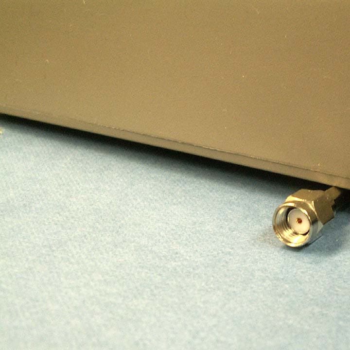
Click to zoom
Application Details
- Equipment Class
- DTS - Digital Transmission System
- Date of Grant
- Mar 28, 2007
- Application Purpose
- Original Equipment
- Date of Application
- Mar 28, 2007
- Equipment Note
- Linux Gateway Transceiver
- Frequency Range
- 2405.00000000 - 2475.00000000
- Country
- United States
Documents & Files
Document Text
Text extracted from the exhibit documents filed with the FCC. Open a document above to read the original.
Users Manual
1 2 Information in this document, including URL and internet website references, is subject to change without notice. Complying with all applicable copyright laws is the responsibility of the user. Without limiting the rights under copyright, no part of this document may be reproduced, stored or introduced into a retrieval system, or transmitted in any for or by any means (electronic, mechanical, photocopying, recording or otherwise), or for any purpose, without the express written permission of Crane WMS. Crane WMS may have patents, patent applications, trademarks, copyrights or other intellectual property rights covering subject matter in this document. Except as expressly provided in any written license agreement from Crane WMS, the furnishing of this document does not give you any license to these patents, trademarks, copyrights, or other intellectual property. ©2007 Crane WMS. All right reserved. Crane WMS & VantedgePoint are registered trademarks of Signal Technology in the United States and other countries. 3 Table of Contents: SPECIFICATIONS............................................................................................ 4 REGULATORY INFORMATION.................................................................... 5 LIMITED WARRANTY..................................................................................... 5 WIRELESS GATEWAY..................................................................................... 6 SAFETY INFORMATION................................................................................ 6 Follow Instructions to Avoid Interference Problems...................6 Pacemakers............................................................................................6 Hearing Aids...........................................................................................6 CONTACT INFORMATION............................................................................ 6 4 Specifications 5 Regulatory Information This product has been tested and complies with the specifications for a Class B digital device, pursuant to Part 15 of the FCC Rules. These limits are designed to provide reasonable protection against harmful interference. This equipment generates, uses, and can radiate radio frequency energy and, if not installed and used according to the instructions, may cause harmful interference to radio communications. However, there is no guarantee that interference will not occur in a particular installation. If this equipment does cause harmful interference to radio or television reception, which is found by turning the equipment off and on, the user is encouraged to try to correct the interference by one or more of the following measures: o Reorient or relocate the receiving antenna o Increase the separation between the equipment or devices o Connect the interfering equipment to an outlet other than the VantedgePoint Linux Gateway FCC Radiation Exposure Statement: This equipment complies with FCC radiation exposure limits set forth for an uncontrolled environment. This equipment should be installed and operated with minimum distance 20cm between the radiator and your body. Caution: FCC approved RF operation of this equipment is permitted only with the approved antennas, cable and connectors provided with this product. Use of unauthorized antennas, modifications or attachments could damage the device and/or may result in your device not complying with local regulatory requirements in your country. FCC regulates that this product may be used with a 5.5 dBi (or less) Omni directional antennae or a 13 dBi (or less) directional antennae. User should only use antennas supplied by Crane WMS. FCC Notice: Changes or modifications to this device not expressly approved by the manufacturer could void the user’s authority to operate the equipment. For more details on legal combinations of power levels and antennas, contact Crane WMS. Limited Warranty 6 Wireless Gateway The seller warrants to the end user (Customer) that this hardware product will be free from defects in workmanship and materials, under normal use and service, for 1 year from the date of purchase from the seller or its authorized reseller. The seller’s sole obligation under this express warranty shall be, at the seller’s option and expense, to repair the defective product or part, deliver to Customer an equivalent product or part to replace the defective item, or if neither of the two foregoing options is reasonably available, The seller may, in its sole discretion, refund to the Customer the purchase price paid for the defective product. All products that are replaced will become the property of the seller. Replacement products may be new or reconditioned. Wireless Gateway Software The seller makes no warranty or representation that its software products will meet Customer’s requirements or work in combination with any hardware or software applications products provided by third parties, that the operation of the software products will be uninterrupted or error free, or that all defects in the software products will be corrected Safety Information 1. Do not use this apparatus near water. 2. Do not install near any heat sources such as radiators, heat registers, stoves, or other apparatus (including amplifiers) that produce heat. 3. Do not defeat the safety purpose of the polarized or grounding type plug. A polarized plug has two blades with one wider than the other. A grounding-type plug has two blades and a third grounding prong. The wide blade or the third prong is provided for your safety. If the provided plug does not fit into your outlet, consult an electrician for replacement of the obsolete outlet. 4. Protect the power cord from being walked on or pinched particularly at plugs, convenience receptacles, and the point where they exit from the apparatus. 5. Only use attachments/accessories specified by the manufacturer. 6. Refer all servicing to qualified service personnel. Servicing is requir…
Text truncated - open the document above for the full version.
Block Diagram
ARM MicroController SDRAM FLASH ETHERNET PHY RADIO EM250 24MHz LPFPA LNA 25MHz 32.768 kHz 14.7456MHz32.768 kHz REAL TIME CLK RS232 DB9 USB RJ45 TX RX SWITCH RP SMA Wireless Gateway Block Diagram 2405 MHz - 2475 MHz
Cover Letter(s)
1820 Preston Park Boulevard ▪ Suite 2800 ▪ Plano, TX 75093 Phone 972.964.5178 ▪ Fax 972.964.5968 ▪ Web Site http://www.craneae.com/wms February 20, 2007 August 24, 2005 Federal Communications Commission EQUIPMENT AUTHORIZATION BRANCH 7435 Oakland Mills Road Columbia, MD 21046 RE: Relation between Crane WMS and Signal Technology Corporation To Whom It May Concern: The business unit submitting this application is called Wireless Monitoring Solutions (WMS) and it is a division within a company called Signal Technology Corporation, a Delaware Corporation. In May 2003, Crane Company purchased all assets of Signal Technology Corporation making it a wholly-owned subsidiary of Crane. If you have any additional questions or require additional clarification, please contact the undersigned at (972) 964-5789 at your convenience. Sincerely, Charlie Stuewe Vice President & General Manager Signal Technology WMS
Cover Letter(s)
1820 Preston Park Boulevard ▪ Suite 2800 ▪ Plano, TX 75093 Phone 972.964.5178 ▪ Fax 972.964.5968 ▪ Web Site http://www.craneae.com/wms January 29, 2007 August 24, 2005 Federal Communications Commission EQUIPMENT AUTHORIZATION BRANCH 7435 Oakland Mills Road Columbia, MD 21046 To Whom It May Concern: Signal Technology WMS hereby authorizes Nemko to act as our agent in the preparation of this application for equipment certification of the Wireless Gateway, model LG2400. APPLICANT ANTI-DRUG ABUSE CERTIFICATION: In signing this letter, Applicant certifies that, in the case of an individual applicant, he or she is not subject to a denial of federal benefits, that includes: FCC benefits, pursuant to Section 5301 of the Anti-Drug Abuse Act of 1988, 21 U.S.C. 853(a), or, in the case of a non-individual applicant. No party to the application is subject to a denial of federal benefits, that includes FCC benefits, pursuant to that section. For the definition of a “party” for these purposes, see 47 CFR 1.2002(b). Sincerely, Charlie Stuewe Vice President & General Manager Signal Technology WMS
Cover Letter(s)
1820 Preston Park Boulevard ▪ Suite 2800 ▪ Plano, TX 75093 Phone 972.964.5178 ▪ Fax 972.964.5968 ▪ Web Site http://www.craneae.com/wms February 7, 2007 Federal Communications Commission EQUIPMENT AUTHORIZATION BRANCH 7435 Oakland Mills Road Columbia, MD 21046 RE: CONFIDENTIALITY REQUEST FOR MODEL #: LG2400 FCC ID : S2ZLG2400 To Whom It May Concern: The following information is to be held confidential pursuant of 47 CFR Part 0 §0.459 and Section 552(b)(4) of the Freedom of Information Act, because the information provided contains trade secrets and proprietary. If made public, the information might be used to the disadvantage of the applicant in the market place. • Schematics • VantedgePoint_LinuxGateway_DataSheet.pdf • Bill of Materials (Parts List) Sincerely, Charlie Stuewe Vice President & General Manager Signal Technology WMS
RF Exposure Info
Prediction of MPE limit at a given distance Equation from page 18 of OET Bulletin 65, Edition 97-01 where:S = power density P = power input to the antenna G = power gain of the antenna in the direction of interest relative to an isotropic radiator R = distance to the center of radiation of the antenna Maximum peak output power at antenna input terminal:21.60(dBm) Maximum peak output power at antenna input terminal:144.5439771(mW) Antenna gain(typical):13(dBi) Maximum antenna gain:19.95262315(numeric) Time Averaging:100(%) Prediction distance:20(cm) Prediction frequency:2475(MHz) MPE limit for uncontrolled exposure at prediction frequency:1(mW/cm^2) Power density at prediction frequency:0.573760(mW/cm^2) Margin of compliance:-2.4(dB) 2 4R PG S π =
Test Report
Nemko Test Report: 2087RUS1 Applicant: Crane Co WMS 1820 Preston Park Blvd Suite 2800 Plano, TX 75093 USA Equipment Under Test: LG2400 (E.U.T.) In Accordance With: FCC Part 15, Subpart C, 15.247 Digital Transmission System Transmitter Tested By: Nemko USA, Inc. 802 N. Kealy Lewisville, Texas 75057-3136 TESTED BY: DATE: 17 January 2007 David Light, senior Wireless Engineer APPROVED BY: DATE: 17 January 2007 Kevin Rose Wireless Engineer Number of Pages: 38 Nemko USA, Inc. FCC PART 15, SUBPART C Digital Transmission Systems EQUIPMENT: LG2400 Test Report No.: 2087RUS1 Page 2 of 38 Table of Contents SECTION 1. SUMMARY OF TEST RESULTS 3 SECTION 2. EQUIPMENT UNDER TEST (E.U.T.) 5 SECTION 3. POWERLINE CONDUCTED EMISSIONS 7 SECTION 4. OCCUPIED BANDWIDTH 10 SECTION 5. MAXIMUM PEAK OUTPUT POWER 13 SECTION 6 SPURIOUS EMISSIONS AT ANTENNA TERMINALS 16 SECTION 7. RADIATED EMISSIONS 19 SECTION 8. PEAK POWER SPECTRAL DENSITY 24 SECTION 9. TEST EQUIPMENT LIST 27 ANNEX A - TEST DETAILS 28 ANNEX B - TEST DIAGRAMS 36 Nemko USA, Inc. FCC PART 15, SUBPART C Digital Transmission Systems EQUIPMENT: LG2400 Test Report No.: 2087RUS1 Page 3 of 38 Section 1. Summary of Test Results Manufacturer: Crane Co WMS Model No.: LG2400 Serial No.: 2006112100011 General: All measurements are traceable to national standards. These tests were conducted on a sample of the equipment for the purpose of demonstrating compliance with Part 15, Subpart C, Paragraph 15.247 for Digital Transmission Systems. Radiated tests were conducted is accordance with ANSI C63.4-2003. Radiated emissions are made on an open area test site. A description of the test facility is on file with the FCC. New Submission Production Unit Class II Permissive Change Pre-Production Unit THIS TEST REPORT RELATES ONLY TO THE ITEM(S) TESTED. THE FOLLOWING DEVIATIONS FROM, ADDITIONS TO, OR EXCLUSIONS FROM THE TEST SPECIFICATIONS HAVE BEEN MADE. See “ Summary of Test Data”. Nemko USA Inc. authorizes the above named company to reproduce this report provided it is reproduced in its entirety and for use by the company’s employees only. Any use which a third party makes of this report, or any reliance on or decisions to be made based on it, are the responsibility of such third parties. Nemko USA Inc. accepts no responsibility for damages, if any, suffered by any third party as a result of decisions made or actions based on this report. This report applies only to the items tested. Nemko USA, Inc. FCC PART 15, SUBPART C Digital Transmission Systems EQUIPMENT: LG2400 Test Report No.: 2087RUS1 Page 4 of 38 Summary Of Test Data NAME OF TEST PARA. NO. RESULT Powerline Conducted Emissions 15.207(a) Complies Minimum 6 dB Bandwidth 15.247(a)(2) Complies Maximum Peak Power Output 15.247(b)(3) Complies Spurious Emissions (Antenna Conducted) 15.247(d) Complies Spurious Emissions (Restricted Bands) 15.247(d)/15.209(a) Complies Peak Power Spectral Density 15.247(e) Complies Footnotes: Nemko USA, Inc. FCC PART 15, SUBPART C Digital Transmission Systems EQUIPMENT: LG2400 Test Report No.: 2087RUS1 Page 5 of 38 Section 2. Equipment Under Test (E.U.T.) General Equipment Information Frequency Band (MHz): 902-928 2400-2483.5 5725-5850 Operating Frequency of Test Sample: 2405 to 2475 MHz Channel Spacing: 5 MHz User Frequency Adjustment: Software controlled Nominal Voltage: 8-30 Vdc Antenna Type(s): 5.5 dBi Omni or 13 dBi Directional Antenna Connector: Reverse polarity SMA Nemko USA, Inc. FCC PART 15, SUBPART C Digital Transmission Systems EQUIPMENT: LG2400 Test Report No.: 2087RUS1 Page 6 of 38 Description of EUT Gateway for a wireless ZigBee network System Diagram Nemko USA, Inc. FCC PART 15, SUBPART C Digital Transmission Systems EQUIPMENT: LG2400 Test Report No.: 2087RUS1 Page 7 of 38 Section 3. Powerline Conducted Emissions NAME OF TEST: Powerline Conducted Emissions PARA. NO.: 15.207(a) TESTED BY: David Light DATE: 17 January 2007 Test Results: Complies. Measurement Data: See attached plots. Measurement Uncertainty: +/- 1.7 dB Test Equipment Used: 1663-1652-704-1188-674 Test Conditions 23ºC 42% RH Power adapter: Phihong PSA15-120P Nemko USA, Inc. FCC PART 15, SUBPART C Digital Transmission Systems EQUIPMENT: LG2400 Test Report No.: 2087RUS1 Page 8 of 38 Test Data – Powerline Conducted Emissions L1 Peak L1 Peak Ref 97.2 dBμV Offset 10.2 dB A LVL Att 0 dB * 85 kHz/Start 150 kHzStop 1 MHz * RBW 10 kHz VBW 30 kHz SWT 10 ms 1 PK VIEW 0 10 20 30 40 50 60 70 80 90 1 Marker 1 [T1 ] 54.30 dBμV 150.000000000 kHz LIMIT CHECK PASS C22BAVG Date: 18.JAN.2007 09:15:12 Ref 97.2 dBμV Offset 10.2 dB A LVL Att 0 dB * 2.985 MHz/Start 150 kHzStop 30 MHz * RBW 10 kHz VBW 30 kHz SWT 300 ms 1 PK VIEW 0 10 20 30 40 50 60 70 80 90 1 Marker 1 [T1 ] 54.31 dBμV 150.000000000 kHz LIMIT CHECK PASS C22BAVG Date: 18.JAN.2007 09:14:03 Nemko USA, Inc. FCC PART 15, SUBPART C Digital Transmission Systems EQUIPMENT: LG2400 Test Report No.: 2087RUS1 Page 9 of 38 Test Data – Powerline Conducted Emissions L2 Peak L2 Peak Ref 97.2 dBμV Offset 10.2 dB A LVL Att 0 dB * 15 kHz/Start 150 kHzStop 300 kHz * RBW 10 kHz SWT 2.5 ms VBW 30 kHz 1 PK VIEW 0 10 20 30 40 50 60 70 80 90 1 Marker 1 [T1 ] 55.86 dBμV 150.000000000 kHz LIMIT CHECK PASS C22BAVG Date: 18.JAN.2007 09:18:14 Ref 97.2 dBμV Offset 10.2 dB A LVL Att 0 dB * * RBW 10 kHz VBW 30 kHz SWT 300 ms Center 15.075 MHzSpan 29.85 MHz2.985 MHz/ *1 PK VIEW 0 10 20 30 40 50 60 70 80 90 1 Marker 1 [T1 ] 55.57 dBμV 150.000000000 kHz LIMIT CHECK PASS C22BAVG Date: 18.JAN.2007 09:23:35 Nemko USA, Inc. FCC PART 15, SUBPART C Digital Transmission Systems EQUIPMENT: LG2400 Test Report No.: 2087RUS1 Page 10 of 38 Section 4. Occupied Bandwidth NAME OF TEST: Occupied Bandwidth PARA. NO.: 15.247(a)(2) TESTED BY: David Light DATE: 14 January 2007 Test Results: Complies. Measurement Data: See 6 dB BW plot Measured 6 dB bandwidth: 1.57 MHZ MAXIMUM Channel Separation: 5 MHZ Test Conditions: 24 %RH 32 °C Measurement Uncertainty: +/-1x10 -7 ppm Test Equipment Used: 1464-1082-1472 Nemko USA, Inc. FCC PA…
Text truncated - open the document above for the full version.
Test Setup Photos
Photos – Powerline Conducted Emissions Front Side
Contact Information
Applicant
Magnus Aronsson(Engineer)
Technical Contact
Non-Technical Contact
Nemko USA, Inc.Christine Taylor
[email protected]972-436-9600
Test Firm
Nemko USA, Inc.Tom Tidwell
Technical Specifications
| # | Rule Parts | Frequency Range | Power Output |
|---|---|---|---|
| 1 | 15C | 2.40 GHz - 2.48 GHz | 144.50 mW |
Other Applications from Signal Technology Corporation
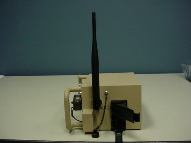
S2ZM-100
May 20, 2007Maestro Gateway Wireless Communications Bridge
Equipment Class
DTS - Digital Transmission System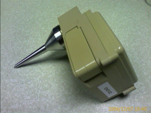
S2ZMO-1045
May 20, 2007MicroObserver Sensor Node
Equipment Class
DTS - Digital Transmission SystemS2Z1-51001EX
Sep 19, 2005Valve Watch Transceiver
Equipment Class
DSS - Part 15 Spread Spectrum Transmitter