S2ZM-100Maestro Gateway Wireless Communications Bridge
Signal Technology Corporation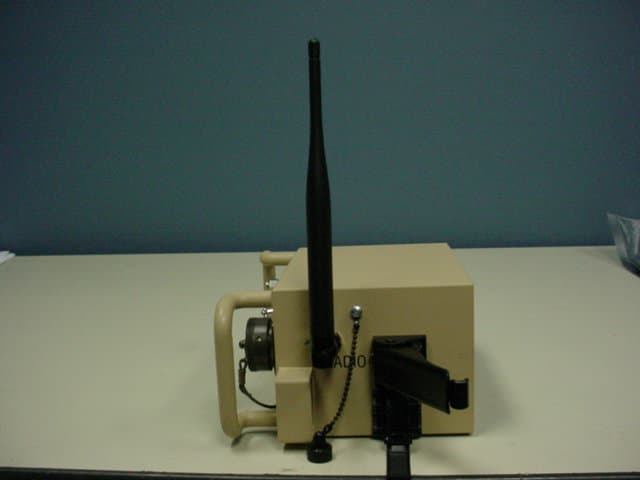
Click to zoom
Application Details
- Equipment Class
- DTS - Digital Transmission System
- Date of Grant
- May 20, 2007
- Application Purpose
- Original Equipment
- Date of Application
- Apr 10, 2007
- Equipment Note
- Maestro Gateway Wireless Communications Bridge
- Frequency Range
- 2404.00000000 - 2479.00000000
- Country
- United States
Documents & Files
Document Text
Text extracted from the exhibit documents filed with the FCC. Open a document above to read the original.
Users Manual
MicroObserver Unattended Ground Sensor System PRELIMINARY Users Manual Models M-100 & MO-1045 ITAR NOTICE This product and/or its technical data are export controlled by the U.S. State Department and covered by the International Traffic in Arms Regulations (ITAR). It may not be exported or transferred to any foreign person in the United States or abroad, except as authorized by the U.S. Department of State or the ITAR. Violators of these export laws are subject to severe civil and criminal penalties. 2 FCC Information Note: This equipment has been tested and found to comply with the limits for a Class A digital device, pursuant to Part 15 of the FCC. rules. These limits are designed to provide reasonable protection against harmful interference when the equipment is operated in a commercial environment. This equipment generates, uses, and can radiate radio frequency energy and, if not installed and used in accordance with the instruction manual, may cause harmful interference to radio communications. Operation of this equipment in a residential area is likely to cause harmful interference, in which case, the user will be required to correct the interference at his own expense. Caution: FCC approved RF operation of this equipment is permitted only with the approved antennas, cable and connectors provided with this product. FCC Notice: Changes or modifications to this device not expressly approved by the manufacturer could void the user’s authority to operate the equipment. FCC Radiation Exposure Statement This equipment complies with FCC radiation exposure limits for an uncontrolled environment. This equipment should be installed and operated with minimum distance of 20 cm between the antenna and all persons. 3 Table of Contents 1 INTRODUCTION...................................................................................................................................... 4 2 NETWORK ARCHITECTURE............................................................................................................... 4 3 SYSTEM COMPONENTS........................................................................................................................ 6 4 SYSTEM OPERATION ............................................................................................................................ 6 4.1 SENSOR START-UP PROCEDURE & DEPLOYMENT................................................................................ 6 4.2 MAESTRO GATEWAY START-UP AND DEPLOYMENT......................................................................... 10 4.3 OPERATOR TERMINAL....................................................................................................................... 11 4.4 COALESCING A WIRELESS SENSOR NETWORK.................................................................................. 12 4.5 REDEPLOYMENT OF SENSORS............................................................................................................ 13 4.6 RESETTING AND RE-COALESCING THE NETWORK. ............................................................................ 13 4.7 SHUTTING DOWN THE NETWORK...................................................................................................... 14 5 TROUBLE SHOOTING GUIDE ........................................................................................................... 14 4 1 Introduction The MicroObserver system is designed to provide a user with an easy-to-use, robust, scalable wireless network that detects intruding persons and vehicles. The system may be used in applications such as military reconnaissance missions, situational awareness scenarios, or for perimeter security similar to industrial plant security and border protection. The system consists of a remote gateway and multiple nodes which interface with a user- supplied, user-interface display. The nodes are deployed in the area where it is desired to monitor the presence of a person or vehicle. The gateway operates at a distance from the nodes, far enough away to be somewhat remote, but close enough to still communicate with them. Once deployed, the nodes and the gateway self-form a wireless network upon command. The nodes functions as sensors, monitoring detections and reporting their relative locations determined by means of Global Positioning System (GPS) to the user-interface display. 2 Network Architecture The MicroObserver System is a wireless three-tiered hub and spoke network consisting of sensors, hubs and remote gateways. The system hardware is homogenous, meaning any node can function as either a sensor, or a hub/sensor. There are no differences in either hardware or software of these nodes. Sensors are deployed in a pattern best suited to complete the mission objectives. The wireless connection is automatic and hubs are selected by the system based on their ability to communicate with all of the sensors in their area and the gateway. For larger areas, multiple hubs will be selected by the system. To enhance the energy management feature on the production system, hubs will rotate automatically within an area when the network is reformed. Figure 1 shows the basic system connectivity with the Gateway, Sensors and Hub/Sensors. 5 Figure 1 System Connectivity 6 3 System Components The MicroObserver system consists of two (2) primary pieces of hardware, the MicroObserver Sensor Node, MO-1045, and the Maestro Gateway, M-100. MicroObserver Sensor Nodes have two primary functions, to detect intruders and communicate with the network. The sensors employ seismic transducers to detect both dismounted personnel and vehicles (Vehicle Detection & Classification will be integrated in 2Q 2007). Seismic activity is measured and evaluated at the sensor with potential valid detections sent to the hub via a 2.4 GHz wireless connection which then relays the information wirelessly to the Maestro Gateway. The Maestro Gateway is the wireless communications bridge between the sensor field an…
Text truncated - open the document above for the full version.
Cover Letter(s)
1820 Preston Park Boulevard ▪ Suite 2800 ▪ Plano, TX 75093 Phone 972.964.5178 ▪ Fax 972.964.5968 ▪ Web Site http://www.craneae.com/wms March 16, 2007 Federal Communications Commission EQUIPMENT AUTHORIZATION BRANCH 7435 Oakland Mills Road Columbia, MD 21046 RE: CONFIDENTIALITY REQUEST FOR MODEL #: M-100 AND FCC ID #: S2ZM-100 To Whom It May Concern: The following information is to be held permanently confidential pursuant sections 0.457 and 0.459 of CFR 47 and Section 552(b)(4) of the Freedom of Information Act, because the information provided contains trade secrets and proprietary information. If made public, the information might be used to the disadvantage of the applicant in the market place. The information provided is also restricted under International Traffic in Arms Regulation (ITAR). Items which, due to ITAR, are requested to be held permanently confidential (other than the exhibits which can normally be held confidential) are: • Internal Printed Circuit Board Photographs • Test Report • Block Diagram • Housing Drawing Items which are requested to be held under normal permanent confidentiality are: • Schematics • Block Diagram • Bills of Materials (Parts Lists) Sincerely, Charlie Stuewe Vice President & General Manager Signal Technology WMS
Cover Letter(s)
1820 Preston Park Boulevard ▪ Suite 2800 ▪ Plano, TX 75093 Phone 972.964.5178 ▪ Fax 972.964.5968 ▪ Web Site http://www.craneae.com/wms March 16, 2007 Federal Communications Commission EQUIPMENT AUTHORIZATION BRANCH 7435 Oakland Mills Road Columbia, MD 21046 RE: CONFIDENTIALITY REQUEST FOR MODEL #: M-100 AND FCC ID #: S2ZM-100, and CONFIDENTIALITY REQUEST FOR MODEL #: MO-1045 AND FCC ID #: S2ZMO-1045 To Whom It May Concern: Pursuant to Rule CFR 47 Part 0.457, the following justification for the request for confidentiality is submitted. The items requested to be held permanently confidential (other than the exhibits which can normally be held confidential) are: • Internal Printed Circuit Board Photographs • Test Report • Block Diagram • Housing Drawing The subject equipments are designated by the Directorate of Defense Trade Controls as controlled items on the US Munitions List, under section XI (c) components as related to section XI (a), defense electronics. As such, all technical information (including internal photographs, test reports, block diagrams and component drawings) are subject to the International Trafficking in Arms Regulations (ITAR). Therefore, technical information concerning these equipments can not be released to the public without prior approval from the U.S. Department of State. Sincerely, Charlie Stuewe Vice President & General Manager Signal Technology WMS
ID Label/Location Info
BOTTOM
RF Exposure Info
Prediction of Maximum Permissible Exposure Equation from page 18 of OET Bulletin 65, Edition 97-01 where: S = power density P = power input to the antenna G = directional power gain of the antenna relative to an isotropic radiator R = distance to the center of radiation of the antenna Max. peak output power at antenna terminal(dBm):13.11 Max. peak output power at antenna terminal(mW):20.464 Antenna gain for prediction(dBi):5.5 Maximum antenna gain(numeric):3.5481339 Duty Cycle(%):100 Prediction distance(cm):20 Prediction frequency(MHz):2450 Limit for uncontrolled exposure(mw/cm²): 1.000 S(mw/cm²) = :0.014 2 4 PG S RΠ =
Test Report
FCC Home | Search | Updates | E-Filing | Initiatives | For Consumers | Find People Office of Engineering and Technology FCC > FCC E-filing > Inquiry System Home Page > Inquiry Confirmation FCC Site Map OET Home Page Site Options Knowledge DataBase Search Detail Criteria Search Submit An Inquiry Reply to an Inquiry Response Category List FAQ Search View Instructions Related Sites Equipment Authorization System (EAS) Telecommunications Certification Bodies (TCB) Your inquiry has been submitted to the Laboratory Division of the FCC Office of Engineering and Technology. You will receive a response within two business days. Please be sure to retain the inquiry tracking number displayed for future reference and questions concerning the status of this inquiry. Inquiry Tracking Number: 513967 Date of Submission: 02/20/2007 Subject: Request for Confidentiality Question: If a product falls under the ITAR(International Traffic in Arms Regulations), which requires that no technical information about can be made available to any foreign person in the US or abroad, may the materials that would normally not be eligible for withholding from public view be held confidential? The nature of this device is such that it will always be distributed under ITAR regulations. Please send any comments or suggestions for this site to OET Systems Support Federal Communications Commission 445 12th Street, SW Washington, DC 20554 More FCC Contact Information... Phone: 888-CALL-FCC (225-5322) TTY: 888-TELL-FCC (835-5322) Fax: 202-418-0232 E-mail: [email protected] - Privacy Policy - Web Policies & Notices - Customer Service Standards - Freedom of Information Act Page 1 of 1Inquiry Submission Confirmation 2/20/2007https://gullfoss2.fcc.gov/prod/oet/cf/kdb/forms/InquiryConfirmation.cfm
Contact Information
Applicant
Magnus Aronsson(Engineer)
Technical Contact
NTS CorporationTom Tidwell
[email protected]972-509-2566
1701 E. Plano Parkway · Plano, Texas · United States
Non-Technical Contact
NTS CorporationTom Tidwell
[email protected]972-509-2566
Test Firm
National Technical Systems (NTS)John Ngo
Technical Specifications
| # | Rule Parts | Frequency Range | Power Output |
|---|---|---|---|
| 1 | 15C | 2.40 GHz - 2.48 GHz | 20.00 mW |
Other Applications from Signal Technology Corporation
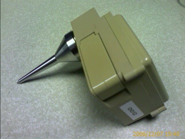
S2ZMO-1045
May 20, 2007MicroObserver Sensor Node
Equipment Class
DTS - Digital Transmission System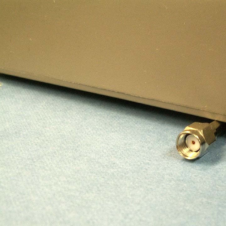
S2ZLG2400
Mar 28, 2007Linux Gateway Transceiver
Equipment Class
DTS - Digital Transmission SystemS2Z1-51001EX
Sep 19, 2005Valve Watch Transceiver
Equipment Class
DSS - Part 15 Spread Spectrum Transmitter