S3KTO41XXLTE Outdoor CPE
Global Telecom Corp
Click to zoom
Application Details
- Equipment Class
- DTS - Digital Transmission System
- Date of Grant
- May 25, 2021
- Application Purpose
- Original Equipment
- Date of Application
- May 25, 2021
- Equipment Note
- LTE Outdoor CPE
- Frequency Range
- 2412.00000000 - 2462.00000000
- Company
- Global Telecom Corp
- Country
- United States
Documents & Files
Document Text
Text extracted from the exhibit documents filed with the FCC. Open a document above to read the original.
Users Manual
TITAN4000 LTE Outdoor CPE Quick User Guide V1.0 2 PLEASE READ THESE SAFETY PRECAUTIONS! FCC Radiation Exposure Statement: This equipment complies with FCC radiation exposure limits set forth for an uncontrolled environment. This equipment should be installed and operated with minimum distance 20cm between the radiator & your body. FCC Warning This device complies with Part 15 of the FCC Rules. Operation is subject to the following two conditions: (1) This device may not cause harmful interference, and (2) this device must accept any interference received, including interference that may cause undesired operation. NOTE 1: This equipment has been tested and found to comply with the limits for a Class B digital device, pursuant to part 15 of the FCC Rules. These limits are designed to provide reasonable protection against harmful interference in a residential installation. This equipment generates uses and can radiate radio frequency energy and, if not installed and used in accordance with the instructions, may cause harmful interference to radio communications. However, there is no guarantee that interference will not occur in a particular installation. If this equipment does cause harmful interference to radio or television reception, which can be determined by turning the equipment off and on, the user is encouraged to try to correct the interference by one or more of the following measures: - Reorient or relocate the receiving antenna. - Increase the separation between the equipment and receiver. - Connect the equipment into an outlet on a circuit different from that to which the receiver is connected. - Consult the dealer or an experienced radio/TV technician for help. NOTE 2: Any changes or modifications to this unit not expressly approved by the party responsible for compliance could void the user's authority to operate the equipment. 3 1. Overview The TITAN4000 is highly innovative and patented LTE outdoor CPE product designed to enable quick and easy LTE fixed data service deployment for residential and SOHO customers. It provides high speed LAN services to end users who need both bandwidth and multi-media data service in enterprise or home. It can also be used to support wireless fall back service. 1.1. User Interface Specification Model Description & User Interface TITAN4000 - 1 RJ45 10/100/1000M LAN port - SYS, MOD, SIM, ETH, Wi-Fi, RF (5 Signal intensity LEDs) - PoE DC 48V, Power < 18 Watts (Average) - Dimensions: 300 mm (L) × 290 mm (W) × 97 mm (D) - Weight: <5Kg - Operating Temperature: -40°C to 55°C - Storage Temperature: -40°C to 85°C 4 2. Getting Started 2.1. Packing list and CPE Unit Upon receiving the product, please unpack the product package carefully. Each product is shipped with the following items: Table 2-1 Packing List Products Quantity CPE Unit 1 Clamp 2 Mounting brackets 1 PoE Adapter 1 Power cord 1.5M 1 Quick user guide 1 If you find any of the items missed, please contact your local distributor immediately. 2.2. Installing the Equipment Open the SIM card cover, insert the SIM card and connected the ETH cable. The user should use SFTP CAT5E Ethernet cable and connect to the appropriate LAN port 5 Mounting Bracket Using clamps to fixed. 6 Device logic connection LED Display LED Function Description SYS System run indicator Solid green – Device is in normal operation. MOD WAN port status OFF – NO wireless network access. Solid Green – WAN data transmission in progress SIM SIM card indicator Light is on – SIM card state is ready, Blinking Green – SIM card is error. ETH LAN port status Solid Green – LAN port is up. Blinking Green –LAN port in working. Wi-Fi Wi-Fi indicator Light is on –Wi-Fi is on. RF (5LEDs) RF Signal Strength 5 level signal strengths indication by 5 green LEDs. 1st Green LED: -115dBm < RSRP 2nd Green LED: -115dBm <= RSRP < -105dBm 3rd Green LED: -105dBm <= RSRP < -95dBm 4th Green LED: -95dBm <= RSRP < -85dBm 5th Green LED: -85 <= RSRP 7 3. Managing the CPE Device 3.1. WEB Login User can access the dongle management GUI using a Web browser from a local PC connected to device LAN port. The user should ensure that the connected PC have acquired IP address via DHCP from the device. After IP connectivity is established between the PC and window CPE device, the user may launch a Web browser and specify Http://192.168.0.1 in the address bar, the default home page will appear. Note the default password is “admin”. 3.2. System configuration DMZ This menu allows user to configure the DMZ setting for CPE in router mode. Web server, Telnet/SSH and Ping Service port can be exempted from DMZ mapping if required. By enabling DMZ option will make the specified local LAN host (DMZ IP) exposed to Internet. 8 Security This page allows user to configure the security setting. Applications This menu allows user to configure the port forwarding rules for the CPE in router mode. 9 Maintenance This page allows user to update the device firmware version, rest the device to factory setting and reboot the device. 4. Troubleshooting Q1: My PC cannot connect to the CPE. Check the PoE adapter LED is on and your PC LAN port is working. Q2: My CPE networking is not working properly. Check and make sure you are within LTE coverage. Q3: Unable to connect internet while the device is already connected to LTE network. Check and verify your computer has the ETH adapter installed and enabled. Unplug the PC Lan port and reconnect again if required.
Attestation Statements
Global Telecom Corp 17901 Von Karman Ave, Suite 600, Irvine, California 92614 United States Federal Communications Commission Authorization and Evaluation Division 1435 Oakland Mills Road Columbia, MD 21046 Date: 2021-05-18 SUBJECT: FCC Application for FCC ID: S3KTO41XX To Whom It May Concern: I, the undersigned, hereby states this equipment has been tested and found to comply with the limits for a Class B digital device, pursuant to part 15 of the FCC Rules, and will apply the Supplier's Declaration of Conformity procedure to Part 15 Class B Digital Device. I understand the following FCC requirements: 1. Devices subject to the SDoC procedure are required to be tested to show compliance with the FCC technical regulations by a recognized accredited testing laboratory. The testing laboratory must be accredited by a Commission approved accreditation body or designated under the terms of a government-to-government Mutual Recognition Agreement (MRA). A listing of those accredited testing laboratories that have been recognized by the Commission is published on the FCC Webpage: https://apps.fcc.gov/oetcf/eas/reports/TestFirmSearch.cfm (Select the "accredited" option to search for FCC recognized accredited test firms.) 2. Pt 2.1077 contains the list of information that must be included in the Supplier's Declaration of Conformity, which must be supplied with each product sold. The SDoC compliance info shall be included in the User’s Manual or as a separate sheet. The info must contain the name, address, and phone number of the responsible party, which must be located within the United States. According to 2.909(b), the responsible party is either the Manufacturer or if the product is imported the Importer. Regards, Global Telecom Corp ------------------------------- (Ahmad Malkawi) (Sr. Vice President Business Development)
Cover Letter(s)
Global Telecom Corp 17901 Von Karman Ave, suite 600, Irvine, California, 92614, United States -------------------------------------------------------------------------------- (FCC ID : S3KTO41XX) POWER OF ATTORNEY DATE: 2021-05- 18 Federal Communications Commission Authorization and Evaluation Division 7435 Oakland Mills Road Columbia, MD 21046 To Whom It May Concern: We, the undersigned, hereby authorize Waltek Testing Group (Shenzhen) Co., Ltd. Jandy So on our behalf, to apply to the Federal Communications Commission on our equipment. Any and all acts carried out by Waltek Testing Group (Shenzhen) Co., Ltd. Jandy So on our behalf shall have the same effect as acts of our own. This is to advise that we are in full compliance with the Anti-Drug Abuse Act. We, Global Telecom Corp are not subject to a denial of federal benefits pursuant to Section 5301 of the Anti-Drug Act of 1988, 21 USC853a, and no party to the application is subject to a denial of federal benefits pursuant to that section. Sincerely, Global Telecom Corp ------------------------------- (Ahmad Malkawi) (Sr. Vice President Business Development)
Cover Letter(s)
Global Telecom Corp 17901 Von Karman Ave, suite 600 , Irvine 92614, California, United States --------------------------------------------------------------------------------------------------------------------- Date: 2021-05- 18 Federal Communications Commission Authorization and Evaluation Division 7435 Oakl and Mills Road Columbia, MD 21046 FCC ID: S3KTO41XX Confidentiality Request To whom it may concern, Pursuant to Sections 0.457 and 0.459 of the Commission’s Rules, we hereby request confidential treatment of the information accompanying this application as outli ned below: ☒Block Diagram☒Tune- Up Information ☒Operational Description☐Security Information ☒Schematics☐Software Defined Radio (SDR) Information ☒Parts List Th e above materials contain trade secrets and proprietary information not customarily released to the public. The public disclosure of these materials may be harmful to the applicant and provide unjustified benefits to its competitors. The applicant understands that pursuant to Section 0.457 of the Rules, disclosure of this application and all accompanying documentation will not be made before the date of the Grant for this application. Sincerely, Global Telecom Corp ------------------------------- (Ahmad Malkawi) (Sr. Vice President Business Development)
External Photos
Reference No.: WTX21X04032055W-1/2 Page 2 of 17 Waltek Testing Group (Shenzhen) Co., Ltd. Http://www.waltek.com.cn EXHIBIT 2 - EUT EXTERNAL PHOTOGRAPHS EUT View 1 EUT View 2 Reference No.: WTX21X04032055W-1/2 Page 3 of 17 Waltek Testing Group (Shenzhen) Co., Ltd. Http://www.waltek.com.cn EUT View 3 EUT View 4 Reference No.: WTX21X04032055W-1/2 Page 4 of 17 Waltek Testing Group (Shenzhen) Co., Ltd. Http://www.waltek.com.cn EUT View 5 EUT View 6 Reference No.: WTX21X04032055W-1/2 Page 5 of 17 Waltek Testing Group (Shenzhen) Co., Ltd. Http://www.waltek.com.cn EUT View 7 EUT View 8
ID Label/Location Info
Reference No.: WTX21X04032055W-1/2 Page 1 of 17 Waltek Testing Group (Shenzhen) Co., Ltd. Http://www.waltek.com.cn ANNEX EXHIBIT 1 - PRODUCT LABELING Proposed FCC ID Label Forma Specifications: The label shall be securely affixed to a permanently attached part of the device, in a location where it is visible or easily accessible to the user, and shall not be readily detachable. The label shall be sufficiently durable to remain fully legible and intact on the device in all normal conditions of use throughout the device’s expected lifetime. Proposed Label Location on EUT FCC ID Label Location
Internal Photos
Reference No.: WTX21X04032055W-1/2 Page 6 of 17 Waltek Testing Group (Shenzhen) Co., Ltd. Http://www.waltek.com.cn EXHIBIT 3 - EUT INTERNAL PHOTOGRAPHS EUT Housing and Board View 1 EUT Housing and Board View 2 Reference No.: WTX21X04032055W-1/2 Page 7 of 17 Waltek Testing Group (Shenzhen) Co., Ltd. Http://www.waltek.com.cn Solder Board-Component View 1 Solder Board-Component View 2 Reference No.: WTX21X04032055W-1/2 Page 8 of 17 Waltek Testing Group (Shenzhen) Co., Ltd. Http://www.waltek.com.cn Solder Board-Component View 3 Solder Board-Component View 4
Internal Photos
Reference No.: WTX21X04032055W-1/2 Page 9 of 17 Waltek Testing Group (Shenzhen) Co., Ltd. Http://www.waltek.com.cn Solder Board-Component View 5 Solder Board-Component View 6 Reference No.: WTX21X04032055W-1/2 Page 10 of 17 Waltek Testing Group (Shenzhen) Co., Ltd. Http://www.waltek.com.cn Solder Board-Component View 7 Solder Board-Component View 8 Reference No.: WTX21X04032055W-1/2 Page 11 of 17 Waltek Testing Group (Shenzhen) Co., Ltd. Http://www.waltek.com.cn Solder Board-Component View 9 Solder Board-Component View 10
Internal Photos
Reference No.: WTX21X04032055W-1/2 Page 12 of 17 Waltek Testing Group (Shenzhen) Co., Ltd. Http://www.waltek.com.cn Solder Board-Component View 11 Solder Board-Component View 12 Reference No.: WTX21X04032055W-1/2 Page 13 of 17 Waltek Testing Group (Shenzhen) Co., Ltd. Http://www.waltek.com.cn Solder Board-Component View 13 Antenna View Reference No.: WTX21X04032055W-1/2 Page 14 of 17 Waltek Testing Group (Shenzhen) Co., Ltd. Http://www.waltek.com.cn Antenna View
RF Exposure Info
1. MAXIMUM PERMISSIBLE EXPOSURE (MPE) 1.1 General Information Client Information Applicant: Global Telecom Corp Address of applicant: 17901 Von Karman Ave, Suite 600, Irvine, California 92614 United States of America Applicant: Global Telecom Corp Address of applicant: 17901 Von Karman Ave, Suite 600, Irvine, California 92614 United States of America General Description of EUT: Product Name: LTE Outdoor CPE Trade Name: Global Telecom, TITAN Model No.: TITAN4000 Adding Model(s): / Rated Voltage: AC120V; POE DC48V FCC ID: S3KTO41XX Equipment Type: Fixed Technical Characteristics of EUT: Wi-Fi Support Standards: 802.11b, 802.11g, 802.11n Frequency Range: 2412-2462MHz for 802.11b/g/n(HT20) 2422-2452MHz for 802.11n(HT40) RF Output Power: Antenna 1: 16.66dBm (Conducted) Antenna 2: 16.36dBm (Conducted) Type of Modulation: DBPSK,BPSK,DQPSK,QPSK,16QAM,64QAM Quantity of Channels: 11 for 802.11b/g/n(HT20); 7 for 802.11n(HT40) Channel Separation: 5MHz Type of Antenna: Integral Antenna Antenna Gain: 3dBi 4G Support Networks: TDD-LTE Support Band: TDD-LTE Band 41 Uplink Frequency: TDD-LTE Band 41: Tx: 2496-2690MHz Downlink Frequency: TDD-LTE Band 41: Rx: 2496-2690MHz, RF Output Power: TDD-LTE Band 41: 24.20dBm, Type of Emission: TDD-LTE Band 41: 17M9G7D, 17M9W7D Type of Modulation: QPSK, 16QAM Antenna Type: Integral Antenna Antenna Gain: TDD-LTE Band 41: 12dBi 1.2 Standard Applicable According to §1.1307(b)(1) and KDB 447498 D01 General RF Exposure Guidance v06, system operating under the provisions of this section shall be operating in a manner that the public is not exposed to radio frequency energy level in excess limit for maximum permissible exposure. (a) Limits for Occupational / Controlled Exposure Frequency range (MHz) Electric Field Strength (E) (V/m) Magnetic Field Strength (H) (A/m) Power Density (S) (mW/cm 2 ) Averaging Times | E | 2 , | H | 2 or S (minutes) 0.3-3.0 614 1.63 (100)* 6 3.0-30 1842/f 4.89/f (900/f)* 6 30-300 61.4 0.163 1.0 6 300-1500 / / F/300 6 1500-100000 / / 5 6 (b) Limits for General Population / Uncontrolled Exposure Frequency range (MHz) Electric Field Strength (E) (V/m) Magnetic Field Strength (H) (A/m) Power Density (S) (mW/cm 2 ) Averaging Times | E | 2 , | H | 2 or S (minutes) 0.3-1.34 614 1.63 (100)* 30 1.34-30 824/f 2.19/f (180/f)* 30 30-300 27.5 0.073 0.2 30 300-1500 / / F/1500 30 1500-100000 / / 1 30 Note: f = frequency in MHz: * = Plane-wave equivalents power density 1.3 MPE Calculation Method S = (30*P*G) / (377*R 2 ) S = power density (in appropriate units, e.g., mw/cm 2 ) P = power input to the antenna (in appropriate units, e.g., mw) G = power gain of the antenna in the direction of interest relative to an isotropic radiator, the power gain factor is normally numeric gain. R = distance to the center of radiation of the antenna (in appropriate units, e.g., cm) 1.4 MPE Calculation Result Wi-Fi Maximum Tune-Up output power: 17(dBm) Maximum peak output power at antenna input terminal: 50.12 (mW) Prediction distance: >20(cm) Prediction frequency: 2412 (MHz) Antenna gain: 3(dBi) Directional gain (numeric gain): 2.00 The worst case is power density at prediction frequency at 20cm: 0.0199 (mw/cm 2 ) MPE limit for general population exposure at prediction frequency: 1 (mw/cm 2 ) 4G Maximum Tune-Up output power: 24.5(dBm) Maximum peak output power at antenna input terminal: 281.84 (mW) Prediction distance: >20(cm) Prediction frequency: 2593.0 (MHz) Antenna gain: 12 (dBi) Directional gain (numeric gain): 15.85 The worst case is power density at prediction frequency at 20cm: 0.8886 (mw/cm 2 ) MPE limit for general population exposure at prediction frequency: 1 (mw/cm 2 ) Mode for Simultaneous Multi-band Transmission Wi-Fi+ 4G The worst case is power density at prediction frequency at 20cm: 0.0199+0.8886=0.9085(mw/cm 2 ) MPE limit for general population exposure at prediction frequency: 1 (mw/cm 2 ) Result: Pass
Test Report
Waltek Testing Group (Shenzhen) Co., Ltd. Http://www.waltek.com.cn Page 1 of 90 TEST REPORT Reference No. .................... : WTX21X04032055W-2 FCC ID ................................ : S3KTO41XX Applicant ........................... : Global Telecom Corp Address ............................. : 17901 Von Karman Ave, Suite 600, Irvine, California 92614 United States of America Product Name ................... : LTE Outdoor CPE Test Model. ........................ : TITAN4000 Standards .......................... : FCC Part 15.247 Date of Receipt sample .... : Apr.12, 2021 Date of Test........................ : Apr.12, 2021 to May.17, 2021 Date of Issue ..................... : May.17, 2021 Test Result ......................... : Pass Remarks: The results shown in this test report refer only to the sample(s) tested, this test report cannot be reproduced, except in full, without prior written permission of the company. The report would be invalid without specific stamp of test institute and the signatures of compiler and approver. Prepared By: Waltek Testing Group (Shenzhen) Co., Ltd. Address: 1/F., Room 101, Building 1, Hongwei Industrial Park, Liuxian 2nd Road, Block 70 Bao'an District, Shenzhen, Guangdong, China Tel.: +86-755-33663308 Fax.: +86-755-33663309 Tested by: Reviewed By: Approved & Authorized By: Jason Su / Project Engineer Lion Cai / RF Manager Silin Chen / Manager Reference No.: WTX21X04032055W-2 Page 2 of 90 Waltek Testing Group (Shenzhen) Co., Ltd. Http://www.waltek.com.cn TABLE OF CONTENTS 1. GENERAL INFORMATION ................................................................................................................................... 4 1.1 PRODUCT DESCRIPTION FOR EQUIPMENT UNDER TEST (EUT) ............................................................................... 4 1.2 TEST STANDARDS ................................................................................................................................................... 5 1.3 TEST METHODOLOGY ............................................................................................................................................. 5 1.4 TEST FACILITY ....................................................................................................................................................... 5 1.5 EUT SETUP AND TEST MODE ................................................................................................................................. 6 1.6 MEASUREMENT UNCERTAINTY .............................................................................................................................. 7 1.7 TEST EQUIPMENT LIST AND DETAILS ..................................................................................................................... 8 2. SUMMARY OF TEST RESULTS ......................................................................................................................... 10 3. ANTENNA REQUIREMENT ................................................................................................................................ 11 3.1 STANDARD APPLICABLE ....................................................................................................................................... 11 3.2 EVALUATION INFORMATION ................................................................................................................................ 11 4. POWER SPECTRAL DENSITY ........................................................................................................................... 12 4.1 STANDARD APPLICABLE ....................................................................................................................................... 12 4.2 TEST SETUP BLOCK DIAGRAM ............................................................................................................................. 12 4.3 TEST PROCEDURE ................................................................................................................................................. 12 4.4 SUMMARY OF TEST RESULTS/PLOTS .................................................................................................................... 12 5. DTS BANDWIDTH ................................................................................................................................................. 13 5.1 STANDARD APPLICABLE ....................................................................................................................................... 13 5.2 TEST SETUP BLOCK DIAGRAM ............................................................................................................................. 13 5.3 TEST PROCEDURE ................................................................................................................................................. 13 5.4 SUMMARY OF TEST RESULTS/PLOTS .................................................................................................................... 13 6. RF OUTPUT POWER ............................................................................................................................................ 14 6.1 STANDARD APPLICABLE ....................................................................................................................................... 14 6.2 TEST SETUP BLOCK DIAGRAM ............................................................................................................................. 14 6.3 TEST PROCEDURE ................................................................................................................................................. 14 6.4 SUMMARY OF TEST RESULTS/PLOTS .................................................................................................................... 14 7. FIELD STRENGTH OF SPURIOUS EMISSIONS ............................................................................................. 15 7.1 STANDARD APPLIC…
Text truncated - open the document above for the full version.
Test Setup Photos
Reference No.: WTX21X04032055W-1/2 Page 15 of 17 Waltek Testing Group (Shenzhen) Co., Ltd. Http://www.waltek.com.cn EXHIBIT 4 - TEST SETUP PHOTOGRAPHS Conducted Emission Test Setup* Radiation Emission Test Setup (Below 30MHz) Reference No.: WTX21X04032055W-1/2 Page 16 of 17 Waltek Testing Group (Shenzhen) Co., Ltd. Http://www.waltek.com.cn Radiation Emission Test Setup (30MHz to 1GHz) Radiation Emission Test Setup (1GHz to 18GHz) Reference No.: WTX21X04032055W-1/2 Page 17 of 17 Waltek Testing Group (Shenzhen) Co., Ltd. Http://www.waltek.com.cn Radiation Emission Test Setup (Above 18GHz) * Means’ only test and setup for PART 15C. ***** END OF REPORT *****
Contact Information
Applicant
Ahmad Malkawi(Sr. Vice President Business Development)
Test Firm
Waltek Testing Group (Shenzhen) Co., Ltd.Jandy So
Technical Specifications
| # | Rule Parts | Frequency Range | Power Output |
|---|---|---|---|
| 1 | 15C | 2.41 GHz - 2.46 GHz | 46.30 mW |
Other Applications from Global Telecom Corp
S3K5GCPE1
Jul 17, 20245G Indoor CPE
Equipment Class
NII - Unlicensed National Information Infrastructure TX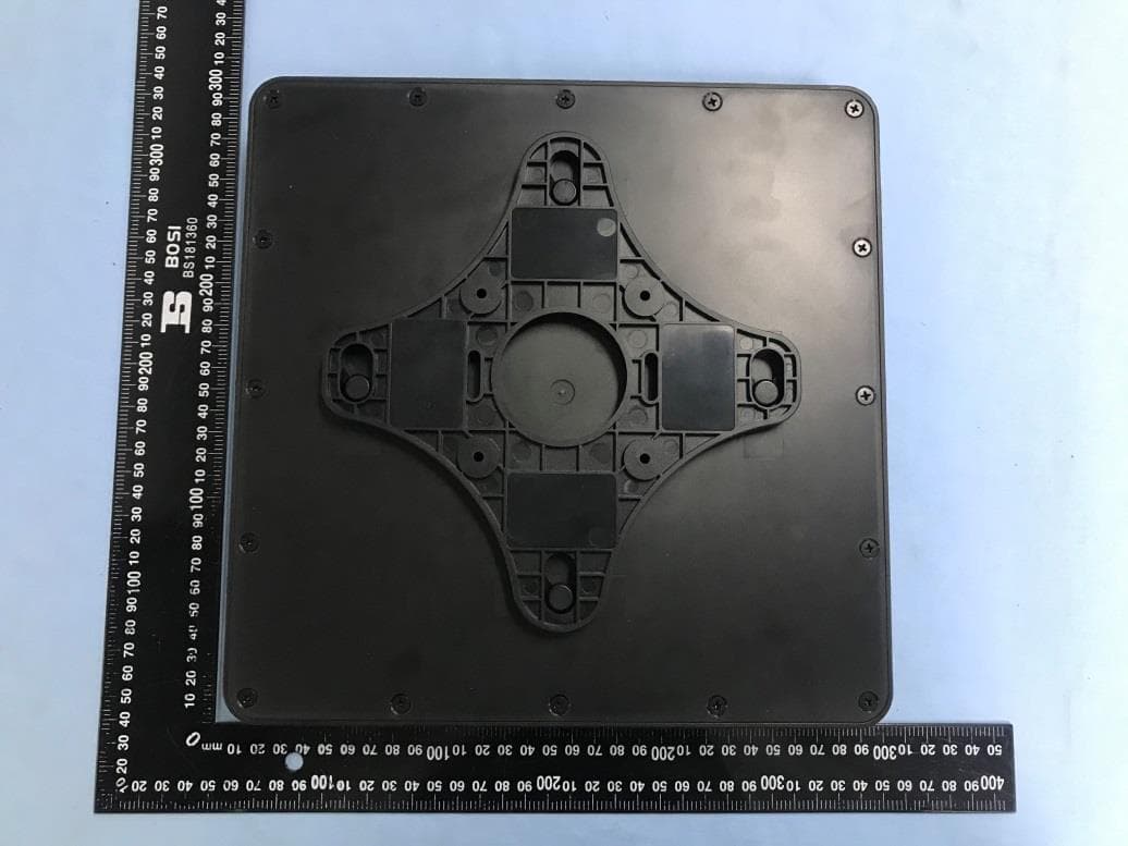
S3KG7243A
Mar 26, 2020LTE CPE
Equipment Class
PCB - PCS Licensed Transmitter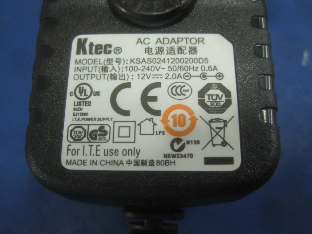
S3KSWC9200
Aug 01, 2013WIMAX/WIFI modem indoor/outdoor
Equipment Class
TNB - Licensed Non-Broadcast Station Transmitter