S490806SSR02Slope Stability Radar
GroundProbe Pty Ltd
Click to zoom
Application Details
- Equipment Class
- TNB - Licensed Non-Broadcast Station Transmitter
- Date of Grant
- Nov 05, 2006
- Application Purpose
- Original Equipment
- Date of Application
- Nov 05, 2006
- Equipment Note
- Slope Stability Radar
- Frequency Range
- 9552.50000000 - 9552.50000000
- Company
- GroundProbe Pty Ltd
- Country
- Australia
Documents & Files
Document Text
Text extracted from the exhibit documents filed with the FCC. Open a document above to read the original.
Cover Letter(s)
From: Rummel, Jeffrey [mailto:[email protected]] Sent: Friday, October 27, 2006 3:28 PM To: [email protected] Cc: Chris Jensen; [email protected] Subject: GroundProbe Pty Ltd. - Response to September 30, 2006 E-Mail Re: FCC ID: S490806SSR02, Assessment No.: AN06T6140, Notice#1 Mr. Harvey: In response to your e-mail dated September 30, 2006 ("September 30 E-Mail"), to Richard Hodgson of GroundProbe Pty Ltd. ("GroundProbe"), with respect to the above-referenced application ("Application"), the following is respectfully submitted: 1. Attached hereto is a file (SSRXAuthlet - Signed.pdf) containing the signed "Letter of Authorization" provided by GroundProbe authorizing undersigned counsel to submit the instant response, and the attached documents, on behalf of GroundProbe. A hard copy of the Letter of Authorization is forthcoming, and will be submitted to you upon receipt. 2. Also attached hereto is a file (SSRXSupp - signed.pdf) containing the signed "Supplemental Request for Confidentiality" ("Supplemental Request") provided by GroundProbe. As explained in the Supplemental Request, additional materials ("Additional Confidential Documents") are being submitted along with this transmittal in response to your September 30 E-Mail. Accordingly, the Supplemental Request is hereby submitted, pursuant to §0.457(d) (1) (ii) and 0.459 of the Commission's rules, to confirm GroundProbe's prior request for confidentiality with respect to the Original Confidential Documents (i.e., those identified in GroundProbe's original Confidentiality Request dated September 7, 2006) and the Additional Confidential Documents being submitted at this time. A hard copy of the Supplemental Request is forthcoming, and will be submitted to you upon receipt. 3. The following specific responses are provided in response to the September 30 E-Mail: Item 1 (Internal Photos) In response to the September 30 E-Mail, as part of the Additional Confidential Documents being submitted at this time, a new electronic file (SSR-X REB Internal Photos.doc), attached hereto containing photos of the SSR-X radar electronics box, is hereby submitted in support of the Application. Confidentiality is being requested with respect to the documents contained therein. This file shall replace the prior photo exhibit previously submitted in support of the Application. The prior photo exhibit remains confidential for the reasons previously stated, and as a result such file/documents should not be made available to the public. Item 2 (Schematics) In response to the September 30 E-Mail, as part of the Additional Confidential Documents being submitted at this time, a new electronic file (REB_Schematics_Submission2.pdf), attached hereto containing all schematics and block diagrams relevant to the SSR-X radar electronics box, is hereby submitted in support of the Application. Confidentiality is being requested with respect to the documents contained therein. This file shall replace the block diagrams previously submitted in support of the Application. The previously- submitted block diagrams remain confidential for the reasons previously stated, and as a result such file/documents should not be made available to the public. Item 3 (Test Method) In response to the September 30 E-Mail, the following is respectfully submitted: GroundProbe understands that the substitution method is the primary method to address radiated spurious emission compliance. However, as set forth at OET Website Publication Number 213318 (copy of Publication attached as part of file named "ANSI.pdf"), testing pursuant to ANSI C64.3 is permitted when "the initial measured field strength levels of the spurious emissions are more than 20 dB below" the 3 meter field strength limits equivalent to the EIRP limit. This issue was confirmed with CCS' Mike Kuo during the initial certification of the SSR system (see attached e-mail from Mike Kuo dated 5/12/2005 as part of file named ANSI.pdf). Further, we note that the use of the ANSI C63.4 test plan (in connection with the original certification of the SSR system last year) was also confirmed by CCS' Mike Heckrotte and the FCC's Steve Dayhoff at the commencement of the certification process. Because in this case the initial measured field strength levels of the spurious emissions were more than 20 dB below the 3 meter field strength limits equivalent to the EIRP limit, ANSI C63.4 was used in place of EIA/TIA 603B. This issue was generally referenced at the top of Page 13 of EMI Test Report dated 7/24/06. If any supplemental statements are necessary to confirm this issue, GroundProbe would be pleased to provide same. GroundProbe understands that the documents submitted in the attached file named ANSI.pdf are not subject to confidentiality. Item 4 (Test Report Photos) In response to the September 30 E-Mail, attached is a single bundled file (M060755_Cert_Tx EMC Technologies SSR-X Test Report Photos.pdf) containing the 5 photos shown in the EMC test report. GroundProbe understands that these documents are not subject to confidentiality. Item 5 ( Bandwidth/ Emissions Designator) In response to the September 30 E-Mail, the following is respectfully submitted: With respect to the determination of Necessary Bandwidth, the "96M5" was derived from the measured occupied bandwidth of the Radar as shown in the EMC Technologies EMI Test Report. With respect to the identification of the "P0N" emissions designator, it was determined that the SSR is characterized as P0N, as the radar carrier is not modulated by a modulating input signal channel. - With regard to the first symbol (type of modulation of the main carrier), the letter "P" was chosen. "P" represents a "sequence of unmodulated pulses". In this regard, the SSR-X system transmits a sequence of pulses which are unmodulated as the device uses no channelization. - With regard to the second symbol (nature of signal(s) modulating the main carrier), "0" was chosen. "0" represents "No …
Text truncated - open the document above for the full version.
ID Label/Location Info
FCC ID Label Format and Label Location 724714.DOC Sticker Details Manufacturer : Brady Part Number : PTL-31-486 Dimension : h25.4 x w38.1mm Sticker Type : Permanent Metallized Polyester Temperature Rating : Max 120 o C / 30 Days FCC ID: S490806SSR02 This device complies with Part 90 of the FCC Rules FCC ID Label – Fitted to antenna tripod
Test Report
EMC Technologies Pty Ltd reports apply only to the specific samples tested under stated test conditions. It is the manufacturer’s responsibility to assure that additional production units of this model are manufactured with identical electrical and mechanical components. EMC Technologies Pty Ltd shall have no liability for any deductions, inferences or generalisations drawn by the client or others from EMC Technologies Pty Ltd issued reports. This report shall not be used to claim, constitute or imply product endorsement by EMC Technologies Pty Ltd. The tests, calibrations or measurements covered by this document have been performed in accordance with NATA requirements which include the requirements of ISO/IEC 17025 and are traceable to national standards of measurement. This document shall not be reproduced, except in full. EMC Technologies Pty Ltd ABN 82 057 105 549 57 Assembly Drive Tullamarine Victoria Australia 3043 Ph: + 613 9335 3333 Fax: + 613 9338 9260 email: [email protected] EMI TEST REPORT for CERTIFICATION to FCC PART 90 FCC ID: S490806SSR02 Test Sample: Slope Stability Radar Model: Tested for: GroundProbe Pty Ltd Report Number: Report M060753_Cert_Tx Issue Date: 24 th July 2006 FCC ID: S490806SSR02 Report M060755_Cert_Tx, Page 2 of 14 This document shall not be reproduced, except in full. EMI TEST REPORT FOR CERTIFICATION to FCC Part 90 EMC Technologies Report No. Report M060753_Cert_Tx Issue Date: 24 th July 2006 CONTENTS 1 INTRODUCTION 4 2 GENERAL INFORMATION 5 2.1 Test Sample Description 5 2.2 Test sample configuration 5 2.3 Test Sample Block Diagram 6 2.4 Test Procedure 6 2.5 Test Conditions 6 2.6 Test Facility 6 2.7 Units of Measurements 8 2.8 Test Equipment Calibration 8 2.9 Ambients at OATS 8 3 RF MEASURMENTS 8 3.1 Power Output, Section 2.1046 8 3.2 Modulation Characteristic, Section 2.1047 9 3.3 Occupied Bandwidth, Section 2.1049 10 3.4 Conducted Spurious Emissions, Section 2.1051 10 3.5 Frequency Stability, Section 2.1055 11 4 RADIATED EMISSION MEASUREMENTS 12 4.1 Test Procedure 12 4.2 Calculation of Peak and Average Field Strength 12 4.3 Relation between field-strength and E.I.R.P. 12 4.4 Radiated Spurious, Section 2.1053 12 5 COMPLIANCE STATEMENT 13 FCC ID: S490806SSR02 Report M060755_Cert_Tx, Page 3 of 14 This document shall not be reproduced, except in full. EMI TEST REPORT FOR CERTIFICATION to FCC PART 90 Report Number: Report M060755_Cert_Tx Test Sample: Slope Stability Radar Model: SSR-X Manufacturer: GroundProbe Pty Ltd Address: 8 Hockings Street, South Brisbane QLD 4101 Phone: (617) 3010 8999 Fax: (617) 3010 8988 Contact: Richard Hodgson ([email protected]) FCC ID: S490806SSR02 Equipment Type: Intentional Radiator Tested for: GroundProbe Pty Ltd Address: 8 Hockings Street, South Brisbane QLD 4101 Phone: (617) 3010 8999 Fax: (617) 3010 8988 Responsible Party: Richard Hodgson Test Standards: FCC Part 90- Private Land Mobile Services Test Dates: Test Officers: Mark Mifsud Jorge Lara Melbourne Manager OATS Manager Attestation: I hereby certify that the device(s) described herein were tested as described in this report and that the data included is that which was obtained during such testing. Authorised Signatory: Mark Mifsud Melbourne Manager EMC Technologies Pty Ltd FCC ID: S490806SSR02 Report M060755_Cert_Tx, Page 4 of 14 This document shall not be reproduced, except in full. EMI TEST REPORT FOR CERTIFICATION to FCC PART 90 1 INTRODUCTION This report details the results of RF tests and measurements performed on the Slope Stability Radar (SSR). Test results were obtained using procedures in accordance with the following Federal Communications Commission (FCC) standards/regulations: The test sample complied with the requirements of: 1.1 Summary of Results FCC Part 90, Test Performed Result 2.1046 Power Output Noted 2.1047 Modulation Complied 2.1049 Bandwidth Complied 2.1051 Spurious Complied 2.1053 Spurious Complied 2.1055 Stability Complied 2.1057 Frequency Range Noted 2.202 Bandwidths Noted The measurement procedures used were in accordance with ANSI C63.4-2003 and OET Bulletin No. 65. The instrumentation conformed to the requirements of ANSI C63.2-1996. 1.2 Modifications by EMC Technologies No modifications were required. FCC ID: S490806SSR02 Report M060755_Cert_Tx, Page 5 of 14 This document shall not be reproduced, except in full. 2 GENERAL INFORMATION 2.1 Test Sample Description (as supplied by Client) The sample tested has the following specifications: a. Mean Transmitter Power: 60 mW b. Peak Transmitter Power: 60 mW c. Pulse Width: 2.884 seconds d. Pulse Repetition Frequency: 107.107 kHz e. Antenna Gain: 46 dBi f. Maximum EIRP: 25.8 dBW g. Lowest generated RF: 107.107 kHz h. Power Supply: 12V DC batteries charged intermittently by diesel generator. Universal AC input battery charger for backup. i. Temperature: -26 degrees to 55 degrees Centigrade Refer to Appendix C for further details. 2.2 Test sample configuration The SSR-X was transmitting continuously during the tests. FCC ID: S490806SSR02 Report M060755_Cert_Tx, Page 6 of 14 This document shall not be reproduced, except in full. Testing was performed with the SSR-X rotated around 3 orthogonal planes. The worst-case results are reported. Refer to Appendix B - Test Setup Photographs. 2.3 Test Sample Block Diagram Refer to Appendix C – Test Sample Block Diagram 2.4 Test Procedure Emissions measurements were performed in accordance with the procedures of ANSI C63.4- 2003. Radiated emissions tests were performed at a distance of 3 and 10 metres from the EUT. 2.5 Test Conditions The SSR-X was tested with the following test conditions: a. Standard Temperature and Humidity i. Temperature: +25°C ± 4° maintained. ii. Relative Humidity: 60% ± 10% observed. b. Standard Test Power Source i. Standard Test Voltage: 12.9 Vdc. c. Extreme Temperature i. High Temperature: + 55°C maintained. ii. Low Temperature: - -26 °C maintained. d. Extreme Voltage Conditions. i. Extreme High Supply Voltage 14.8 V …
Text truncated - open the document above for the full version.
Contact Information
Applicant
David Noon(VP Marketing & Technology)
Test Firm
EMC Technologies Pty. Ltd.Michael Evans
Technical Specifications
| # | Rule Parts | Frequency Range | Power Output | Emission | Tolerance |
|---|---|---|---|---|---|
| 1 | 90 | 9.55 GHz - 9.55 GHz | 60.00 mW | 96M5P0N | 0.0500000000 % |
Other Applications from GroundProbe Pty Ltd
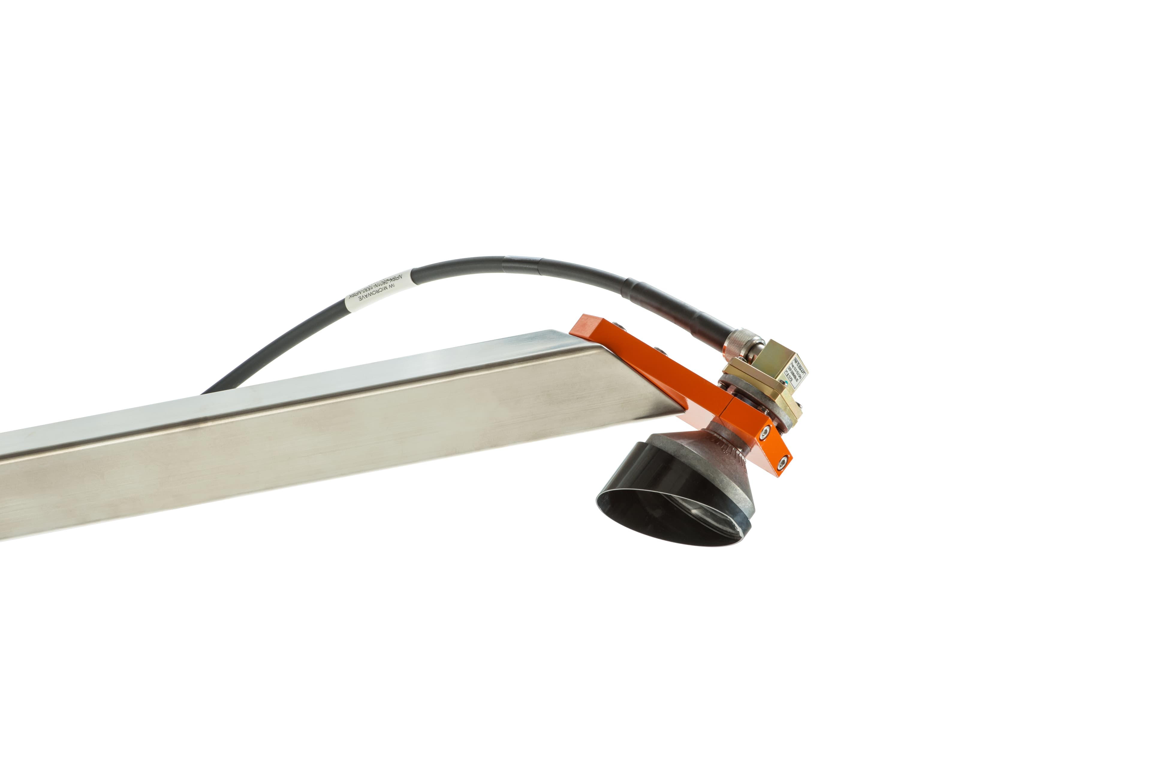
S491225S5SSRXT
Aug 19, 2026Slope Stability Radar Module
Equipment Class
TNB - Licensed Non-Broadcast Station Transmitter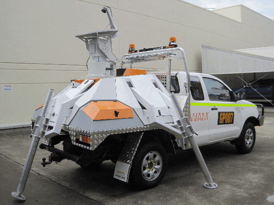
S491011SSR03
Nov 28, 2011Work Area Monitor
Equipment Class
TNB - Licensed Non-Broadcast Station Transmitter