S4CKC-9303ADIGITAL FM TRANSMITTER
Alligator Game Company Limited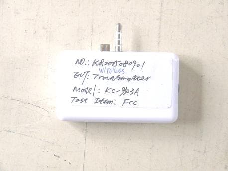
Click to zoom
Application Details
- Equipment Class
- DXX - Part 15 Low Power Communication Device Transmitter
- Date of Grant
- Sep 12, 2005
- Application Purpose
- Original Equipment
- Date of Application
- Sep 12, 2005
- Equipment Note
- DIGITAL FM TRANSMITTER
- Frequency Range
- 88.10000000 - 107.90000000
- Country
- Hong Kong
Documents & Files
Document Text
Text extracted from the exhibit documents filed with the FCC. Open a document above to read the original.
Users Manual
IP 9303 FM Transmitter Instruction Manual FM Transmit is designed for the Ipod/mini iPOD console. When you go out by car, you can use it conveniently, it can transmit the audio signal to your FM radio with your car or other radio speaker system at home, you can enjoy the song with the car speaker system or other radio speaker system. Features 1. Digital frequency selection allows stable and clear transmission 2. Battery Free operation, power supplied by iPOD/mini iPOD console 3. LCD display the frequency 4. Memorize radio channel, keep interfere from other FM signals Operation 1. Remove the protect film on the cover 2. Turn off iPOD/mini iPOD console before connection FM Transmitter 3. Plug the FM Transmitter to iPOD/mini iPOD console 4. Turn on iPOD/mini iPOD 5. Press the Up or Down button, select the radio transmit frequency 6. Match your FM Transmitter and the radio speaker system in the car or at home to the same frequency 7. The sound will be broadcasted with your radio speaker system once the frequency of radio is the same 8. Adjust the volume of iPOD/mini iPOD to get better sound. 9. Using MEM button to memorize the desire radio channel for next time use 10. Turn off the iPOD/mini iPOD before unplug the FM Transmitter 11. Unplug the FM Transmitter from iPOD/mini iPOD console when it is not to be used 12. Store and overwrite the channel: l Choose the desire frequency by pressing UP or DOWN button l Press and hold the MEM button until the “M” appears and a number flashes below it l Choose the desire number of channel and press the MEM button for confirmation Specification 1. Input Voltage: DC 3.3V 40mA 2. Built-in Antenna 3. High-stability crystal oscillator 4. Phase-lock loop control 5. FM Stereo transmission 6. Radio Frequency Range: 88.1MHz-107.9MHz 7. Frequency Response: 20Hz to 20KHz 8. Stereo separation: -45db at the 1M 9. Signal distortion: <5% 10. Station Memory Preset: 10 Channels 11. Maximum receivable range: Within 6 meters Precautions l Avoid using the FM Transmitter with any devices simultaneously except iPOD/mini iPOD console and Radio speaker system l Storage temperature is less than 60 degree l Use other FM Transmitter, please remove the FM Transmitter l If no use it for a long time, please remove the TM Transmitter from the top of iPOD/mini iPOD l Do not dispose the FM Transmitter director for a long time l Do not use it in the extreme cold and extreme hot. Date: 6/1/05 Federal Communication Commission Interference Statement: This equipment has been tested and found to comply with the limits for a Class B digital device, pursuant to Part 15 of the FCC Rules. These limits are designed to provide reasonable protection against harmful interference in a residential installation. This equipment generates, uses and can radiate radio frequency energy and, if not installed and used in accordance with the instructions, may cause harmful interference to radio communications. However, there is no guarantee that interference will not occur in a particular installation. If this equipment does cause harmful interference to radio or television reception, which can be determined by turning the equipment off and on, the user is encouraged to try to correct the interference by one of the following measures: - Reorient or relocate the receiving antenna. - Increase the separation between the equipment and receiver. - Connect the equipment into an outlet on a circuit different from that to which the receiver is connected. - Consult the dealer or an experienced radio/TV technician for help. FCC Caution: Any changes or modifications not expressly approved by the party responsible for compliance could void the user’s authority to operate this equipment. This device complies with Part 15 of the FCC Rules. Operation is subject to the following two conditions: (1) This device may not cause harmful interference, and (2) this device must accept any interference received, including interference that may cause undesired operation.
Block Diagram
Applicant: ALLIGATOR GAME COMPANY LIMITED FCC ID: S4CKC-9303A 88.1~107.9 MHz
External Photos
Applicant: ALLIGATOR GAME COMPANY LIMITED FCC ID: S4CKC-9303A EUT top view EUT bottom view
ID Label/Location Info
Applicant: ALLIGATOR GAME COMPANY LIMITED FCC ID: S4CKC-9303A This device complies with Part 15 of the FCC Rules. Operation is subject to the following two conditions: (1) this device may not cause harmful interference, and (2) this device must accept any interference received, including interference that may cause undesired operation. Proposed Label Location on EUT EUT Bottom View/Proposed FCC ID Label Location FCC ID: S4CKC-9303A
Internal Photos
Applicant: ALLIGATOR GAME COMPANY LIMITED FCC ID: S4CKC-9303A EUT inside whole view Main board component side Main board solder side
Operational Description
Applicant: ALLIGATOR GAME COMPANY LIMITED FCC ID: S4CKC-9303A Operational Description 1. audio input be dealt the impedance, then it be sent to BH 1415 transmitter module. The transmitter module transmit the FM any one signal form 88.1 to 107.9MHz according require of the transmitter controller. The audio signal be transmitted via the transmit antenna. 2. power input and power step-up, the 3.3v voltage be step up to 5v, the transmitter, the transmitter controller and the memory operation voltage is 5v, it make three part working good. 3. operation key, operating the transmit the transmit frequency and memory the frequency.
Test Report
The test report consists 19 pages in total. It may be duplicated completely for legal use with the allowance of the applicant. It shall not be reproduced except in full, without the written approval of Ke Mei Ou Laboratory Corporation. The test result in the report only applied to the tested sample. FCC TEST REPORT Under FCC 15 Subpart C, Paragraph 15.239 Prepared For : ALLIGATOR GAME COMPANY LIMITED Flat 4,10/FL., Goodluck Industrial Centre, 808 Lai Chi Kok Rd, Cheung Sha Wan, KLN, HK August 15, 2005 FCC ID: S4CKC-9303A EUT: Digital FM Transmitter Model: KC-9303A Report Type: Original Report Test Engineer: Peter Lin Test Date: August 10, 2005 Review By: Apollo Liu / Manager Ke Mei Ou Laboratory Co., Ltd. 7A, Jiaxiangge, Jiahuixincheng, No.3027, Shennan Rd., Futian, Shenzhen, Guangdong, P.R.China. Zip Code: 518033 Tel: + 86 755 83642690 Fax: + 86 755 83297077 www.kmolab.com FEDERAL COMMUNICATIONS COMMISSION Registration Number: 125782 INDUSTRY CANADA Registration Number: IC4986 ALLIGATOR GAME COMPANY LIMITED FCC ID: S4CKC-9303A FCC ID Report Report #: KSZ2005080901J Page 2 of 19 TABLE OF CONTENTS 1. General Information....................................................................................................................................................3 1. 1 Notes......................................................................................................................................................................3 1. 2 Testing Laboratory..................................................................................................................................................3 1. 3 Details of Applicant................................................................................................................................................3 1. 4 Application Details..................................................................................................................................................3 1. 5 Test Item.................................................................................................................................................................3 1. 6 Test Standards.........................................................................................................................................................3 2. Technical Test...............................................................................................................................................................4 2. 1 Summary of Test Results.........................................................................................................................................4 2. 2 Antenna Requirement..............................................................................................................................................4 3. EUT Modifications.......................................................................................................................................................4 4. Conducted Power Line Test.........................................................................................................................................5 4. 1 Test Equipment.......................................................................................................................................................5 4. 2 Test Procedure........................................................................................................................................................5 4. 3 Test Setup...............................................................................................................................................................5 4. 4 Configuration of The EUT.......................................................................................................................................6 4. 5 EUT Operating Condition........................................................................................................................................7 4. 6 Conducted Power Line Emission Limits..................................................................................................................7 4. 7 Conducted Power Line Test Result...........................................................................................................................7 5. Radiated Emission Test................................................................................................................................................8 5. 1 Test Equipment.......................................................................................................................................................8 5. 2 Test Procedure........................................................................................................................................................8 5. 3 Radiated Test Setup.................................................................................................................................................8 5. 4 Configuration of The EUT.......................................................................................................................................9 5. 5 EUT Operating Condition........................................................................................................................................9 5. 6 Radiated Emission Limit.........................................................................................................................................9 5. 7 Radiated Emission Test Result...............................................................................................................................10 6. Band Edge...................................................................................................................................................................11 6. 1 Test Equipment...................................................................................................…
Text truncated - open the document above for the full version.
Test Setup Photos
Applicant: ALLIGATOR GAME COMPANY LIMITED FCC ID: S4CKC-9303A Radiated emission test view
Contact Information
Applicant
Elaine Sung(General Manager)
Test Firm
Ke Mei Ou Laboratory Co., Ltd.Apollo Liu
Technical Specifications
| # | Rule Parts | Frequency Range | Power Output |
|---|---|---|---|
| 1 | 15C | 88.1 MHz - 107.9 MHz | - |
Other Applications from Alligator Game Company Limited
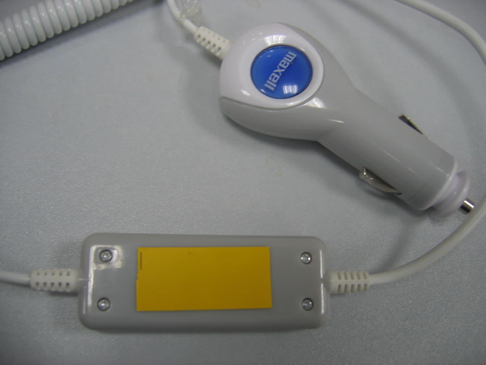
S4CKC9522
Mar 04, 2007FM Transmitter
Equipment Class
DXX - Part 15 Low Power Communication Device Transmitter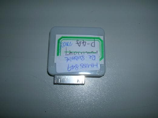
S4CKC9503
Feb 27, 2006FM Transmitter
Equipment Class
DXX - Part 15 Low Power Communication Device Transmitter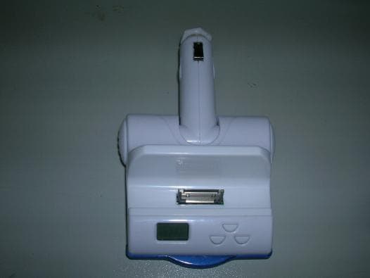
S4CKC9512
Feb 23, 2006FM Transmitter with Auto Power Adapter
Equipment Class
DXX - Part 15 Low Power Communication Device Transmitter