S52P1900-1iCell CDMA 1X BTS Module -1900 MHz
Star Solutions International Inc.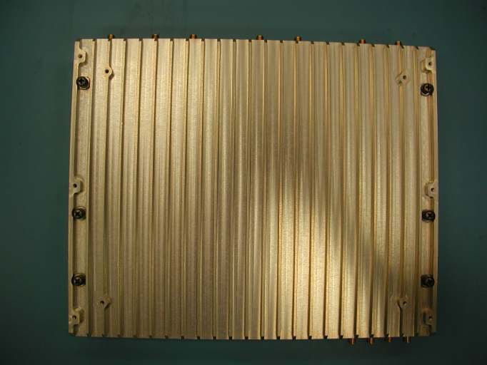
Click to zoom
Application Details
- Equipment Class
- PCB - PCS Licensed Transmitter
- Date of Grant
- Nov 08, 2005
- Application Purpose
- Original Equipment
- Date of Application
- Nov 08, 2005
- Equipment Note
- iCell CDMA 1X BTS Module -1900 MHz
- Frequency Range
- 1931.25000000 - 1988.75000000
- Country
- Canada
Documents & Files
Document Text
Text extracted from the exhibit documents filed with the FCC. Open a document above to read the original.
Users Manual
MovingMedia 2000 iCell Pico BTS Installation Guide Page 1 of 16 MovingMedia ® 2000 . iCell CDMA2000 1X Pico BTS BASIC INSTALLATION GUIDE RELEASE 4.5 DRAFT 0.1 PART NUMBER NXX0306XXX MovingMedia 2000 iCell Pico BTS Installation Guide Page 2 of 16 Copyright © 2005 UTStarcom Incorporated. All rights reserved. Copyright © 2005, UTStarcom, Inc. All rights reserved. No part of this documentation may be reproduced in any form or by any means or used to make any derivative work (such as translation, transformation, or adaptation) without prior written permission from UTStarcom, Inc. UTStarcom, Inc. reserves the right to revise this documentation and to make changes in content from time to time without obligation on the part of UTStarcom, Inc. to provide notification of such revision or change. UTStarcom, Inc. provides this documentation without warranty of any kind, either implied or expressed, including, but not limited to, the implied warranties of merchantability and fitness for a particular purpose. UTStarcom may make improvements or changes in the product(s) and/or the program(s) described in this documentation at any time. UNITED STATES GOVERNMENT LEGENDS: If you are a United States government agency, then this documentation and the software described herein are provided to you subject to the following: United States Government Legend: All technical data and computer software is commercial in nature and developed solely at private expense. Software is delivered as Commercial Computer Software as defined in DFARS 252.227-7014 (June 1995) or as a commercial item as defined in FAR 2.101(a) and as such is provided with only such rights as are provided in UTStarcom's standard commercial license for the Software. Technical data is provided with limited rights only as provided in DFAR 252.227-7015 (November 1995) or FAR 52.227-14 (June 1987), whichever is applicable. You agree not to remove or deface any portion of any legend provided on any licensed program or documentation contained in, or delivered to you in conjunction with, this User Guide. UTStarcom, the UTStarcom logo and MovingMedia 2000 are registered trademarks of UTStarcom, Inc. and its subsidiaries. Other brand and product names may be registered trademarks or trademarks of their respective holders. Regulatory This device complies with Part 15 of the FCC Rules. Operation of this device is subject to the following two conditions: (1) this device may not cause harmful interference, and (2) this device must accept any interference received including interference that may cause undesired operation. Where appropriate, the use of the equipment is subject to the following conditions: CAUTION! Unauthorized modifications or changes not expressly approved by UTStarcom could void compliance with regulatory rules, and thereby your authority to use this equipment. WARNING (EMI) - United States FCC Information - This equipment has been tested and found to comply with the limits pursuant to Part 15 of the FCC Rules. These limits are designed to provide reasonable protection against harmful interference in an appropriate installation. This equipment generates, uses, and can radiate radio frequency energy and, if not installed and used in accordance with the instructions, may cause harmful interference to radio communication. However, there is no guarantee that interference will not occur in a particular installation. If this equipment does cause harmful interference to radio or television reception, which can be determined by turning the equipment OFF and ON, the user is encouraged to try to correct the interference by one or more of the following measures: – Reorient or relocate the receiving antenna. – Increase the separation between the equipment and receiver. – Connect the equipment into an outlet on a circuit different from that to which the receiver is connected. – Consult the dealer or an experienced radio/TV technician To comply with Maximum Permissible Exposure (MPE) requirements, the maximum composite output from the antenna cannot exceed 1.26Watts EIRP and the antenna must be permanently installed in a fixed location that provides at least 20cm of separation from all persons. MovingMedia 2000 iCell Pico BTS Installation Guide Page 3 of 16 1 PREFACE 1.1 Objective This document provides installation and configuration instructions for setting up an iCell- CDMA2000 1X system. It covers physical installation, software installation for the various iCell components (sBSC and BTS), configuration, and initial system operation. 1.2 Organization The major sections of this guide are as follows: Table 1-1: Organization Table Chapter Title Description Chapter 1 Preface Introduction to the Installation Guide. Chapter 2 iCell System Description Describes the System components Chapter 3 BTS Physical Installation Provides mechanical installation and wiring instructions. MovingMedia 2000 iCell Pico BTS Installation Guide Page 4 of 16 1.3 Reference Documents The following table summarizes the applicable reference documents. Table 1-2: Reference Documents Ref. Title Number 1 iCell CDMA2000 1X Alarms and Statistics 2 iCell CDMA2000 1X Configuration Guide 1.4 Acronyms and Abbreviations The following table summarizes the acronyms and abbreviations used throughout the document. Table 1 -3: Acronyms and Abbreviations 1PPS One Pulse Per Second AAA Authentication, Authorization, and Accounting function Abis Protocol interface between sBSC and BTS ASN.1 The language used to define the MIB of the NE EM Element Manager GPS Global Positioning System HLR Home Location Register sBSC iCell Base Station Controller BTS iCell Base Station Transceiver Subsystem iMB iCell Main Board IOS Inter-Operability Standard; A-Interface between sBSC and MSC IP Internet Protocol iPA iCell Power Amplifier MIB Management Information Base MS Mobile Station (phone) MSC Mobile Switching Center NE Network Element or agent NOC Network Operations Center OID Object Identifier OMC Operations & Mainte…
Text truncated - open the document above for the full version.
Block Diagram
PCS BTS Block Diagram IFPC Front Interface PC Board IRPC Rear Interface PC board PCS BTS Core GPS Module 48051-61 From Trimble DC-DC converter 1 CPD250-4530 From PowerOne DC-DC converter 2 CPD250-4530 From PowerOne Power Interface Board GPS Backplane Board Fan Fan Fan -48V DC input
Cover Letter(s)
UTStarcom Canada 4600 Jacombs Road Richmond, B.C. Canada V6V 3B1 Main : 604.276.0055 Fax : 604.276.0501 www.utstar.com August 3, 2005 Intertek Testing Services NA, Inc. 1365 Adams Court, Menlo Park, CA USA 94025 Dear Sir or Madam: RE: Application for Confidentiality pursuant to CFR47 Section 0.459 and 0.457 for certification of PCS PICO Transceiver, FCC ID: S52P1900-1 UTStarcom Canada Limited FRN0012744488 requests that all the Schematics, Detailed Circuit Description and Schematics, Parts Lists, Internal Photos and all copies of these documents submitted for FCC ID: S52P1900-1 remain confidential due to the proprietary commercial information disclosed therein. These documents detail the exact nature of how our product is designed and would rapidly enable a competitor, without significant capital investment, to replicate our product. Confidentiality for internal photos has been requested since the BTS unit is not sold to the general public and the internal photos would reveal significant design ideas to competitors. The units are sold to licensed wireless operators as sealed units that are professionally installed in various enclosures. Please direct any questions or comments regarding this request to the undersigned. Regards, Richard LaLau, P.Eng. Director, Base Station Development UTStarcom Canada Limited 604.303.2331
Cover Letter(s)
UTStarcom Canada 4600 Jacombs Road Richmond, B.C. Canada V6V 3B1 Main : 604.276.0055 Fax : 604.276.0501 www.utstar.com August 3, 2005 Intertek Testing Services NA, Inc. 1365 Adams Court, Menlo Park, CA USA 94025 Dear Sir or Madam: RE: Authorization of Intertek Testing Services to obtain grant for S52P1900-1. UTStarcom Canada Ltd. hereby authorizes Intertek Testing Services NA, Inc., 1365 Adams Court, Menlo Park, CA USA 94025 (650-463-2900) to act on our behalf in all matters relating to applications for equipment authorization, including the signing of all documents relating to these matters for proposed FCCID: S52P1900-1. We further certify that no party to the applications authorization hereunder is subject to denial of benefits, that includes FCC benefits, pursuant to Section 5301 of the Anti-Drug Abuse Act of 1988, 21 U.S.C. 853 (a). Please direct any questions or comments regarding this request to the undersigned. This agreement expires one year from the above date. Regards, Richard LaLau, P.Eng. Director, Base Station Development UTStarcom Canada Ltd. 604.303.2331
Cover Letter(s)
UTStarcom Canada 4600 Jacombs Road Richmond, B.C. Canada V6V 3B1 Main : 604.276.0055 Fax : 604.276.0501 www.utstar.com August 3, 2005 Intertek Testing Services NA, Inc. 1365 Adams Court, Menlo Park, CA USA 94025 Re: Request for Limited Modular approval of Transceiver FCC ID: S52P1900-1 We request that the iCell Pico BTS Shelf transceiver module be approved as a modular unit, and the unit has the following features which meet the FCC requirement as outlined in its public notice PN27 Aug02. The unit meets the standalone requirements of a module per the following: (1) The unit has its own RF shielding such that the module does not have to rely upon the shielding provided by the device into which it is installed. (2) It has buffered data inputs - Ethernet RJ45 input. (3) The module has its own power supply regulation. (4) Antenna – The module is not sold with antenna. See note below. (5) The module is to be tested in a stand-alone configuration. The only connections required are: DC power, Ethernet RJ45 for control. The antenna is not normally sold with the unit. (6) The nodule will be labeled with its own FCC ID number, and, if the FCC ID is not visible when the module is installed inside another device, then the outside of the device into which the module is installed will display "Contains FCC ID:S52P1900-1” It will operate in Band Class 1, licensed 1900MHz PCS Band. Furthermore, UTSI has no plans to sell the module to an OEM. In other words, UTSI will control the mounting and installation of the module into either a plastic enclosure for wall mounting or into a metal chassis for rack mounting. UTSI will control the installation process such that compliance of the end product is assured. UTStarcom Inc. www.utstar.com The unit is not normally sold with antennas. Licensed 1900MHz PCS band operators will be responsible for selection of active or passive antennas and ensuring proper installation in commercial buildings. Sincerely, Richard LaLau, P.Eng. Director, Base Station Development UTStarcom Canada 604.303.2331
Cover Letter(s)
From: David Chernomordik ES-Mpk Sent: Tuesday, November 01, 2005 8:40 PM To: Roland Gubisch ES-Box Subject: FW: TCB certification application UTStarcom FCC ID: S52P1900-1 Hello Roland, Here is the respond to the first two items, provided by the Applicant: 1. DC voltage and current to the final RF transmit stage is 4.5V/450mA. 2. Each sector can transmit a single CDMA "carrier" at up to 100mW. Regarding the item 3: a) conducted output power was measured by using the spectrum analyzer build-in CDMA facility, which provides an average power measurement - channel power in 1.288 MHz bandwidth. b) antenna conducted out-of-band and spurious emissions were measured with average detector - sampling averaging c) Spurious radiated emissions were measured with resolution bandwidth of 30 kHz, video bandwidth of 300 Hz. A Bandwidth Correction Factor of 10Log(1250/30)=16 dB was added to the spectrum analyzer reading. This is equivalent of average radiated power measurement. Thanks David > -----Original Message----- > From: Roland Gubisch ES-Box > Sent: Tuesday, October 25, 2005 1:00 PM > To: David Chernomordik ES-Mpk > Cc: Terre Wolak ES-Atl > Subject: TCB certification application UTStarcom FCC ID: S52P1900-1 > > David, > > Technical review of this application is complete and the following points are noted: > > ADMINISTRATIVE > 1) 2.1033(c)(8) DC voltage and current into final RF stage cannot be found; please indicate where located, or provide. > > TECHNICAL > 1) This device has 3 sector outputs. Is the 100 mW output per sector? Does this transmitter support more than one carrier per output? > 2) Is the detector type used for output power the same as for spurious emissions? What is the detector type? > > Certification can proceed as soon as these issues are addressed. > > Thank you, > Roland >
External Photos
FCC ID: S52P1900-1 FCC ID: S52P1900-1 FCC ID: S52P1900-1 FCC ID: S52P1900-1 FCC ID: S52P1900-1
ID Label/Location Info
© 2005 UTStarcom Inc. Proprietary - 1 - Label Information FCC ID: S52P1900-1 © 2005 UTStarcom Inc. Proprietary - 2 - In addition, the Label to be used on the outside of enclosures or rack mount chassis would make reference to: “Contains FCC ID” as required for Modular Transceiver. Following is an example of this label: Model No. ____________ Serial No. ____________ FCC ID: S52P1900-1 Label location Model No. ____________ Serial No. ____________ Contains FCC ID: S52P1900-1 Model No. ____________ Serial No. ____________ FCC ID: S52P800-1
Parts List/Tune Up Info
© 2005 UTStarcom Inc. Proprietary and Confidential - 1 - FCC ID: S52P1900-1 iCell BTS 1900MHz Tune-up Procedure Draft Rev. 0.2 Date: August 3, 2005 © 2005 UTStarcom Inc. Proprietary and Confidential - 2 - RF Modem Description & Tune Up Procedure Transmit: CDMA Forward signal is developed in the Qualcomm CSM5000 CDMA modems in the main digital board of the BTS module. The digitizer module converts the signal to analog. This signal is up-converted to the desired channel frequency, amplified and filtered. The output power level is fixed at 100mW (+20dBm) for a typical CDMA physical and logic channel combination including pilot, synchronization, paging, and six arbitrary traffic channels. Output power is calibrated at the factory using calibrated power measurement equipment to ensure the target power is reached. Protection circuitry ensures the maximum desired output power is not exceeded. There are no field tunable components in the BTS module.
RF Exposure Info
RF Exposure evaluation (FCC 2.1091, 24.52) The EUT is a wireless device used in a mobile application, at least 20 cm from any body part of the user or nearby persons. Considering the maximum allowed antenna gain of 16.9 dBi (see report sec. 3.2), the maximum EIRP is 36.9 dBm or 4.9 W. Using the formula for the Power Density S = EIRP/ 4πD 2 , the distance D, where the Maximum Permissible Exposure (MPE) satisfies the FCC 1.1310 limit for General Population/Uncontrolled Exposure, can be calculated as: The MPE Limit at 1960 MHz is 1.0 mW/cm 2 (or 10 W/m 2 ), therefore, D > 0.197 m The Statement that a minimum separation distance of 20 cm between the antenna and persons must be maintained is included in the User’s manual.
Test Report
EMC Report for UTStarcom on the model: iCell 1900 MHz BTS Pico File: 3082574MPK-002 Page 1 of 43 Test Report Report Number: 3082574MPK-002 Project Number: 3082574 Report Date: September 12, 2005 Testing performed on the iCell CDMA 1X BTS Module - 1900 MHz Model Number: iCell 1900 MHz BTS Pico FCC ID: S52P1900-1 to FCC Part 24 for UTStarcom Canada Ltd. A2LA Certificate Number: 1755-01 Test Performed by: Test Authorized by: Intertek Testing Services NA, Inc 1365 Adams Court Menlo Park, CA 94025 4600 Jacombs Road Richmond, BC V6V3B1, Canada Prepared by: Date: September 15, 2005 David Chernomordik, EMC Technical Manager Reviewed by: Date: September 15, 2005 Ollie Moyrong, EMC Department Manager This report is for the exclusive use of Intertek's Client and is provided pursuant to the agreement between Intertek and its Client. Intertek's responsibility and liability are limited to the terms and conditions of the agreement. Intertek assumes no liability to any party, other than to the Client in accordance with the agreement, for any loss, expense or damage occasioned by the use of this report. Only the Client is authorized to copy or distribute this report and then only in its entirety. Any use of the Intertek name or one of its marks for the sale or advertisement of the tested material, product or service must first be approved in writing by Intertek. The observations and test results in this report are relevant only to the sample tested. This report by itself does not imply that the material, product, or service is or has ever been under an Intertek certification program. This report must not be used to claim product endorsement by A2LA, NIST nor any other agency of the U.S. Government. EMC Report for UTStarcom on the model: iCell 1900 MHz BTS Pico File: 3082574MPK-002 Page 2 of 43 TABLE OF CONTENTS 1.0 Introduction ...................................................................................................................4 1.1 Product Description..........................................................................................................4 1.2 Summary of Test Results..................................................................................................5 1.3 Test Configuration............................................................................................................6 1.3.1 Support Equipment....................................................................................6 1.3.2 Block diagram of Test Setup.....................................................................6 1.4 Related Submittal(s) Grants..............................................................................................6 2.0 RF Power Output ............................................................................................................7 2.1 Test Procedure..................................................................................................................7 2.2 Test Equipment.................................................................................................................7 2.3 Test Results ......................................................................................................................7 3.0 Radiated Power .............................................................................................................11 3.1 Requirement ...................................................................................................................11 3.2 Test Procedure................................................................................................................11 3.3 Test Results ....................................................................................................................11 4.0 Occupied Bandwidth.......................................................................................................12 4.1 Test Procedure................................................................................................................12 4.2 Test Equipment...............................................................................................................12 4.3 Test Results ....................................................................................................................12 5.0 Out of Band Emissions at Antenna Terminals.............................................................16 5.1 Requirement ...................................................................................................................16 5.2 Test Procedure................................................................................................................16 5.3 Test Equipment...............................................................................................................16 5.4 Test Results ....................................................................................................................16 6.0 Transmitter Spurious Radiation..................................................................................30 6.1 Requirement ...................................................................................................................30 6.2 Test Procedure................................................................................................................30 6.3 Test Equipment...............................................................................................................30 6.4 Configuration Photographs.............................................................................................31 6.5 Test Results ....................................................................................................................32 7.0 Receiver Radiated emissions ........................................................................................33 7.1 Radiated Emission Limits...............................................................................................33 7.2 Field Strength Calculation..........…
Text truncated - open the document above for the full version.
Contact Information
Applicant
Rundeep Chatha(Engineering Manager)
Technical Contact
Intertek Testing ServicesDavid Chernomordik
[email protected]650-463-2900
1365 Adams Court · Menlo Park, California · United States
Test Firm
Intertek Testing Services NA Inc.John Quigley
Technical Specifications
| # | Rule Parts | Frequency Range | Power Output | Emission | Tolerance |
|---|---|---|---|---|---|
| 1 | 24E | 1.93 GHz - 1.99 GHz | 100.00 mW | 1M25F9W | 100.0000000000 Hz |
Other Applications from Star Solutions International Inc.

S52-7-12-12-00-1
Oct 04, 2023LTE Base Station Band Class 12
Equipment Class
TNB - Licensed Non-Broadcast Station Transmitter
S52-1-10-01-00-1
Nov 20, 2013iCell QUADPAC IX IP-RAN 1900MHz CPU (wo CPU) AC GPS
Equipment Class
PCB - PCS Licensed Transmitter
S52-2-09-01-00-1
Jul 02, 2012iCell COMPAC DO IP-RAN 1900MHz CPU (/wo CPU) DC
Equipment Class
PCB - PCS Licensed Transmitter
S52-1-09-00-00-1
Jun 17, 2012iCell COMPAC 1X IP-RAN 800MHz CPU (/w0 CPU) DC
Equipment Class
TNB - Licensed Non-Broadcast Station Transmitter
S52-2-07-01-00-1
Nov 09, 2010Star Solutions iCell EVDO Indoor Compact BTS 1900MHz
Equipment Class
PCB - PCS Licensed Transmitter